Table of Contents
Advertisement
Quick Links
English
Configuration instructions
Universal encoder system – Generation II
Read the operating and assembly manual before carrying out assembly, starting
installation, or completing other work.
Store the manual for future use.
Translation of the original configuration instructions
ID 76633
®
U-ONE
-SAFETY-LWL
Edition: 01 2021
Advertisement
Table of Contents

Subscribe to Our Youtube Channel
Related Manuals for Hubner U-ONE-SAFETY-LWL Generation II


Summary of Contents for Hubner U-ONE-SAFETY-LWL Generation II
- Page 1 English Configuration instructions ® U-ONE -SAFETY-LWL Universal encoder system – Generation II Read the operating and assembly manual before carrying out assembly, starting installation, or completing other work. Store the manual for future use. Translation of the original configuration instructions Edition: 01 2021 ID 76633...
- Page 2 ® U-ONE -SAFETY-LWL Configuration manual Manufacturer / Publisher Johannes Hübner Phone: +49 641 7969 0 Fabrik elektrischer Maschinen GmbH Fax: +49 641 73645 Siemensstr. 7 Internet: www.huebner-giessen.com 35394 Giessen / Germany E-Mail: info@huebner-giessen.com Further current information on this product series can be found online in our Service Point.
- Page 3 ® U-ONE -SAFETY-LWL Configuration manual Trademarks Brand names and product names are trademarks or registered trademarks of their respective owner. Protected trademarks bearing a ™ or ® symbol are not always depicted as such in the manual. However, the statutory rights of the respective owners remain unaffected. Copyright It is strictly forbidden to reproduce this publication or parts of this publication in any form or by any means without the prior written permission of Johannes Hübner Fabrik elektrischer Maschinen...
-
Page 4: Table Of Contents
® U-ONE -SAFETY-LWL Configuration manual Table of contents 1 System description ......................6 1.1 Explanation of symbols ....................6 1.2 System structure and function ..................7 2 Software ........................... 8 2.1 Software installation ....................8 2.1.1 Manual driver installation ..................8 2.2 General description of the software ................ - Page 5 ® U-ONE -SAFETY-LWL Configuration manual 5.1.2 Speed-dependent current output ............... 25 5.2 Incremental output ....................26 5.3 PROFIBUS-DP interface (UO-EPB-1) ..............26 6 Additional functions ...................... 27 6.1 Reset ........................27 6.2 Transmit system data to other systems ..............27 6.3 Create system data set without U-ONE-SAFETY-fibre optic ........
-
Page 6: System Description
® U-ONE -SAFETY-LWL Configuration manual 1 System description ® In this document, the U-ONE -SAFETY-LWL system is referred to as the USL, and the USL function module is referred to as the “module”. This manual describes how to configure the module using the US42Pro software and transfer configurations to the device. -
Page 7: System Structure And Function
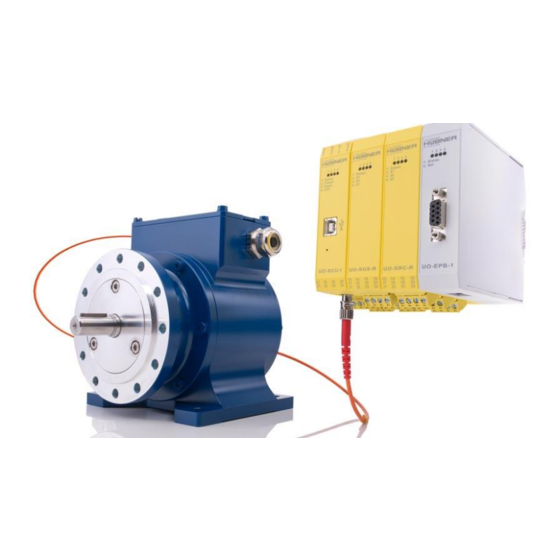
® U-ONE -SAFETY-LWL Configuration manual 1.2 System structure and function The USL consists of a basic device, a section of fibre optic cable, a UO-SCU module, and other optional modules. The SCU is the central control module for the USL. All function modules and the basic device are registered and managed in the UO-SCU. -
Page 8: Software
® U-ONE -SAFETY-LWL Configuration manual 2 Software 2.1 Software installation System requirements: ® Commonly available Windows laptops/PCs with the following system requirements are used as configuration computers: Windows ® 7 / 8 / 8.1 / 10. 64-bit operating system ... -
Page 9: General Description Of The Software
® U-ONE -SAFETY-LWL Configuration manual Fig. 2-2: Driver installation Now, as the installation source, select the path for your installation by clicking “Search”. There, select the drivers folder. Click “Continue” to start the installation. Click “Continue” to complete installation of the driver software for the USL. End the installation by clicking “Close”. The USL can now be used. - Page 10 ® U-ONE -SAFETY-LWL Configuration manual authentication. The password must be between 6 and 12 ASCII characters (0x20 - 0x7E) long. Level 0: Observer (no password) The following functions are available: Establishing communication with the modules Entering a password ...
-
Page 11: Help
® U-ONE -SAFETY-LWL Configuration manual 2.2.3 Help Pull-down menu “?” Information The software version and contact information for the Johannes Hübner company are displayed here. A support file can be generated. Help This option opens the available configuration manual in PDF format. Documentation This option opens the folder with USL 42 documentation. -
Page 12: Save Configuration Data
® U-ONE -SAFETY-LWL Configuration manual 2.2.4 Save configuration data A formal review of all entries will be completed before data transmission. Incorrect entries will be highlighted in red, and transmission will be stopped. If entries are correct according to the rules (sec. 3.5.2.1), then the values are transmitted to the module, checked, activated, and saved temporarily. -
Page 13: Basic System Configuration
® U-ONE -SAFETY-LWL Configuration manual 3 Basic system configuration Required modules USL(H) 42 Basic Device UO-SCU Module Please see the specific module operating and assembly manuals for further important information. Take sufficient time to plan your work and to configure the module. Please note that errors in planning and configuration could endanger personnel. -
Page 14: Start The Us42Pro Software
® U-ONE -SAFETY-LWL Configuration manual 3.3 Start the US42Pro software The home screen will appear after you start the software. Click “Connect” to establish communication with the USL. The display to the right of the button indicates the connection status. Display Status grey... -
Page 15: Calibrating The Position System
® U-ONE -SAFETY-LWL Configuration manual 3.5 Calibrating the position system The position system is calibrated (adjusting the internal group processing to the reality at the installation location) using “Edit calibration settings” The calibration settings are displayed and edited here. Settings can be changed using “Start configuration”. -
Page 16: Determining The Preset Position
® U-ONE -SAFETY-LWL Configuration manual Determining the calibration factor through calculation Calibration factor = (rotations of the device shaft) x 8192 / real distance in system units. Example: 34.5 m travel distance, corresponding to 125.7 rotations of the device shaft. Calibration factor = 125.7 x 8192 / 34.5 = 29847.37 3.5.3 Determining the preset position The preset position is a defined position point (calibration point). -
Page 17: Configuring Safety-Related Functions
® U-ONE -SAFETY-LWL Configuration manual 4 Configuring safety-related functions 4.1 Position switch (UO-SRC-R) Required modules USL(H) 42 Basic Device UO-SCU Module UO-SCR-R module Please see the specific module operating and assembly manuals for further important information. The UO-SRC-R is a safe position switch module, and contains 3 position switches. The position switches open and close depending on the position value. -
Page 18: Illustration In The Display Area
® U-ONE -SAFETY-LWL Configuration manual NOTE! If the switching points are configured so that the minimum switching distance Tmin (= 2ms) between two switching state changes may not be met at the max. permitted speed, then relay switching is not ensured, and the fields are marked (warning). In such cases, the user must check the circumstances for their application and ensure that Tmin is always met. -
Page 19: Preset
® U-ONE -SAFETY-LWL Configuration manual 4.2 Preset Required modules USL(H) 42 Basic Device UO-SCU Module Please see the specific module operating and assembly manuals for further important information. A preset will set the current position of the preset position which can be configured in the UO-SCU. -
Page 20: Speed Switch (Uo-Sgs-R)
® U-ONE -SAFETY-LWL Configuration manual 4.3 Speed switch (UO-SGS-R) Required modules USL(H) 42 Basic Device UO-SCU Module UO-SGS-R module Please see the specific module operating and assembly manuals for further important information. The UO-SGS-R is a safe speed switching module. The speed switch opens and closes depending on the speed. -
Page 21: Low Speed
® U-ONE -SAFETY-LWL Configuration manual Note The following conditions apply to the speed switching points: P1 <= 0.9 x P2; P2 <= 0.9 x P3; P3 <= 0.9 x P4 or P1 = P2 = 0 Entering “0” in the fields P1 ... P4 deactivates the relevant switch. Entering “0”... -
Page 22: Input Precision For Switching Points
® U-ONE -SAFETY-LWL Configuration manual 4.3.5 Input precision for switching points The input precision for speed switching points will depend on the speed range, and is limited to 4 decimal places. The entry is limited to 2 positions after the decimal point. Switching speed n Input precision X: Positions before the... -
Page 23: Safe Error Switch
® U-ONE -SAFETY-LWL Configuration manual 4.5 Safe error switch Required modules USL(H) 42 Basic Device UO-SCU Module UO-SRC-R or UO-SGS-R module Please see the specific module operating and assembly manuals for further important information. The error state can be assigned to a switching output (relay) using the configuration software. The safe error switch must be used so that the application enters a safe state when the switch is opened (see section 9). -
Page 24: Profinet Io Interface And Profisafe Profile (Uo-Spn-1)
® U-ONE -SAFETY-LWL Configuration manual NOTE! The UO-SPB-1 can only be configured via the field bus interface. A preset over the field bus interface does not influence the preset specified in the UO-SCU. We recommend setting both presets to the same value when the module is shut down. -
Page 25: Position-Dependent Current Output
® U-ONE -SAFETY-LWL Configuration manual 5.1.1 Position-dependent current output 2 position values within the working area limits must be entered to configure the position-dependent current output. The smaller position value is assigned to current I mA and the larger position value I = 20 mA. -
Page 26: Incremental Output
® U-ONE -SAFETY-LWL Configuration manual 5.2 Incremental output Required modules USL(H) 42 Basic Device UO-SCU-G Module Please see the specific module operating and assembly manuals for further important information. The incremental output is optional and is installed in the UO-SCU-G. -
Page 27: Additional Functions
® U-ONE -SAFETY-LWL Configuration manual 6 Additional functions 6.1 Reset A reset will reinitialise the entire USL, and will reset errors as well, depending on the configuration (see section 8). 6.2 Transmit system data to other systems System data can be transmitted to other USL systems of the same design. Data is saved using: Pull-down menu: File ... -
Page 28: Replacing Modules
® U-ONE -SAFETY-LWL Configuration manual 6.4 Replacing modules If the system configuration has been changed or modules have been replaced, this is detected and displayed when the USL is switched on. The system remains in an error state. The changed configuration can be released using the configuration software. -
Page 29: Firmware Update
® U-ONE -SAFETY-LWL Configuration manual 6.6 Firmware update Pull-down menu: Options Firmware update 6.6.1 Module firmware update The modules are prepared for a firmware update by pressing the button on the front plate of the UO-SCU during the switch on process. Press the button to select the update file. -
Page 30: Resetting A Password
® U-ONE -SAFETY-LWL Configuration manual 6.8 Resetting a password Pull-down menu: Options Reset password If you forget your password, you can use “Reset password” to assign a new password by completing the following steps: 1. Select the password level you would like to reset. -
Page 31: Safety Data Sheet
® U-ONE -SAFETY-LWL Configuration manual 7 Safety data sheet 7.1 Safety parameters Architecture Category SIL CL Service life 1oo2 20 years (2-channel) (high demand) The safety parameters for the U-ONE-SAFETY-LWL are based on the safety parameters of the modules required for the safety function. 7.1.1 Examples Safe speed switch: The components basic device USL(H)42, the UO-SCU module and the UO-SGS-R module are... -
Page 32: Timing
® U-ONE -SAFETY-LWL Configuration manual 7.2 Timing Power on time Internal diagnostic measures are carried out first after the supply voltage is switched on, before the USL is ready for operation. Function Time ≤ 4 s Power on time 7.3 Safe state ... -
Page 33: Troubleshooting
® U-ONE -SAFETY-LWL Configuration manual Relays that do not change their switching state for longer than 1 year due to the application must be inspected once annually as part of maintenance work. 8 Troubleshooting While the USL is being switched on and while it is running, a wide range of diagnostic measures check the function and operating conditions of the overall USL. -
Page 34: Error Memory
® U-ONE -SAFETY-LWL Configuration manual 8.1 Error memory Time: Time at which the error occurred (operating hours) Source: module causing the error Error number: Storage location for the error The error memory is a ring buffer and can record 100 error entries. Internal errors should be sent to the manufacturer for analysis. -
Page 35: Check List
® U-ONE -SAFETY-LWL Configuration manual Error no. Description 80, 84 Basic device not found Basic device was exchanged Basic device firmware not compatible 86, 87 Module removed, exchanged Firmware in module not compatible Max. number of modules exceeded 100 - 255 Internal diagnostic error detected 8.3 Check list We recommend printing out the check list and working through it during commissioning, when replacing the measurement system and when changing the parameters for systems that have... -
Page 36: Example Applications
® U-ONE -SAFETY-LWL Configuration manual 9 Example applications The USL provides a safe position / speed switch. The switches are shown powered down. Non safety-related data lines and switches are shown in black. Use with SAFETY PLC Safety-related SPS This illustration shows the USL as a safe sub- system for the safety-related PLC.
Need help?
Do you have a question about the U-ONE-SAFETY-LWL Generation II and is the answer not in the manual?
Questions and answers