Table of Contents
Advertisement
Quick Links
English
Operating and Assembly Instructions
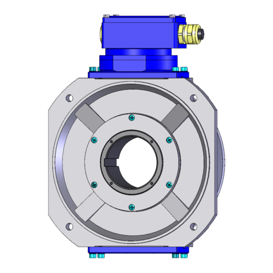
Incremental hollow shaft encoder FGH 8
Read the operating and assembly instructions prior to
assembly, starting installation and handling!
Keep for future reference!
Translation of the original Operating and Assembly Instructions
FGH8_MANUAL-en_R6(2018-11-19)ID74584.docx
ID 74584
Advertisement
Table of Contents

Subscribe to Our Youtube Channel
Related Manuals for Hubner FGH 8


Summary of Contents for Hubner FGH 8
- Page 1 English Operating and Assembly Instructions Incremental hollow shaft encoder FGH 8 Read the operating and assembly instructions prior to assembly, starting installation and handling! Keep for future reference! Translation of the original Operating and Assembly Instructions FGH8_MANUAL-en_R6(2018-11-19)ID74584.docx ID 74584...
- Page 2 Johannes Hubner Fabrik elektrischer Maschinen GmbH. Subject to errors and changes due to technical improvements. Copyright © Johannes Hubner Fabrik elektrischer Maschinen GmbH All rights reserved. FGH8_MANUAL-en_R6(2018-11-19)ID74584.docx...
-
Page 3: Table Of Contents
Incremental hollow shaft encoder FGH 8 Directory 1 General ..........................5 1.1 Information about the Operating and Assembly Instructions ........5 1.2 Scope of delivery ....................... 5 1.3 Explanation of symbols ....................5 1.4 Disclaimer ........................6 1.5 Copyright ........................6 1.6 Guarantee terms ...................... - Page 4 Incremental hollow shaft encoder FGH 8 8 Inspections ........................19 8.1 Safety instructions .....................19 8.2 Maintenance information ...................19 8.3 Inspection schedule ....................19 9 Disposal ..........................20 9.1 Disposal procedure ....................20 10 Dimension drawings ......................21 11 Connections ........................28 FGH8_MANUAL-en_R6(2018-11-19)ID74584.docx...
-
Page 5: General
In addition, applicable local regulations for the prevention of industrial accidents and general safety regulations must be complied with. 1.2 Scope of delivery Incremental hollow shaft encoder FGH 8, Operating and Assembly Instructions. 1.3 Explanation of symbols Warnings are indicated by symbols in these operating and assembly instructions. The warnings are introduced by signal words that express the scope of the hazard. -
Page 6: Disclaimer
2.2 Intended use The device has been designed and constructed exclusively for the intended use described here. Series FGH 8 Incremental hollow shaft encoder are used for measurement of rotations, for instance of electrical and mechanical drives and shafts. Claims of any type due to damage arising from non-intended use are excluded; the owner bears sole responsibility for non-intended use. -
Page 7: Improper Use
Incremental hollow shaft encoder FGH 8 2.3 Improper use Do not use the device in potentially explosive areas. The device must not be subjected to mechanical loads in addition to its own weight and unavoidable vibration and shock loads that arise during normal operations. -
Page 8: Special Dangers
Incremental hollow shaft encoder FGH 8 2.6 Special dangers Residual risks that have been determined based on a risk assessment are cited below. 2.6.1 Electrical current DANGER! Life-threatening danger due to electrical shock! There is an imminent life-threatening hazard if live parts are touched. Damage to insulation or to specific components can pose a life-threatening hazard. -
Page 9: Technical Data
Incremental hollow shaft encoder FGH 8 3 Technical Data 3.1 Type plate The figure below shows an example of a nameplate: Encoder with 2 terminal boxes The type plate is located on the outside of the housing and contains the following information: ... - Page 10 Incremental hollow shaft encoder FGH 8 Pulse duty factor 1 : 1 ± 5 % to 50 kHz < 3 % Square wave displacement 0°, 90° to 150 kHz < 5 % Max. frequency 0 to 100 kHz (150 kHz on request)
- Page 11 Incremental hollow shaft encoder FGH 8 Signal outputs Basic version (n = pulses/revolution) One pulse channel (basic) with n direct square wave pulses, corresponding to the segment division and LED monitoring output. (optional). Option 90 pulse channel as basic version, but with 90°...
-
Page 12: Type Code
Incremental hollow shaft encoder FGH 8 3.3 Type code 1000 G 90G Incremental hollow shaft encoder Encoder with insulating sleeve Series Connection method 2x connection = redundant encoder z.B. EEK: 2x terminal box EK/EEK: terminal box ES/EES: EMC industrial plug ER/EER: 12-pole. -
Page 13: Transport, Packaging And Storage
Incremental hollow shaft encoder FGH 8 4 Transport, packaging and storage 4.1 Safety instructions for transport CAUTION! Material damage caused by improper transport! Observe the symbols and information on the packaging: Do not throw - risk of breakage ... -
Page 14: Installation And Commissioning
Incremental hollow shaft encoder FGH 8 5 Installation and commissioning 5.1 Safety instructions Personnel Installation and commissioning must be carried out by skilled technical staff only. NOTES! Observe the safety instructions contained in Chapter 2 when installing or working on the device! 5.2 Mounting of the encoder (mechanical) - Page 15 Incremental hollow shaft encoder FGH 8 Mounting / removal sleeves for standard bores FGH 8.. Drg. no. E-52 443a FGH 8 / B 14 Drg. no. E-52 760 Only mounting sleeve NOTES! The radial deviation of the shaft ( Fig. 2) should not exceed 0,05 mm.
-
Page 16: Connecting The Encoder
Incremental hollow shaft encoder FGH 8 5.3 Connecting the encoder 5.3.1 Connections Cable glands are closed with a stopper to protect the devices on transport and storage. Cable connections: Have to be executed according to the encoder type. Connection diagrams have to be considered! Use of connection cables with diameter of min. -
Page 17: Technical Note
Incremental hollow shaft encoder FGH 8 5.3.2 Technical note Ambient temperature The permissible ambient temperature depends on the speed and degree of protection (shaft seal) of the device and the frequency, the signal cable length and mounting situation. See chapter 3.2... -
Page 18: Faults
Signal end stage overloaded Check pin assignment; observe connection diagram Do not assign unused outputs Signal interruptions Outputs short-circuited Do not connect outputs with supply voltage or GND Contact Hubner-Service (page 2) if none of the remedies listed above provides a solution)! FGH8_MANUAL-en_R6(2018-11-19)ID74584.docx... -
Page 19: Inspections
Incremental hollow shaft encoder FGH 8 8 Inspections 8.1 Safety instructions Personnel Skilled technical staff only are permitted to inspect the device and its installation. Observe the safety instructions contained in Chapter 2 when inspecting or working on the device. -
Page 20: Disposal
Incremental hollow shaft encoder FGH 8 9 Disposal 9.1 Disposal procedure The manufacturer is not obliged to take back the device. The device is classed as electronic equipment and subject to the WEEE Directive; observe local, country-specific laws when disposing of the device. -
Page 21: Dimension Drawings
Incremental hollow shaft encoder FGH 8 10 Dimension drawings FGH8_MANUAL-en_R6(2018-11-19)ID74584.docx... - Page 22 Incremental hollow shaft encoder FGH 8 FGH8_MANUAL-en_R6(2018-11-19)ID74584.docx...
- Page 23 Incremental hollow shaft encoder FGH 8 FGH8_MANUAL-en_R6(2018-11-19)ID74584.docx...
- Page 24 Incremental hollow shaft encoder FGH 8 FGH8_MANUAL-en_R6(2018-11-19)ID74584.docx...
- Page 25 Incremental hollow shaft encoder FGH 8 FGH8_MANUAL-en_R6(2018-11-19)ID74584.docx...
- Page 26 Incremental hollow shaft encoder FGH 8 FGH8_MANUAL-en_R6(2018-11-19)ID74584.docx...
- Page 27 Incremental hollow shaft encoder FGH 8 FGH8_MANUAL-en_R6(2018-11-19)ID74584.docx...
-
Page 28: Connections
Incremental hollow shaft encoder FGH 8 11 Connections FGH 8 standard terminal box FGH 8 standard connection cable FGH8_MANUAL-en_R6(2018-11-19)ID74584.docx... - Page 29 Incremental hollow shaft encoder FGH 8 12 – pole round plug FGH 8 standard 15 – pole industrial plug FGH 8 standard FGH8_MANUAL-en_R6(2018-11-19)ID74584.docx...
- Page 30 Incremental hollow shaft encoder FGH 8 FGH 8 standard 42 pole industrial plug FGH8_MANUAL-en_R6(2018-11-19)ID74584.docx...
Need help?
Do you have a question about the FGH 8 and is the answer not in the manual?
Questions and answers