Table of Contents
Advertisement
Quick Links
English
Operating and Assembly Instructions
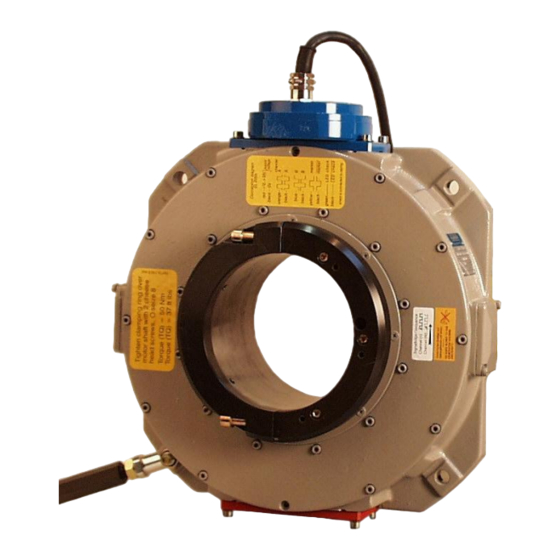
Incremental hollow shaft encoder FGH 14
Read the Operating and Assembly Instructions prior to
assembly, starting installation and handling!
Keep for future reference!
Translation of the original Operating and Assembly Instructions FGH14_MANUAL-en_R5(2017-08-14)ID68166.doc
ID 68166
Advertisement
Table of Contents

Subscribe to Our Youtube Channel
Related Manuals for Hubner FGH 14


Summary of Contents for Hubner FGH 14
- Page 1 English Operating and Assembly Instructions Incremental hollow shaft encoder FGH 14 Read the Operating and Assembly Instructions prior to assembly, starting installation and handling! Keep for future reference! Translation of the original Operating and Assembly Instructions FGH14_MANUAL-en_R5(2017-08-14)ID68166.doc ID 68166...
- Page 2 Johannes Hubner Fabrik elektrischer Maschinen GmbH. Subject to errors and changes due to technical improvements. Copyright © Johannes Hubner Fabrik elektrischer Maschinen GmbH All rights reserved. FGH14_MANUAL-en_R5(2017-08-14)ID68166.doc...
-
Page 3: Table Of Contents
Incremental hollow shaft encoder FGH 14 Directory 1 General ..........................5 1.1 Information about the Operating and Assembly Instructions ........5 1.2 Scope of delivery ....................... 5 1.3 Explanation of symbols ....................5 1.4 Disclaimer ........................6 1.5 Copyright ........................6 1.6 Guarantee terms ...................... - Page 4 Incremental hollow shaft encoder FGH 14 7.1 Faults table .......................18 8 Inspections ........................19 8.1 Safety instructions .....................19 8.2 Maintenance information ...................19 8.3 Inspection schedule ....................19 9 Incremental encoder with replaceable scanning head ..........20 9.1 Exchange of scanning-system ..................21 9.2 Pictures ........................22 10 Disposal ..........................23...
-
Page 5: General
In addition, applicable local regulations for the prevention of industrial accidents and general safety regulations must be complied with. 1.2 Scope of delivery Incremental hollow shaft encoder FGH 14, Operating and Assembly Instructions. 1.3 Explanation of symbols Warnings are indicated by symbols in these Operating and Assembly Instructions. The warnings are introduced by signal words that express the scope of the hazard. -
Page 6: Disclaimer
2.2 Intended use The device has been designed and constructed exclusively for the intended use described here. Series FGH 14 hollow shaft encoders are used for measurement of rotations, for instance of electrical and mechanical drives and shafts. Claims of any type due to damage arising from non-intended use are excluded; the owner bears sole responsibility for non-intended use. -
Page 7: Improper Use
Incremental hollow shaft encoder FGH 14 2.3 Improper use Do not use the device in potentially explosive areas. The device must not be subjected to mechanical loads in addition to its own weight and unavoidable vibration and shock loads that arise during normal operations. -
Page 8: Special Dangers
Incremental hollow shaft encoder FGH 14 2.6 Special dangers Residual risks that have been determined based on a risk assessment are cited below. 2.6.1 Electrical current DANGER! Life-threatening danger due to electrical shock! There is an imminent life-threatening hazard if live parts are touched. Damage to insulation or to specific components can pose a life-threatening hazard. -
Page 9: Technical Data
Incremental hollow shaft encoder FGH 14 3 Technical Data 3.1 Type plate Encoder FGH 14 EEK Encoder with 2 terminal boxes The type plate is located on the outside of the housing and contains the following information: Manufacturer, Address ... - Page 10 Incremental hollow shaft encoder FGH 14 Duty cycle 1 : 1 ± 5 % to 50 kHz < 3 % Square wave displacement 0°, 90° to 150 kHz < 5 % Max. frequency 0 to 100 kHz (150 kHz on request) Encoder temperature ranges 0°C …...
- Page 11 Incremental hollow shaft encoder FGH 14 Signalausgänge Basic version (n = pulses/revolution) One pulse channel (basic) with n direct square wave pulses, corresponding to the segment division and LED monitoring output. (optional). Option 90 pulse channel as basic version, but with 90°...
-
Page 12: Type Code
Incremental hollow shaft encoder FGH 14 3.3 Type code 14 EK 1000 /140 P Incremental encoder type 14 = FG …14 only for hollow shaft bore Ø 93...Ø 150 Drive shaft connection P: keyway K: clamp S: pressure sleeve C: taper... -
Page 13: Transport, Packaging And Storage
Incremental hollow shaft encoder FGH 14 4 Transport, packaging and storage 4.1 Safety instructions for transport CAUTION! Material damage caused by improper transport! Observe the symbols and information on the packaging: Do not throw - risk of breakage ... -
Page 14: Installation And Commissioning
Incremental hollow shaft encoder FGH 14 5 Installation and commissioning 5.1 Safety instructions Personnel Installation and commissioning must be carried out by skilled technical staff only. NOTES! Observe the safety instructions contained in Chapter 2 when installing or working on the device! 5.2 Mounting of the encoder (mechanical) - Page 15 Incremental hollow shaft encoder FGH 14 Mounting / removal sleeves for standard bores FGH 14… / 140P Drg. no. D-52 833a-I FGH 14… / 93 S and 150 K Drg. no. D-52 833a-II See separate assembly and disassembly instructions Nr.54728...
-
Page 16: Connecting The Encoder
Incremental hollow shaft encoder FGH 14 5.3 Connecting the encoder 5.3.1 Connections Cable glands are closed with a stopper to protect the devices on transport and storage. Cable connections: Have to be executed according to the encoder type. Connection diagrams have to be considered! See chapter 13 and in the terminal box cover. -
Page 17: Technical Information
Incremental hollow shaft encoder FGH 14 5.3.2 Technical information Ambient temperature The max. permissible ambient temperature depends on the speed and degree of protection of the device, the signal frequency, the length of the signal cable and the place of installation (please refer to Chapter3.2). -
Page 18: Faults
Signal end stage overloaded Check pin assignment; observe connection diagram Do not assign unused outputs Signal interruptions Outputs short-circuited Do not connect outputs with supply voltage or GND Contact Hubner-Service (page 2) if none of the remedies listed above provides a solution)! FGH14_MANUAL-en_R5(2017-08-14)ID68166.doc... -
Page 19: Inspections
Incremental hollow shaft encoder FGH 14 8 Inspections 8.1 Safety instructions WARNING! Skilled technical staff only are permitted to inspect the device and its installation. Observe the safety instructions contained in Chapter 2 when inspecting or working on the device! 8.2 Maintenance information... -
Page 20: Incremental Encoder With Replaceable Scanning Head
Incremental hollow shaft encoder FGH 14 9 Incremental encoder with replaceable scanning head Hollow shaft incremental encoder with bores from Ø 93 mm up to Ø 150 mm Suitable for harsh ambient conditions, such as in opencast mining, steel and rolling mills. -
Page 21: Exchange Of Scanning-System
Incremental hollow shaft encoder FGH 14 9.1 Exchange of scanning-system of Encoder FGH 14. Easy exchange of all optical and electronic components without removal of the encoder form motor shaft. 1. Remove scanning head SCANNING-SYSTEM area must be cleaned... -
Page 22: Pictures
Incremental hollow shaft encoder FGH 14 9.2 Pictures Photo No. 1 to 6: Sequence of disassembly / exchange = Scanning - System FGH14_MANUAL-en_R5(2017-08-14)ID68166.doc... -
Page 23: Disposal
Incremental hollow shaft encoder FGH 14 10 Disposal 10.1 Disposal procedure The manufacturer is not obliged to take back the device. The device is classed as electronic equipment and subject to the WEEE Directive; observe local, country-specific laws when disposing of the device. -
Page 24: Ec-Declaration Of Incorporation
Incremental hollow shaft encoder FGH 14 11 EC-Declaration of Incorporation FGH14_MANUAL-en_R5(2017-08-14)ID68166.doc... - Page 25 Incremental hollow shaft encoder FGH 14 FGH14_MANUAL-en_R5(2017-08-14)ID68166.doc...
- Page 26 Incremental hollow shaft encoder FGH 14 FGH14_MANUAL-en_R5(2017-08-14)ID68166.doc...
-
Page 27: Dimension Drawings
Incremental hollow shaft encoder FGH 14 12 Dimension drawings FGH 14 EK / EEK…140P HM 14 M 107307 FGH14_MANUAL-en_R5(2017-08-14)ID68166.doc... - Page 28 Incremental hollow shaft encoder FGH 14 FGH 14 EC… / 93 S Annex with torque bracket HM 12 M 105102 FGH14_MANUAL-en_R5(2017-08-14)ID68166.doc...
- Page 29 Incremental hollow shaft encoder FGH 14 FGH 14 EC… / 150 K mod Annex with torque bracket HM 12 M 105099 FGH14_MANUAL-en_R5(2017-08-14)ID68166.doc...
- Page 30 Incremental hollow shaft encoder FGH 14 FGH 14 EK / EEK / 108 C taper 1:10 HM 02 M 55 614 FGH14_MANUAL-en_R5(2017-08-14)ID68166.doc...
- Page 31 Incremental hollow shaft encoder FGH 14 FGH 14 EER / 148 C HM 14 M 107830 Further dimension drawings on our Website or on request. FGH14_MANUAL-en_R5(2017-08-14)ID68166.doc...
-
Page 32: Connections
Incremental hollow shaft encoder FGH 14 13 Connections FGH 14 Standard Terminal box FGH 14 Standard Connection cable FGH14_MANUAL-en_R5(2017-08-14)ID68166.doc... - Page 33 Incremental hollow shaft encoder FGH 14 12 – pole Burndy plug FGH 14 Standard 15 – pole Harting plug FGH 14 Standard FGH14_MANUAL-en_R5(2017-08-14)ID68166.doc...
- Page 34 Incremental hollow shaft encoder FGH 14 FGH 14 Standard 42 pole industry plug FGH14_MANUAL-en_R5(2017-08-14)ID68166.doc...
-
Page 35: Annex
Incremental hollow shaft encoder FGH 14 14 Annex Mounting and Removal Instruction 2010-01-04 of Incremental Hollow Shaft Encoder Encoder TYPE: FGH 14…/ .S Mounting Tool: with torque wrench Type: FGH 14… / .S Type: FGH 14… / 150 K TQ = 25 Nm or TQ = 50 Nm or bore: Ø... - Page 36 Incremental hollow shaft encoder FGH 14 FGH14_MANUAL-en_R5(2017-08-14)ID68166.doc...
- Page 37 Incremental hollow shaft encoder FGH 14 FGH14_MANUAL-en_R5(2017-08-14)ID68166.doc...
- Page 38 Incremental hollow shaft encoder FGH 14 FGH14_MANUAL-en_R5(2017-08-14)ID68166.doc...
- Page 39 Incremental hollow shaft encoder FGH 14 bore: 10 Nm (95) 7,5 ft lbs FGH14_MANUAL-en_R5(2017-08-14)ID68166.doc...
- Page 40 Incremental hollow shaft encoder FGH 14 FGH14_MANUAL-en_R5(2017-08-14)ID68166.doc...
Need help?
Do you have a question about the FGH 14 and is the answer not in the manual?
Questions and answers