Table of Contents
Advertisement
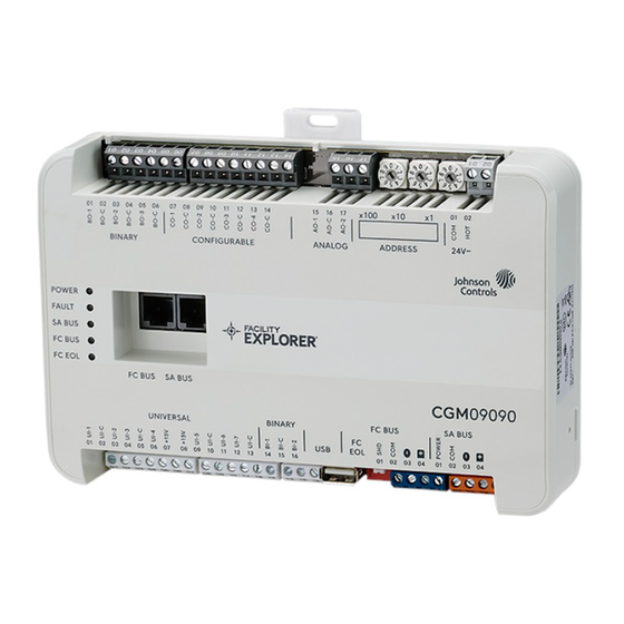
Application
The CG series general purpose application controllers
are well-suited for controlling a wide variety of facility
and HVAC equipment, including fan coils, air handling
units, packaged HVAC equipment, and central plant
equipment. CG series controllers run pre-engineered and
user-programmed applications.
CG series controllers include an integral real-time clock,
which enables the controllers to monitor and control
schedules, calendars, and trends, and operate for
extended periods of time as standalone controllers when
offline from the Facility Explorer system network. Certain
models feature an integral color display with a navigation
keypad that enables enhanced local monitoring and
control of field equipment.
Communications Protocols
CG series controllers can communicate using multiple
communication protocols depending on model and
configuration. CGE controllers communicate using the
BACnet
Secure Connect (BACnet/SC) or BACnet/IP
®
communication protocol. CGM controllers communicate
using the BACnet MS/TP, N2 or wireless communications
protocols, with the addition of ZFR183x Pro Wireless Field
Bus Routers.
Equipment controllers in BACnet/SC, BACnet/IP, or
BACnet MS/TP communication mode are BACnet network-
compliant devices. The BACnet protocol is a standard
for ANSI, ASHRAE, and the International Standards
Organization (ISO) for building controls.
Controllers running in N2 mode can be used to maintain
or modernize sites with installed legacy Johnson Controls
controllers. For installation and commissioning support,
and tips for efficient and safe replacement, refer
to the Modernization Guide for Legacy N2 Controllers
(LIT-12012005) and the controller-specific documentation.
For information about mapping N2 Objects in controllers
with switchable communications protocols, refer to the
N2 Compatibility Options chapter of the Controller Tool Help
(LIT-12011147). To configure CGM series controllers to
communicate using the N2 communications protocol, see
Configuring N2 communications (CGM models
To configure CGM controllers to communicate using
the wireless communications protocol, see
wireless communications (CGM models
F4-CG Series General Purpose Application
Controllers Installation Guide
North American Emissions Compliance
United States
This equipment has been tested and found to comply
with the limits for a Class A digital device pursuant to
Part 15 of the FCC Rules. These limits are designed
to provide reasonable protection against harmful
interference when this equipment is operated in a
commercial environment. This equipment generates,
uses, and can radiate radio frequency energy and, if not
installed and used in accordance with the instruction
manual, may cause harmful interference to radio
communications. Operation of this equipment in a
residential area may cause harmful interference, in which
case the users will be required to correct the interference
at their own expense.
Canada
This Class (A) digital apparatus meets all the
requirements of the Canadian Interference-Causing
Equipment Regulations.
Cet appareil numérique de la Classe (A) respecte toutes
les exigences du Règlement sur le matériel brouilleur du
Canada.
Installation
Observe the following guidelines when installing the
controller:
• To minimize vibration and shock damage to the
controller, transport the controller in the original
®
container.
• Verify that all parts shipped with the controller.
• Do not drop the controller or subject it to physical
shock.
Parts included
• One CGM/CGE controller with removable terminal
blocks (Input/Output, Power, FC, and SA Bus terminal
only).
blocks are removable)
• One F4-CG Pack Sheet (Part No. A1638165JV)
Configuring
only).
Materials and special tools needed
• Three fasteners appropriate for the mounting surface
(M4 screws or #8 screws)
• One 20 cm (8 in.) or longer piece of 35 mm DIN rail and
appropriate hardware for DIN rail mount (only)
• Small straight-blade (1/8 in. or 3.0 mm) or Philips #1
screwdriver for securing wires in the terminal blocks
Note: The FC terminal block is only available with the
CGM model.
*241014301787E*
F4-CGM09090-0, F4-CGM09090-0H, F4-CGM04060-0,
F4-CGE09090-0, F4-CGE09090-0H, F4-CGE04060-0
24-10143-01787 Rev. E
2022-09-07
(barcode for factory use only)
Advertisement
Table of Contents


Need help?
Do you have a question about the F4-CG Series and is the answer not in the manual?
Questions and answers