Lincoln SKF A Series User And Maintenance Instructions

Lincoln SKF A Series User And Maintenance Instructions

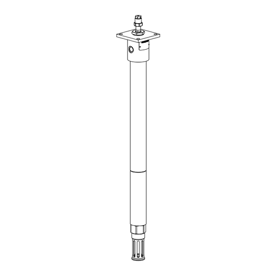
Ultra high pressure power-master iii pump tube

Advertisement

User and maintenance instructions
Ultra high pressure
Power-Master III pump tube
Models 85304 and 85305, series "A"
Date of issue
November 2022
Form number
403352
Version
3

Advertisement

Table of Contents
loading
Need help?

Need help?

Do you have a question about the SKF A Series and is the answer not in the manual?

Questions and answers

Summary of Contents for Lincoln SKF A Series

  • Page 1 User and maintenance instructions Ultra high pressure Power-Master III pump tube Models 85304 and 85305, series “A” Date of issue November 2022 Form number 403352 Version...
  • Page 2: Table Of Contents

    Contents Declaration of Conformity* U.K. Declaration of Conformity* Safety* Product specification Overview Title Model chart Dimensions Performance chart: models 2390 and 2391 (250:1 ratio) Performance chart: models 2392 and 2393 (140:1 ratio) Performance chart: models 2394 and 2395 (70:1 ratio) Air motor attachment Maintenance and repair Disassembly...
  • Page 3: Declaration Of Conformity

    I, the undersigned of Lincoln Industrial Corporation, do hereby declare that the equipment specified above, in its intended use, conforms to the requirements of the above directives and harmonized standards at the time of placing the above product on the market...
  • Page 4: U.k. Declaration Of Conformity

    I, the undersigned of Lincoln Industrial Corporation, hereby declare that the equipment specified above, in its intended use, conforms with all requirements of the U K legislation Supply of Machinery (Safety) Regulations 2008 No 1597 by the time of placing it on the market...
  • Page 5: Safety

    Safety* Explanation of signal WARNING  Do not allow any body part words for safety to be trapped by equipment The assembly must be installed, maintained Body parts can be crushed and repaired exclusively by persons familiar by subassemblies during with the instructions operation NOTE...
  • Page 6: Product Specification

    Overview Ultra high pressure pump tubes are designed specifically for oil well services such as wire line and plug valve applications In wire line applications, these pumps are used to seal against the well head pressure as the well is being logged or perforated In plug valve applications they are used to pump heavy grease into the valve or “Christmas tree valves”...
  • Page 7: Title Model Chart

    Fig. 1 Airmotor Ø 3 (88,9 mm) Pump tube Dimensions Pump tube Air motor Dimension “A” Dimension “B” Ø 2 85304 84808 61 in (154.9 mm) in (85.7 mm) (66,7 mm) 84806 61 in (154.9 mm) in (85.7 mm) 84804 in (152.7 mm) in (85.7 mm) 85305...
  • Page 8: Performance Chart: Models 2390 And 2391 (250:1 Ratio)

    Performance chart: models 2390 and 2391 (250:1 ratio) Delivery pressure (psi (bar)) Air consumption (scfm (m /min)) 20 000 (1 380) (5,6) 80 psi 18 000 (5,52 bar) (5,1) 80 psi (1 241) (5,52 bar) 16 000 (4,5) (1 103) 60 psi 14 000 60 psi...
  • Page 9: Air Motor Attachment

    1 Refer to fig. 3. Tightly attach tie rods to air technician motor (use short threaded end of tie rods) Contact a Lincoln service center for more 2 Mount air motor on top of pump tube Relieve pressure from pump and supply lines...
  • Page 10: Priming Tube Removal

    Priming tube removal Fig. 4 1 Refer to fig. 4 Insert pump tube into a workbench mounted vise assembly able to withstand torquing force exceeding 1 100 ft lbf (1 491 Nm) 2 Using a strap wrench, remove priming tube (21) from priming tube adapter (22) 3 Remove cotter pin (19) from priming plunger portion of priming check and plunger (17) and priming plunger nut (20)
  • Page 11: Pump/Adapter Tube Disassembly

    Pump tube disassembly Fig. 5 In most cases, pump tube repair involves priming check and plunger (17), bushing and plunger (1) or plunger rod (5) Repair procedure in part requires removing adapter tube (23) and priming tube adapter (22) from pump tube (25) In these cases, leave pump tube (25) attached to outlet body (11) 1 Refer to fig.
  • Page 12: Outlet Body And Plunger

    Outlet body and plunger Fig. 6 1 Unscrew plunger rod (5) from plunger (connecting) rod assembly (26) (Fig. 6), (→ fig. IPB 1, pg. 13) 2 Unscrew plunger (connecting) rod assembly (26) from bushing and plunger (1) 3 Remove check ball (2), pin (3) and check ball (4) from bushing and plunger (1) 4 Unscrew coupler (16) from bushing and plunger (1)
  • Page 13 Fig. IPB 1...
  • Page 14: Service Parts

    Table 1 Service parts Model Model Item no Description 85304 85305 Bushing and plunger 272143 272143 Check ball (0 375 in (9.5 mm)) 66007 66007 13237 13237 Check ball (0 625 in (15.8 mm)) 272135 272135 Plunger rod 272142 272142 Wave washer 66893 66893...
  • Page 15 Fig. IPB 2 6 (x 2) 6 (x 2) 6 (x 2) Torque to 1 000 to 1 100 ft lbf (1 356 to 1 491 Nm). Torque to 250 to 275 ft lbf (339 to 373 Nm) Torque to 20 to 22 ft lbf (27 to 30 Nm) Torque to 150 to 160 ft lbf (203 to 217 Nm) Torque to 130 to 150 ft lbf (176 to 203 Nm) Torque to 60 to 65 ft lbf (81 to 88 Nm)
  • Page 16: Warranty

    ® SKF and Lincoln are registered trademarks of the SKF Group © SKF Group 2022 The contents of this publication are the copyright of the publisher and may not be reproduced (even extracts) unless prior written permission is granted Every care has been taken to ensure the accuracy...

This manual is also suitable for:

Skf 85304Skf 85305

Table of Contents