
Subscribe to Our Youtube Channel
Related Manuals for MRC CM-100M3


Summary of Contents for MRC CM-100M3
- Page 1 Operation Manual of Rotor Beater Mill CM-100M3 3, Hagavish st. Israel 58817 Tel: 972 3 5595252, Fax: 972 3 5594529 mrc@mrclab.com MRC. 6.23...
-
Page 2: Table Of Contents
Content 1.0 Notes on the Manual ........................3 2.0 Safety..............................3 2.1 General Instructions ........................3 2.2 Warning ............................3 2.3 Repair ............................3 2.4 Safety Instructions ........................3 3.0 Transportation and Installation ..................... 4 3.1 Packing ............................4 3.2 Transportation ..........................4 3.3 Storage ............................ - Page 3 6.5 Wear ............................17 6.6 Testing ............................17 6.7 Copyright ..........................17 6.8 Modification ..........................17 Appendix Instrument trouble shooting list ..................18...
-
Page 4: Notes On The Manual
➢ Please use it normally MRC shall not be liable for any personal injury or damage to the equipment due to failure to comply with the safety instructions No changes can be made to the instrument, and use the accessories and fittings approved by MRC. -
Page 5: Transportation And Installation
To avoid damage to electronic and mechanical parts of the instrument, the machine may not be knocked, shaken or thrown during transport. ➢ Temperature Change If CM-100M3 is subjected to sharp temperature change (such as in air transport), the formation of condensate should be prevented to avoid damage to electronic and mechanical components. ➢... -
Page 6: Ambient Temperature
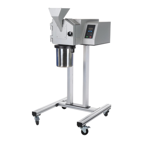
The CM-100M3 is able to handle large batches of material. After grinding, open the grinding chamber door then the rotary knife and bottom sieve can be removed for easy cleaning by the operator. The CM-100M3 is suitable for continuous grinding of the same material and can be used for periodic grinding. Features:... -
Page 7: Electrical Parameters
Fig 4.1.3.1 4.2 Electrical Parameters Rated voltage:380V, 50/60Hz Rated power:3.7KW Motor speed:3000~10000rpm, adjustable continuously Feed Size 4.3 CM-100M3≤25mm 4.4 Collecting Bucket The max volume of collecting bucket is up to 5 L. 4.5 Instrument Size ⚫ Grinding chamber(with motor):500x570x270 mm ⚫... -
Page 8: Instrument Operation
5.0 Instrument Operation 5.1 Instrument Units(Fig 5.1.1~Fig 5.1.3) Fig.5.1.1 (Accessories of rotor beater CM-100M3 grinding set(Fig 5.1.2 (CM-100M3-1) (CM-100M3-2) (CM-100M3-3) (CM-100M3-4) (CM-100M3-5) Fig 5.1.2... -
Page 9: Units Function List
Power supply for the mill 5.3 Open/Close Grinding Chamber Door (Fig 5.3.1) Please open the door only after CM-100M3 stops working Please grab handle B and turn it anticlockwise, then the door of grinding chamber is unlocked and can be opened... -
Page 10: Install/Disassemble The Rotor Beater Grinding Set Accessories(Fig 5.4.1~5.4.6
H when they are correctly positioned. Refer to Fig 5.6.2~5.6.4 Step 3:Install the rotor CM-100M3-3 Insert the CM-100M3-3 into shaft K and press it into the innermost place. Fix the CM-100M3-3 to the drive shaft K with a piece of outer hexagonal bolt T(M8×90), refer to Fig 5.6.5~5.6.6... -
Page 11: Collecting Bucket Installation (Fig 5.5
Fig 5.4.1 Fig 5.4.3 Fig 5.4.4 CR200-3 Fig 5.4.5 Fig 5.4.6 5.5 Collecting Bucket Installation (Fig 5.5) ⚫ Hang the collecting bucket C ⚫ Locking clamp W Fig 5.7... -
Page 12: Control Panel(Fig 5.6
The symbol appears when the door is Door open symbol open and disappears when the door is closed. Feed Sample Materials 5.8 Start the CM-100M3 at first, then start feeding the sample material. Note Excess sample amount will lead to instrument and components damages. ➢ ➢... -
Page 13: Preparation Before Grinding
Do not feed multi-shaped materials as they may bounce back and cause you injury. ➢ 5.11 Stop the Instrument Press“STOP ” key to stop the instrument. Using the Cyclone 5.12 ,CM-100M3 can connect with cyclone and vacuum to collect some light samples eg: plastic bags, paper bags and packing material for milk products... -
Page 14: Install The Cyclone
4. Lock 5.5L collecting bucket Hopper bracket and handwheel Support bar Hopper connecting with CM-100M3 sample outlet (incl 4 pcs of hexagon socket button head screws (M4x8 Support block of cyclone(incl 4 pcs of hexagon socket head screws M6x12,1 pc of... -
Page 15: Install The Vibratory Feeder Vf200
Vacuum cleaner connection port Fig 5.13.2.2 5.14 Install the Vibratory Feeder VF200 5.14.1 Remove Screws for Transportation (Fig 5.14.1) In order to ensure that the internal mechanical moving parts of the instrument are not damaged during transport, the instrument is shipped with 4 hexagonal screws installed at the bottom of the instrument. - Page 16 V1, V2 positions. (Fig. 5.14.2.2) Fig 5.14.2.2 Step 5: Place the support plate along with VF200 on the main machine CM-100M3 grinding chamber and fasten by 3pcs. of M6x16mm hexagon socket head cap screws in position V3 (Fig 5.14.2.3-5.14.2.4)
-
Page 17: Routine
Open the grinding chamber door and take out all grinding kits Press“START”key and the instrument cannot be activated Close grinding chamber door and press “START”, the instrument is activated Note Please contact MRC and inform the relative distributor if the instrument can still run... -
Page 18: Maintenance 6.3
Maintenance 6.3 In order to ensure the reliable operation of the CM-100M3, the following maintenance shall be carried out daily after use The grinding kit, rotor and sieve should be wiped dry after cleaning and placed in a dry ⚫... - Page 19 Appendix Instrument trouble shooting list Fault Fault Reason Solution Phenomenon 1. Check if the power supply Replace or test the power fault supply 2. Check if the power supply Replace the power supply switch fault switch 3. Check if the power supply Replace the power supply Power on but no socket fault...
- Page 20 leak 2. The hopper didn’t install Reinstall the hopper properly 1. Seal ring aged or worn Replace a new seal ring Discharge ring 2. The discharge ring didn’t leak Reinstall the discharge ring install properly...
Need help?
Do you have a question about the CM-100M3 and is the answer not in the manual?
Questions and answers