Table of Contents
Advertisement
Quick Links
Advertisement
Table of Contents

Related Manuals for MRC CALI-1200


Summary of Contents for MRC CALI-1200
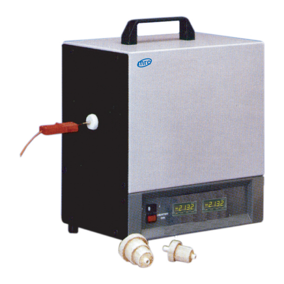
- Page 1 Installation, Operation and Maintenance Instructions 1200 °C Thermocouple Calibration Furnace - Model: CALI-1200+2132 Controller CALI-1200 + 2132 Controller 3, Hagavish st. Israel 58817 Tel: 972 3 5595252, Fax: 972 3 5594529 MRC.5.21 mrc@mrclab.com...
-
Page 2: Table Of Contents
Contents This manual is for guidance on the use of the MRC product specified on the front cover. This manual should be read thoroughly before unpacking and using the furnace or oven. The model details and serial number are shown on the back of this manual. - Page 3 5.0 Maintenance General Maintenance Maintenance Schedule 5.2.1 Cleaning Calibration After-Sales Service Recommended Spare Parts and Spare Parts Kit Power Adjustment 6.0 Repairs and Replacements Safety Warning - Disconnection from Power Supply Safety Warning - Refractory Fibre Insulation Temperature Controller Replacement Solid-State Relay Replacement Thermocouple Replacement Element Replacement...
-
Page 4: Symbols And Warnings
1.0 Symbols and Warnings 1.0 Symbols and Warnings Switches and Lights Instrument switch: when the instrument switch is operated the temperature control circuit is energised. Heat light: the adjacent light glows or flashes to indicate that power is being supplied to the elements. General Warnings DANGER –... -
Page 5: Installation
2.0 Installation 2.0 Installation Unpacking and Handling Unpack the product and remove the transit clamp from the working end of the product as follows: loosen the locking nut on the central clamp bolt; turn the bolt clockwise with a screwdriver to release the force on the clamping device;... -
Page 6: Electrical Connections
2.0 Installation Depending on the application of the product, it may be appropriate to position it under an extraction hood. Ensure the extraction hood is switched on during use. Ensure that the product is placed in such a way that it can be quickly switched off or disconnected from the electrical supply. - Page 7 2.0 Installation The supply should be fused at the next size equal to, or higher than the current on the label. A table of the most common fuse ratings is also given towards the back of this manual. When the mains cable is factory fitted, internal fuses are also fitted. It is essential that the operator ensures that the product is correctly fused.
-
Page 8: 2132 Controller
3.0 2132 Controller 3.0 2132 Controller Description The 2132 Controller is made by Eurotherm, and is fitted and configured by MRC for immediate use. It is a digital instrument with PID control algorithms. The 2132 Controller features: Easy use as a simple temperature controller, where on setting the required tem- perature the controller immediately attempts to reach and maintain it. -
Page 9: 2132 Controller Operation
3.0 2132 Controller 3.2.2 2132 Controller Operation Alarm Light Page Scroll D Down Display When switched on, the controller lights up, goes through a short test routine and then displays the measured temperature or the over-temperature setpoint. The page key allows access to parameter lists within the controller. -
Page 10: Stopping And Starting Control
3.0 2132 Controller 3.2.5 Stopping and Starting Control It is possible to stop and start the controller without altering the setpoint. Press scroll until the legend 'm-A' (manual/ auto) appears. In this controller, manual means OFF and auto means ON. Press down or up once to show the current on/ off state: 'mAn' for OFF and 'Auto' for ON. -
Page 11: Operating With The Timer
3.0 2132 Controller Fig 1 - Control without Ramp-to-Setpoint Fig 2 - Control with Ramp-to-Setpoint Temperature Time Setpoint WSP Working Setpoint Actual Temperature Operating with the Timer This controller can be used as a process timer allowing timed heating or timed delay, according to the options in the table. - Page 12 3.0 2132 Controller Timer Mode Description Timer Light The timer starts timing when the actual temperature is within 1 °C On while temperature is mode 1 of the setpoint. At the end of the reaching setpoint. On during timing period, control switches Timed dwell and the timing period.
-
Page 13: Setting The Timer Mode
3.0 2132 Controller 3.3.1 Setting the Timer Mode Scroll to 'tm.OP'; use to view and alter the mode. The mode shows as 'OPt.1' to 'OPt.5'. It is not possible to alter the mode while the timer is operating; if the mode cannot be altered, scroll to the 'StAt' parameter and set its value to OFF. -
Page 14: Stopping The Timer
3.0 2132 Controller Fig 3 - Timer Modes Temperature Time Setpoint Working Setpoint (if setpoint ramp rate active) Actual Temperature M245 Modes 2, 4 & 5 Modes 1 & 3 Timing Mode 5 Reaching Temperature Modes 1 & 2 Modes 1 & 2 Modes 3 &... -
Page 15: End Of Time Period
3.0 2132 Controller though it has reached the end of the time period. 3.3.5 End of Time Period Modes 1 and 3: heating stops at the end of timing; the 'm-A' parameter changes to 'mAn'. Modes 2 and 4: heating continues at the end of timing; the 'm-A' parameter remains at 'Auto'. - Page 16 In many models the power limit setting depends on the supply voltage; usually the furnace or oven manual contains details: if in doubt, contact MRC for advice. The power limit parameter does not apply to the over-temperature controller, if fitted. Altering...
- Page 17 3.0 2132 Controller User Calibration The controller is calibrated for life at manufacture against known reference sources, but there may be sensor errors or other system errors. User calibration allows compensation for such errors and this controller allows for a user 2-point calibration. This setting is password protected to avoid accidental alteration.
-
Page 18: Audible Alarm
3.0 2132 Controller User Temperature Reading Factory Temperature Reading UC User Calibration UF Factory Calibration Audible Alarm If an audible alarm is supplied for use with the timer function, then it is normally configured to sound at the 'End' condition and to go off when the alarm is acknowledged as given in section 3.3.6. -
Page 19: Navigation Diagram
3.0 2132 Controller Navigation Diagram... - Page 20 3.0 2132 Controller HL Home List Input List OL Output List AL Access List Measured temperature; use arrow keys to access setpoint Output power (read only) Present only if SPrr in use Manual/Auto (mAn = off, Auto = on) Setpoint ramp rate OFF or value Timer mode Time remaining Dwell time for timer...
-
Page 21: Operation
4.0 Operation 4.0 Operation Operating Cycle This product is fitted with an instrument switch which cuts off power to the control circuit. Connect the product to the electrical supply. Turn on the instrument switch to activate the temperature controllers. The controllers illuminate and go through a short test cycle. -
Page 22: Instructions For Use As A Calibration Furnace
In the CALI-1200 the reference thermocouple is built in and has its own indicator marked Reference Temperature. It is located within the work tube such that its tip is positioned close to that of the thermocouple to be tested in the part of the tube which has the most uniform temperature. -
Page 23: Maintenance
5.0 Maintenance 5.0 Maintenance General Maintenance Preventive rather than reactive maintenance is recommended. The type and frequency depends on the product use; the following are recommended. Maintenance Schedule CUSTOMER QUALIFIED PERSONNEL DANGER! ELECTRIC SHOCK. Risk of fatal injury. Only electrically qualified personnel should attempt these maintenance procedures. - Page 24 5.0 Maintenance Seals (if fitted) Check all seals and O-rings and clamps Performance Element Circuit Electrical measurement Measure the current drawn on each Power Consumption phase / circuit Check whether the cooling fans are work- Cooling Fans (if fitted)
-
Page 25: Cleaning
Recommended Spare Parts and Spare Parts Kit MRC can supply individual spare parts or a kit of the items most likely to be required. Ordering a kit in advance can save time in the event of a breakdown. Each kit consists of a pair of thermocouples, one solid state relay and one heating element. - Page 26 5.0 Maintenance In some cases the supply voltage may be outside the range 220-240 V or the 3-phase equivalent, the power limit parameter may be set to a value other than 100%. Do not increase the value to 100%, see section 9.0 for details of power limit settings.
-
Page 27: Repairs And Replacements
(www.ecfia.eu). Further information can be provided on request. Alternatively, MRC Service can quote for any repairs to be carried out either on site or at the MRC factory. Temperature Controller Replacement Refer to the controller instructions for more information on how to replace the... -
Page 28: Solid-State Relay Replacement
This involves dismantling the outer case, disconnecting the electrical leads and removing the inner product chamber. Make a sketch of the layout inside the back panel before attempting this. It is recommended that you contact MRC for advice before starting the operation. -
Page 29: Fault Analysis
7.0 Fault Analysis 7.0 Fault Analysis Furnace Does Not Heat Up The HEAT The heating element Check also that the SSR is working light is ON has failed correctly The controller shows a The HEAT The thermocouple has broken or has very high temperature light is OFF a wiring fault... -
Page 30: Product Overheats
7.0 Fault Analysis Product Overheats Product only heats up The controller when the instrument shows a very high The controller is faulty switch is ON temperature The thermocouple may be The controller faulty or may have been shows a low removed out of the heating temperature chamber... -
Page 31: Wiring Diagrams
8.0 Wiring Diagrams 8.0 Wiring Diagrams 183/4/1006... -
Page 32: Fuses And Power Settings
115 V position and the furnace is connected to a 220-240 V supply. Model Phases Volts Supply Fuse CALI-1200 1-phase 220-240 10 A Power Settings The setting for the power limit parameter in the controller (OP.Hi) should be 100% for the model listed in this manual. -
Page 33: Specifications
10.0 Specifications 10.0 Specifications MRC reserves the right to change the specification without notice. Work Tube Work Tube Model Temp Power Weight Bore (mm) Length (mm) (°C) (kW) (kg) Thermocouple Calibration Furnace CALI-1200 1200 10.1 Environment The models listed in this manual contains electrical parts and should be stored and used... - Page 34 Notes Service Record Engineer Name Date Record of Work...
- Page 35 The products covered in this manual are only a small part of the wide range of ovens, chamber furnaces and tube furnaces manufactured by MRC for laboratory and industrial use. For further details of our standard or custom built products please contact us at the address below, or ask your nearest stockist.
Need help?
Do you have a question about the CALI-1200 and is the answer not in the manual?
Questions and answers