
Subscribe to Our Youtube Channel
Related Manuals for MRC CENVCC-3


Summary of Contents for MRC CENVCC-3
- Page 1 CENVCC-3 Table Vacuum Centrifugal concentrator Instruction & Using Manual Please read this manual carefully before use 3, Hagavish st. Israel 58817 Tel: 972 3 5595252, Fax: 972 3 5594529 mrc@mrclab.com MRC.8.22...
-
Page 2: Table Of Contents
Content Ⅰ、FEATURES AND USES ................1 Ⅱ、WORKING PRINCIPLE ................2 Ⅲ、VACUUM CONCENTRATOR SPECIFICATION ........2 Ⅳ、ROTOR SPECIFICATION ................ 4 Ⅴ、PRECAUTION .....................5 Ⅵ、APPEARANCE AND STRUCTURE ............6 Ⅶ、WORKING PROCEDURE ................ 7 VIII、TROUBLES & SOLUTIONS ..............8 IX、INSTALLATION..................9 X、 MAINTENANCE..................10 XI、WARRANTY...................11 XII、CERTIFICATE OF CONFORMITY..........12 XIII、PACKING LIST...................13... -
Page 3: Ⅱ、Working Principle
一、Features and Uses CENVCC-3 is a microcomputer-controlled desktop vacuum concentrator. made by full steel body. the surface is spray-coated, with good rigidity and high strength. It has novel shape, beautiful appearance, low noise, rising temperature slowly, safety and reliability etc This machine use frequency conversion motor. -
Page 4: Ⅳ、Rotor Specification
Noise: ≤50dB Power: AC220V±10% 50Hz 10A Machine size: 430 mm×400 mm×330 mm (L×W×H) Net Weight: 35Kg Ⅳ、Rotor Specification Rotor Number Capacity Max Speed Max RCF No.1 62×1.5ml 1800r/min 409×g Angle rotor No.2 135×0.5ml 1800r/min 273×g Ⅴ、PRECAUTION 1. In order to safety working and correct centrifuging, please take the machine in a solid, shockproof and horizontal table, please ensure the four feet equal force. -
Page 5: Ⅵ、Appearance And Structure
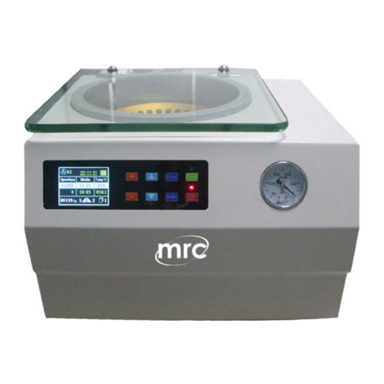
9. Check whether the external power supply meets the requirements, the instrument is reliable grounding. 10. No moving and No lid-open during the centrifuge running, Do not open the lid when the motor and rotor are not completely stopped. 11. The instrument or rotor disabled for three month, please running at low speed 10min, then allow to work on high speed. - Page 6 Information window 2、Speed window 3、RCF window 4、Time window 5、Rotor no. 6、Acceleration gear 7、Deceleration gear 8、 Program group number 9 、 Setting key 10 、 increasing key 11 、 instantaneous centrifugal key 12、Running indicator 13、Start key 14、 Confirmation key 15、Reduction key 16、Speed/Centrifugal Force Mode Switching Key 17、Stop indicator 18、Stop key/open key 4 / 17...
-
Page 7: Ⅶ、Working Procedure
Ⅶ、Working procedure 1) the centrifuge placed on the platform, visual to balance, shake and check whether the centrifuge placed smoothly. 2) confirm the placement is stable, turn on the power, press the power switch, press the "stop / open" button, the lid can be opened. 3) Open the lid, the selected rotor gently placed on the motor shaft, screw on the screw so that the rotor and the motor shaft tightly connected together (Note: it should be careful and gentle, to avoid shaking and pull up and down, so as not to Damage the motor... -
Page 8: Troubles & Solutions
use of larger volume of the angle rotor or swing-out rotor, you can choose a little bit of the slows, the other can choose a little faster file Bit. Generally recommended to use 5 files; Finally press "Enter" to confirm. 7) When the "Short"... -
Page 9: Installation
Key damaged replace Motor damage or leakage replace Running but not speed, the manufacturers machine has strange sound or Control system or motor failure maintenance smell The machine with fault prompt, when the machine fails, the "display window" will display the following items: Unbalance Over-speed Lid-open... -
Page 10: Maintenance
1、Out of the box check a) Before receiving the instrument, you should carefully check for transport damage. If so, please reject the goods and inform the Company in writing and take pictures of the damaged machine. b) check whether the goods match the order list, if not, please contact the company. c) 1.3, remove the packaging, and remove the contents of the centrifugal chamber. - Page 11 1. 1. warranty: 1 year Vacuum centrifugal concentrator Free warranty is one year since the date of purchase upon non-human damage. Technical guide for the whole life. 2. the company supporting a variety of rotor quality assurance period of one year. the company does not assume any responsibility the following: ...
-
Page 12: Certificate Of Conformity
XII、CERTIFICATE OF CONFORMITY Table Vacuum Concentrator CERTIFICATE OF CONFORMITY Max RPM:1800r/min Max RCF: 409×g Serial number: This product has been tested and approved. Inspectors:... -
Page 13: Packing List
XIII、PACKING LIST Packing List Name Specification Qty. Mark Table Vacuum 1Set 一 concentrator Accessories & tools 二 Power plug 1Pcs Angle rotor 1Set 62×1.5ml Vacuum Pump 1set Cold Trap 1set Document 三 Instruction manual This manual Certificate of This manual conformity Packing list This manual... - Page 14 Cold Trap Operating Instructions 1. The overview of the cold trap is as follows:: Basic parameters of cold trap: Power supply: 220V ± 22V power: 500W Overall dimension: 665 × four hundred and ten × 420 (long) × wide × Height in mm Pipe joint size: φ...
- Page 15 1. Temperature display window 2. Defrosting key 3. Compressor operation indicator 4. Compressor start / stop button 3、The operating procedures of the instrument are as follows: 1. Place the cold trap on the table stably, and the table shall be flat without strong vibration and strong heat source.
- Page 16 display is P0. Press the setting key again to set the required starting temperature through the up and down keys; P1 set stop temperature: press the set key to enter the internal menu, the digital display is P0, switch to P1 through the up and down keys, and then press the set key to set the required stop temperature through the up and down keys;...
Need help?
Do you have a question about the CENVCC-3 and is the answer not in the manual?
Questions and answers