Table of Contents
Advertisement
Quick Links
Advertisement
Table of Contents

Related Manuals for DFI PIC-Q170/H110


Summary of Contents for DFI PIC-Q170/H110
- Page 1 PIC-Q170/H110 Full-Size PICMG 1.3 User’s Manual A51900943...
-
Page 2: Trademarks
PIC-Q170/H110 www.dfi.com Copyright FCC and DOC Statement on Class B This publication contains information that is protected by copyright. No part of it may be re- This equipment has been tested and found to comply with the limits for a Class B digital produced in any form or by any means or used to make any transformation/adaptation without device, pursuant to Part 15 of the FCC rules. -
Page 3: Table Of Contents
PIC-Q170/H110 www.dfi.com Table of Contents Installing the M.2 Module ................25 Copyright ........................2 Battery......................26 Trademarks ........................2 Chapter 3 - BIOS Setup ....................27 FCC and DOC Statement on Class B ................2 Overview ......................27 Main ........................28 Notice: ......................... -
Page 4: About This Manual
PIC-Q170/H110 www.dfi.com About this Manual Static Electricity Precautions An electronic file of this manual is included in the CD. To view the user’s manual in the CD, in- It is quite easy to inadvertently damage your PC, system board, components or devices even sert the CD into a CD-ROM drive. -
Page 5: About The Package
About the Package The package contains the following items. If any of these items are missing or damaged, please contact your dealer or sales representative for assistance. • One PIC-Q170/H110 board • Two Serial ATA cables (500mm) • One DVD •... -
Page 6: Chapter 1 - Introduction
Chapter 1 - Introduction PIC-Q170/H110 www.dfi.com Chapter 1 - Introduction ► Specifications SYSTEM Processor 7th Generation Intel CoreTM Processors, LGA1151: INTERNAL I/O Serial 2 x RS-232/422/485 (2.54mm pitch) ® • Intel CoreTM i7-7700 Processor, Four Core, 8M, 3.6GHz (4.2GHz), 65W 2 x RS232 (2.54mm pitch) -
Page 7: Features
Chapter 1 - Introduction PIC-Q170/H110 www.dfi.com ► Features Watchdog Timer Wake-On-PS/2 The Watchdog Timer function allows your application to regularly “clear” the system at the set This function allows you to use the PS/2 keyboard or PS/2 mouse to power-on the system. -
Page 8: Chapter 2 - Hardware Installation
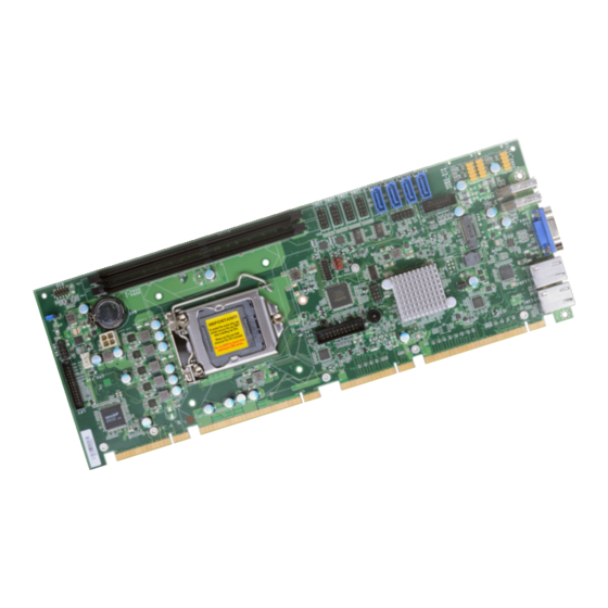
Chapter 2 - Hardware Installation PIC-Q170/H110 www.dfi.com Chapter 2 - Hardware Installation ► Board Layout ► Standby Power LED Standby Power LED Standby Power LED LAN 1 Socket LGA1151 ASM1085 Buzzer DVI-D Note LAN 2 Intel SMBus Intel I211AT Q170/H110... -
Page 9: System Memory
Chapter 2 - Hardware Installation PIC-Q170/H110 www.dfi.com ► System Memory ► System Memory Installing the DIMM Module Before installing the memory module, please make sure that the following safety cautions are well-attended. 1. Make sure the PC and all other peripheral devices connected to it has been powered down. -
Page 10: Removing The Dimm Module
Chapter 2 - Hardware Installation PIC-Q170/H110 www.dfi.com ► System Memory ► Installing the DIMM Module ► System Memory Removing the DIMM Module Please follow the steps below to install the memory card into the socket. Step 1: Press the eject tabs at both ends of the socket outward and downward to release them from the Please follow the steps below to remove the memory card from the socket. -
Page 11: Cpu
Chapter 2 - Hardware Installation PIC-Q170/H110 www.dfi.com ► CPU Installing the CPU 1. Make sure the PC and all other peripheral devices connected to it have been powered The system board is equipped with a surface mount LGA 1151 socket. This socket is exclu- down. - Page 12 Chapter 2 - Hardware Installation PIC-Q170/H110 www.dfi.com ► CPU ► Installing the CPU ► CPU ► Installing the CPU Load lever 5. Lift the load lever and the load 7-2. Two keys on the sock- Alignment key plate all the way up as shown in et and notches on the photo.
-
Page 13: Installing The Fan And Heat Sink
Chapter 2 - Hardware Installation PIC-Q170/H110 www.dfi.com ► CPU Installing the Fan and Heat Sink The CPU must be kept cool by using a CPU fan with heat sink. Without sufficient air circula- 4. Screw tight two of the spring screws at opposite corners into the mounting holes. And tion across the CPU and heat sink, the CPU will overheat damaging both the CPU and system then proceed with the other two spring screws. -
Page 14: Jumper Settings
Chapter 2 - Hardware Installation PIC-Q170/H110 www.dfi.com ► Jumper Settings Clear CMOS If any anomaly of the followings is encountered — a) CMOS data is corrupted; b) you forgot the supervisor or user password; c) failure to start the system due to BIOS mis-configuration —... -
Page 15: Rear I/O Ports
Chapter 2 - Hardware Installation PIC-Q170/H110 www.dfi.com ► Rear I/O Ports Graphics Display ▼ USB 1 ▼ LAN 1 ▼ LAN 2 ▼ VGA ▲ USB 2 The rear panel I/O ports consist of the following: • 2 LAN ports (LAN 1 & LAN 2) •... -
Page 16: Usb Ports
USB allows data exchange between your computer and a wide range of simultaneously acces- The LAN ports allow the system board to connect to a local area network by means of a net- sible external Plug and Play peripherals. The PIC-Q170/H110 is equipped with two onboard work hub. -
Page 17: Internal I/O Connectors
Chapter 2 - Hardware Installation PIC-Q170/H110 www.dfi.com ► Internal I/O Connectors COM (Serial) Ports ▼ COM Port Pin Assignment RS232 RS422 Full Duplex RS485 DCD- TXD- Data- TXD+ Data+ RXD+ N.C. DTR- RXD- N.C. COM 4 (left) COM 2 (left) -
Page 18: Digital I/O Connector
Chapter 2 - Hardware Installation PIC-Q170/H110 www.dfi.com ► Internal I/O Connectors ► Internal I/O Connectors Digital I/O Connector SATA (Serial ATA) Connectors Digital I/O Connector SATA 3/2/1/0 (from left to right) The 8-bit Digital I/O connector provides powering-on function to external devices that are The Serial ATA (SATA) connectors are used to connect the Serial ATA device. -
Page 19: Cooling Fan Connectors
Chapter 2 - Hardware Installation PIC-Q170/H110 www.dfi.com ► Internal I/O Connectors ► Internal I/O Connectors Cooling Fan Connectors Chassis Intrusion Connector ▼ Chassis Intrusion Connector 3-pin Fan Connector 4-pin PWM Fan (System Fan 1) Connector (CPU Fan) ▼ 3-pin Fan Pin Assignment ▼... -
Page 20: Front Panel Connector
Chapter 2 - Hardware Installation PIC-Q170/H110 www.dfi.com ► Internal I/O Connectors ► Internal I/O Connectors Front Panel Connector LPT Connector PWR-LED ATX-SW ▼ LPT Pin Assignment Assignment Assignment ◄ Front Panel Connector Strobe Auto Feed ▼ LPT Connector Data_Out_0 ERP_WAKE... -
Page 21: Dvi-D Connector
Chapter 2 - Hardware Installation PIC-Q170/H110 www.dfi.com ► Internal I/O Connectors ► Internal I/O Connectors DVI-D Connector KB/MS Connector ◄ DVI-D Connector ▼ KB/MS Cable ▼ KB/MS Connector MSCLK KBCLK MSDATA KBDATA ◄ PIC-DVI Card with Cable DVI Rear Port... -
Page 22: Lpc Connector
LPC Connector External COM Port Module The external COM port modules — EXT-RS232 and EXT-RS485 — are designed by DFI’s pro- prietary technology, and support four additional COM ports per module. The EXT-RS232/RS485 card is connected to the motherboard via the LPC connector and secured by a standoff as il- lustrated below. -
Page 23: Smbus Connector
Chapter 2 - Hardware Installation PIC-Q170/H110 www.dfi.com ► Internal I/O Connectors ► Internal I/O Connectors SMBus Connector USB Headers ◄ USB 3/4 (Q170 only) ◄ SMBus Connector ▼ USB 5-6 ▼ USB 2.0 Pin Assignment ▼ USB 3.0 Pin Assignment... -
Page 24: Dc Power
Chapter 2 - Hardware Installation PIC-Q170/H110 www.dfi.com ► Internal I/O Connectors ► Internal I/O Connectors 12V DC Power Audio Connector +12V Audio Link BCLK +12V Power Connector ► Audio Link RST- ◄ Audio Connector Pin Assignment Audio Link SDI0 Audio Link SDO Audio Link SYNC Connect a 4-pin power cord to the vertical type power connector for DC supply. -
Page 25: Expansion Slot
Chapter 2 - Hardware Installation PIC-Q170/H110 www.dfi.com ► Internal I/O Connectors ► Internal I/O Connectors ► Expansion Slots Expansion Slot Installing the M.2 Module Before installing the M.2 module into the M.2 socket, please make sure that the following safety cautions are well-attended. -
Page 26: Battery
Chapter 2 - Hardware Installation PIC-Q170/H110 www.dfi.com ► Internal I/O Connectors ► Expansion Slots ► Internal I/O Connectors Battery Please follow the steps below to install the card into the socket. Step 1: Insert the card into the socket at an angle while making sure the notch and key are perfectly aligned. -
Page 27: Chapter 3 - Bios Setup
Chapter 3 - BIOS Settings PIC-Q170/H110 www.dfi.com Chapter 3 - BIOS Setup ► Overview Legends The BIOS is a program that takes care of the basic level of communication between the CPU and peripherals. It contains codes for various advanced features found in this system board. -
Page 28: Main
Chapter 3 - BIOS Settings PIC-Q170/H110 www.dfi.com ► Main ► Advanced The Main menu is the first screen that you will see when you enter the BIOS Setup Utility. The Advanced menu allows you to configure your system for basic operation. Some entries are defaults required by the system board, while others, if enabled, will improve the performance of your system or let you set some features according to your preference. -
Page 29: Acpi Configuration
Chapter 3 - BIOS Settings PIC-Q170/H110 www.dfi.com ► Advanced ACPI Configuration InsydeH2O Setup Utility Rev. 5.0 InsydeH2O Setup Utility Rev. 5.0 Advanced Advanced ACPI Configuration Determines the action tak- ACPI Configuration Support display logo with ACPI BGRT table. en when the system power Wake On LAN <Disabled>... -
Page 30: Cpu Configuration
Chapter 3 - BIOS Settings PIC-Q170/H110 www.dfi.com ► Advanced ► Advanced CPU Configuration Video Configuration Configure CPU processing related settings in this page. InsydeH2O Setup Utility Rev. 5.0 InsydeH2O Setup Utility Rev. 5.0 Advanced Advanced Select which of IGFX/PEG/PCI Graphics... -
Page 31: Audio Configuration
Chapter 3 - BIOS Settings PIC-Q170/H110 www.dfi.com ► Advanced ► Advanced Audio Configuration SATA Configuration InsydeH2O Setup Utility Rev. 5.0 InsydeH2O Setup Utility Rev. 5.0 Advanced Advanced C o n t r o l D e t e c t i o n o f t h e H D -... -
Page 32: Usb Configuration
Chapter 3 - BIOS Settings PIC-Q170/H110 www.dfi.com ► Advanced ► Advanced USB Configuration PCI Express Configuration InsydeH2O Setup Utility Rev. 5.0 InsydeH2O Setup Utility Rev. 5.0 Advanced Advanced U S B k e y b o a r d / m o u s e / s t o r a g e... -
Page 33: Me Configuration
Chapter 3 - BIOS Settings PIC-Q170/H110 www.dfi.com ► Advanced ► Advanced ME Configuration MEBX Configuration InsydeH2O Setup Utility Rev. 5.0 InsydeH2O Setup Utility Rev. 5.0 Advanced Advanced Enable/disable to flash ME re- MEBX Configuration Setting ME Configuration MEBX Configuration gion. -
Page 34: Active Management Technology Support
Chapter 3 - BIOS Settings PIC-Q170/H110 www.dfi.com ► Advanced ► Advanced Active Management Technology Support Debug Configuration This section configures Debug setting. InsydeH2O Setup Utility Rev. 5.0 InsydeH2O Setup Utility Rev. 5.0 Advanced Advanced When disabled AMT BIOS Fea- Enable it to output debug mes-... -
Page 35: Uefi Device Manager
Chapter 3 - BIOS Settings PIC-Q170/H110 www.dfi.com ► Advanced ► Advanced UEFI Device Manager SIO NUVOTON6106D Configure UEFI device with option ROM, such as LAN card, etc. Configure Super I/O settings in this submenu. Scroll by moving the cursor up or down to re- veal more options. - Page 36 Chapter 3 - BIOS Settings PIC-Q170/H110 www.dfi.com ► Advanced ► SIO NUVOTON6106D ► Advanced ► SIO NUVOTON6106D Smart Fan is a fan speed moderation strategy that depends on the current system tempera- PC Health Status ture. When the system temperature goes higher than the Boundary setting, the fan speed will This section displays the PC health status.
-
Page 37: Console Redirection
Chapter 3 - BIOS Settings PIC-Q170/H110 www.dfi.com ► Advanced Console Redirection COM1/COM2/COM3/COM4/Pci Serial Port 0:22:3 Configure individual COM port serial settings in the submenu. Configure COM port serial settings in the submenu. InsydeH2O Setup Utility Rev. 5.0 InsydeH2O Setup Utility Rev. -
Page 38: Security
Chapter 3 - BIOS Settings PIC-Q170/H110 www.dfi.com ► Security ► Boot InsydeH2O Setup Utility Rev. 5.0 InsydeH2O Setup Utility Rev. 5.0 Main Advanced Security Boot Exit Main Advanced Security Boot Exit Current TPM Device <TPM 2.0 (FTPM)> W h e n H i d d e n , d o n ’ t e x - Numlock <On>... - Page 39 Chapter 3 - BIOS Settings PIC-Q170/H110 www.dfi.com ► Boot ► Boot PXE Boot capability Legacy This field is only available when "Boot Type" is set to “UEFI Boot Type” or “Dual Boot Type”, Configure boot priorities in this submenu. Re-arrange the order by pressing -/+ or F5/F6 to and when "Network Stack"...
-
Page 40: Exit
BIOS with the flash utility. For updating Insyde BIOS in UEFI mode, you may refer to the how-to video at https://www.dfi.com/tw/knowledge/video/31. InsydeH2O Setup Utility Rev. -
Page 41: Overview
Chapter 4 - Intel AMT Settings PIC-Q170/H110 www.dfi.com Chapter 4 - Intel AMT Settings ► Enabling Intel AMT in the Insyde BIOS ® ► Overview 1. Power-on the system then press <Del> to enter the main menu of the Insyde BIOS. -
Page 42: Entering Management Engine Bios Extension (Mebx)
Chapter 4 - Intel AMT Settings PIC-Q170/H110 www.dfi.com ► Enabling Intel AMT in the Insyde BIOS ® ► Entering Management Engine BIOS Extension (MEBX) 4. In the Exit menu, select Exit Saving Changes or press F10, and then select Yes and press Enter. -
Page 43: Mebx
Chapter 4 - Intel AMT Settings PIC-Q170/H110 www.dfi.com ► MEBX ► MEBX Intel(R) ME General Settings Select Intel(R) ME General Settings under Main Menu and then press Enter. Main Menu Select MEBx Login under Main Menu and press Enter. A prompt that requires password input Intel(R) Management Engine BIOS Extension v11.0.0.0010/Intel(R) ME v11.8.55.3510... - Page 44 Chapter 4 - Intel AMT Settings PIC-Q170/H110 www.dfi.com ► MEBX ► Intel(R) ME General Settings ► MEBX ► Intel(R) ME General Settings Change ME Password Local FW Update If you want to change ME password, select Change ME Password and then press Enter. A Select Local FW Update then press Enter.
-
Page 45: Intel(R) Amt Configuration
Chapter 4 - Intel AMT Settings PIC-Q170/H110 www.dfi.com ► MEBX ► MEBX ► Intel(R) AMT Configuration Intel(R) AMT Configuration > SOL/Storage Redirection/KVM Select Intel(R) AMT Configuration under Main Menu and then press Enter. Intel(R) Management Engine BIOS Extension v11.0.0.0010/Intel(R) ME v11.8.55.3510 Intel(R) Management Engine BIOS Extension v11.0.0.0010/Intel(R) ME v11.8.55.3510... - Page 46 Chapter 4 - Intel AMT Settings PIC-Q170/H110 www.dfi.com ► MEBX ► Intel(R) AMT Configuration ► MEBX ► Intel(R) AMT Configuration > SOL/Storage Redirection/KVM > User Consent Intel(R) Management Engine BIOS Extension v11.0.0.0010/Intel(R) ME v11.8.55.3510 Intel(R) Management Engine BIOS Extension v11.0.0.0010/Intel(R) ME v11.8.55.3510 Copyright(C) 2003-16 Intel Corporation.
- Page 47 Chapter 4 - Intel AMT Settings PIC-Q170/H110 www.dfi.com ► MEBX ► Intel(R) AMT Configuration ► MEBX ► Intel(R) AMT Configuration > User Consent Password Policy Intel(R) Management Engine BIOS Extension v11.0.0.0010/Intel(R) ME v11.8.55.3510 Intel(R) Management Engine BIOS Extension v11.0.0.0010/Intel(R) ME v11.8.55.3510 Copyright(C) 2003-16 Intel Corporation.
- Page 48 Chapter 4 - Intel AMT Settings PIC-Q170/H110 www.dfi.com ► MEBX ► Intel(R) AMT Configuration > Network Setup Under the Intel(R) AMT Configuration menu, select Network Setup and then press Enter. Move the cursor to select a field and press Enter to display options.
- Page 49 Chapter 4 - Intel AMT Settings PIC-Q170/H110 www.dfi.com ► MEBX ► Intel(R) AMT Configuration ► MEBX ► Intel(R) AMT Configuration > Network Setup > Intel(R) ME Network Name Settings > Network Setup Dynamic DNS Update > TCP/IP Settings Select Enabled or Disabled then press Enter. When Dynamic DNS Update is Enabled, the fol- Under the Intel(R) ME Network Setup menu, select TCP/IP Settings and then press Enter.
- Page 50 Chapter 4 - Intel AMT Settings PIC-Q170/H110 www.dfi.com ► MEBX ► Intel(R) AMT Configuration > Network Setup > TCP/IP Settings DHCP Mode IPv4 Address Select Enabled or Disabled then press Enter. Please make sure there is a DHCP server in the Assign a valid and available IP address to the system.
- Page 51 Chapter 4 - Intel AMT Settings PIC-Q170/H110 www.dfi.com ► MEBX ► Intel(R) AMT Configuration ► MEBX ► Intel(R) AMT Configuration Activate Network Access Unconfigure Network Access Under the Intel(R) AMT Configuration menu, select Activate Network Access and press Under the Intel(R) AMT Configuration menu, select Undconfigure Network Access and...
- Page 52 Chapter 4 - Intel AMT Settings PIC-Q170/H110 www.dfi.com ► MEBX ► Intel(R) AMT Configuration > Remote Setup And Configuration Under the Intel(R) AMT Configuration menu, select Remote Setup And Configuration Current Provisioning Mode then press Enter. The current mode — Public Key Infrastructure (PKI) — is displayed.
- Page 53 Chapter 4 - Intel AMT Settings PIC-Q170/H110 www.dfi.com ► MEBX ► Intel(R) AMT Configuration ► MEBX ► Intel(R) AMT Configuration > Remote Setup And Configuration > Remote Setup And Configuration > RCFG > TLS PKI Press Enter, select Start Configuration, and then press Enter to activate Remote Configura- The system adopts PKI for encryption and authentication, and the TLS protocol for communica- tion (RCFG).
- Page 54 Chapter 4 - Intel AMT Settings PIC-Q170/H110 www.dfi.com ► MEBX ► Intel(R) AMT Configuration ► MEBX ► Intel(R) AMT Configuration > Remote Setup And Configuration > TLS PKI > Power Control Under the Intel(R) AMT Configuration menu, select Power Control then press Enter.
- Page 55 Chapter 4 - Intel AMT Settings PIC-Q170/H110 www.dfi.com ► MEBX MEBx Exit Under the Main Menu, select MEBx Exit and then press Enter. Press Y to confirm or N to abort. Intel(R) Management Engine BIOS Extension v11.0.0.0010/Intel(R) ME v11.8.55.3510 Copyright(C) 2003-16 Intel Corporation. All Rights Reserved MAIN MENU >...
-
Page 56: Chapter 5 - Raid
Chapter 5 - RAID PIC-Q170/H110 www.dfi.com Chapter 5 - RAID ► Setup Procedure The system board allows configuring RAID on Serial ATA drives. It supports RAID 0, RAID 1, To enable the RAID function, the following settings are required. RAID 5 and RAID 10. - Page 57 Chapter 5 - RAID PIC-Q170/H110 www.dfi.com ► Setup Procedure ► Setup Procedure Step 3: Create a RAID Volume Step 3-1: Create a RAID Volume in UEFI Mode 1. When the Intel RST option ROM status screen displays during POST, press <Ctrl> and If the boot type is set to UEFI, RAID volume creation will be different.
- Page 58 Chapter 5 - RAID PIC-Q170/H110 www.dfi.com ► Setup Procedure Step 4: Install Intel Rapid Storage Technology The Intel Rapid Storage Technology can be installed from within Windows. It allows you to display, manage (create, delete, migrate), and monitor SATA and RAID volume via user-friendly and icon-driven UI, and enables enhanced performance and power management for your stor- age subsystems.
-
Page 59: Chapter 6 - Supported Software
Chapter 6 - Supported Software PIC-Q170/H110 www.dfi.com Chapter 6 - Supported Software ► Intel Chipset Software Installation Utility Please insert the DVD-ROM into your optical drive to install drivers, utilities and software appli- The Intel Chipset Software Installation Utility is used for updating Windows INF files so that ®... -
Page 60: Intel Hd Graphics Drivers
Chapter 6 - Supported Software PIC-Q170/H110 www.dfi.com ► Intel HD Graphics Drivers 3. Go through the readme docu- ment for more installation tips then click “Install”. 1. Setup is now ready to in- stall the graphics driver. Click “Next”. 4. The step displays the installing status in the progress. -
Page 61: Realtek Audio Drivers
Chapter 6 - Supported Software PIC-Q170/H110 www.dfi.com ► Realtek Audio Drivers 3. Go through the readme docu- ment for system requirements and installation tips then click “Next”. 1. Setup is ready to install the driver. Click “Next”. 4. Setup is now installing the driver. -
Page 62: Intel Lan Drivers
Chapter 6 - Supported Software PIC-Q170/H110 www.dfi.com ► Intel LAN Drivers 4. Click “Install” to begin the in- stallation. 1. Setup is ready to install the driver. Click “Next”. 5. The step displays the installing status in the progress. 2. Click “I accept the terms in the license agreement”... -
Page 63: Intel Me Drivers
Chapter 6 - Supported Software PIC-Q170/H110 www.dfi.com ► Intel ME Drivers 3. Click “Next” to install to the default folder, or click “Change” to choose another destination folder. 1. Setup is ready to install the driver. Click “Next”. 4. Please wait while the product is being installed. -
Page 64: Intel Serial Io Drivers
Chapter 6 - Supported Software PIC-Q170/H110 www.dfi.com ► Intel Serial IO Drivers 3. Go through the readme docu- ment for system requirements and installation tips then click “Next”. 1. Setup is ready to install the driver. Click “Next”. 4. Setup is ready to install the driver. -
Page 65: Adobe Acrobat Reader 9.3
Chapter 6 - Supported Software PIC-Q170/H110 www.dfi.com ► Adobe Acrobat Reader 9.3 5. Setup is now installing the driver. 1. Click “Next” to install or click “Change Destination Folder” to select another folder. 6. Click “Yes, I want to restart this computer now”... -
Page 66: Intel Rapid Storage Technology
Chapter 6 - Supported Software PIC-Q170/H110 www.dfi.com ► Intel Rapid Storage Technology The Intel Rapid Storage Technology is a utility that allows you to monitor the current status of the SATA drives. It enables enhanced performance and power management for the storage subsystem. - Page 67 Chapter 6 - Supported Software PIC-Q170/H110 www.dfi.com 3. Go through the readme docu- 6. Click “Yes, I want to restart ment to view system require- this computer now” to com- ments and installation informa- plete the installation and then tion then click “Next”.
Need help?
Do you have a question about the PIC-Q170/H110 and is the answer not in the manual?
Questions and answers