
Subscribe to Our Youtube Channel
Related Manuals for Cypress Semiconductor FM0+ S6E1C Series


Summary of Contents for Cypress Semiconductor FM0+ S6E1C Series
- Page 1 FM0+ S6E1C-Series Starter Kit Guide Doc. # 002-10542 Rev. *D Cypress Semiconductor 198 Champion Court San Jose, CA 95134-1709 www.cypress.com Arrow.com. Downloaded from...
- Page 2 Copyright Copyrights © Cypress Semiconductor Corporation, 2015-2017. This document is the property of Cypress Semiconductor Corporation and its subsidiaries, including Spansion LLC (“Cypress”). This document, including any software or firmware included or referenced in this document (“Software”), is owned by Cypress under the intellectual property laws and treaties of the United States and other countries worldwide.
-
Page 3: Table Of Contents
Contents Introduction ..................................4 Kit Contents ................................4 Board Details ................................. 5 Jumper and Connector ............................7 Getting Started ..............................7 Additional Learning Resources ..........................8 Technical Support ..............................8 Acronyms ................................8 Installation and Test Operation ............................ 9 Install Software ..............................9 Un-install Software .............................. -
Page 4: Introduction
Introduction Thank you for your interest in the FM0+ S6E1C-Series Starter Kit. This kit enables customers to evaluate and develop projects using the FM0+ device family. FM0+ is a portfolio of ultra-low power ARM® Cortex®-M0+ MCUs. It is designed for low-power and cost-sensitive applications such as white goods, sensors, meters, HMI systems, power tools and internet of things (IoT) battery powered or energy harvesting wearable devices. -
Page 5: Board Details
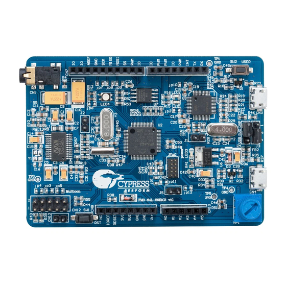
Introduction Inspect the contents of the kit; if you find any part missing, contact your nearest Cypress sales office for help: www.cypress.com/support. 1.2 Board Details Figure 1-2: FM0+ S6E1C-Series Starter Kit Markup Arduino Interface (CN7-CN10) Power supply resource select (J4) User button USB device connector (CN4) MB9AF312K programmer and debugger (CMSIS-DAP) - Page 6 Introduction Headphone and microphone jack (CN1) 15. Programming mode jumper (J2) 10. Reset button 16. Cypress FM0+ MCU S6E1C32D0A 11. Multicon connector (CN12, CN13) 17. RGB LED 12. Jumper for current measurement (J5) 18. NOR flash 13. 10-pin JTAG connector 19.
-
Page 7: Jumper And Connector
Introduction 1.3 Jumper and Connector Table 1-1: Jumper Description Jumper Function Setting Sets the programming mode pin (MD0) of Open: run mode MB9AF312K (CMSIS-DAP) Closed: serial programming mode Sets the programming mode pin (MD0) of Open: run mode S6E1C3 Closed: serial programming mode Serial programming mode Select for Pin 2 to Pin 1: UART programming mode (not supported on this S6E1C3... -
Page 8: Additional Learning Resources
Introduction 1.5 Additional Learning Resources Cypress provides a wealth of data at www.cypress.com to help you to select the right MCU device for your design, and to quickly and effectively integrate the device into your design. Visit the FM0+ product page for links to multiple resources, such as: ... -
Page 9: Installation And Test Operation
Installation and Test Operation This chapter describes the steps to install the software tools and drivers on a PC for using the FM0+ S6E1C-Series Starter Kit. After a successful installation, user can run the test code which is pre-programmed in the device. 2.1 Install Software Follow the steps below to install the FM0+ S6E1C-Series Starter Kit software: Download the FM0+ S6E1C-Series Starter Kit installer from the webpage:... - Page 10 Installation and Test Operation Click Install FM0-64L-S6E1C3 to start the kit installation, shown as Figure 2-1. Figure 2-1: Kit Installation Window Select the folder in which you want to install this package or use the default folder. When you click Next, the FM0+ S6E1C-Series Starter Kit installer automatically installs the required software, if it is not present on your PC.
- Page 11 Installation and Test Operation Choose the Typical, Custom, or Complete installation type (select ‘Typical’ if you do not know which one to select) in the Product Installation Overview window, as shown in Figure 2-2. Click Next after you select the installation type. Figure 2-2: Produce Installation Overview Read the License agreement and select I accept the terms in the license agreement to continue with installation.
-
Page 12: Un-Install Software
Installation and Test Operation 10. Click Install. Figure 2-3: Extract the Example Projects 11. Click Close to finish the extraction. After the installation is complete, the kit contents are available at the following location: Default location: Windows OS (64-bit): C:\Program Files (x86)\Cypress \FM0+ S6E1C-Series Starter Kit Windows OS (32-bit): C:\Program Files\Cypress \FM0+ S6E1C-Series Starter Kit... -
Page 13: Test Operation
Installation and Test Operation 2.3 Test Operation The FM0+ S6E1C-Series Starter Kit has been pre-programmed with a test demo code, which helps to test all of the on-board features. The Motorola-S format file, tp_fm0-64l-s6e1c3.srec, is provided in the following directory and can be programmed on the MCU by using the FLASH USB DIRECT Programmer. - Page 14 Installation and Test Operation Select the baud rate 115200, and click the Disconnected button to connect to the board. Figure 2-6: Select the Baud Rate Press the Enter key on your keyboard to run the test procedure. Key in the option number and press the Enter key to run the test.
- Page 15 Installation and Test Operation 2.3.2 Test Procedure Explanation This section explains the test procedure. This test procedure is based on the Serial Port Viewer. User has to key-in the test procedure number displayed on the menu and then press the Enter key.
- Page 16 Installation and Test Operation RGB LED Test: This procedure tests the RGB LED. Key in 2 and press the Enter key, the RGB LED color will change from red to green to blue. Figure 2-11: RGB LED Test SW2 Key Test: This procedure tests the switch SW2.
- Page 17 Installation and Test Operation NOR Flash Test: This procedure tests the NOR flash. Key in 5 and press the Enter key, the code will write a pre-determined set of data into the flash and then reads and compares to check whether the data is the same. If it is same, then it will display OK, otherwise it will display Fail.
-
Page 18: Hardware
Hardware This chapter describes the features and hardware details of the FM0+ S6E1C-Series Starter Kit. 3.1 System Block Diagram Figure 3-1 shows the system block diagram of the FM0+ S6E1C-Series Starter Kit. Figure 3-1: System Block Diagram 3.2 Hardware Features ... -
Page 19: Hardware Details
Hardware NOR flash memory Stereo codec RGB LED User button Arduino compatible headers Multicon interface 3.3 Hardware Details 3.3.1 FM0+Series MCU The S6E1C-Series Starter Kit features an ultra-low-power, highly integrated S6E1C3 MCU, a 32-bit ARM® Cortex®-M0+ MCU. The S6E1C3 MCU is a member of the S6E1C-Series device family with 40MHz CPU, 128KB flash, 16KB SRAM and 54 GPIOs. - Page 20 Hardware 3.3.3 Arduino Compatible Interface The FM0+ S6E1C-Series Starter Kit provides footprint compatibility with the Arduino interface. These headers expand the possibility for users to develop more applications based on this kit and different Arduino compatible shields. Figure 3-2 shows the pins. Figure 3-2: Pins of Arduino Compatible Interface FM0+ S6E1C-Series Starter Kit Guide, Doc.
- Page 21 Hardware Table 3-2 shows full definitions of the pins connected with the Arduino headers. Table 3-2: Pins of Arduino-Compatible Interface Pin No. Pin Name Arduino Designation Function (Part) UART – RX P33/ADTG_6/SIN6_1/INT04_0/MI2SDI6_1 UART – TX P32/SOT6_1/SI2CSDA6_1/TIOB2_1/INT05_2/MI2SDO6_1 P34/SCS61_1/TIOB4_1/MI2SMCK6_1 P3A/TIOA0_1/INT03_0/RTCCO_2/SUBOUT_2/IC1_CIN_0 P35/SCS62_1/TIOB5_1/INT08_1 P3B/TIOA1_1/IC1_DATA_0 P3C/TIOA2_1/IC1_RST_0 P43/ADTG_7/TIOA3_0 P02/WKUP5...
- Page 22 Hardware 3.3.4 Stereo Codec WM8731 is a low power stereo codec with an integrated headphone driver. On the digital side, it has an Inter-IC Sound (I2S) interface which is connected with the I2S macro. Table 3-3 explains the details of the signals. It also has an I2C interface for configuring the device and an I2S interface for audio data transmission.
- Page 23 Hardware 3.3.5 NOR Flash The S25FL132K non-volatile flash memory device connects to a host system via a Serial Peripheral Interface (SPI). The NOR Flash supports SPI single bit serial input and output (single I/O or SIO) as well as optional two bit (Dual I/O or DIO) and four bit (Quad I/O or QIO) serial protocols.
- Page 24 Hardware 3.3.6 Multicon interface The Multicon interface, CN12, is a 2x5 pin connector interface that brings the appropriate signals for UART, SPI, I2C and external interrupts. A simple 10-pin cable can be used to route the serial signals and power to a secondary board or another system. Pins 9 and 10 connect to an additional connector (CN13) to provide another connection point.
- Page 25 Hardware 3.3.7 Potentiometer The FM0+ S6E1C-Series Starter kit provides a potentiometer. Its resistance value ranges from 0 to 10k.The middle terminal is connected to the ADC channel AN00 (Pin40). Figure 3-6: Potentiometer 3.3.8 USB Interface The FM0+ S6E1C3 MCU has a USB channel that can work as a host or a device. In the FM0+ S6E1C-Series Starter Kit, the USB port is configured as a USB device and is connected to CN4, a micro USB type B connector.
- Page 26 Hardware 3.3.9 CMSIS-DAP The FM0+ S6E1C-Series Starter Kit features an on-board CMSIS-DAP module to enable programming and debugging of the FM0+ S6E1C3 MCU. The CMSIS-DAP firmware solution supports full JTAG configuration and two-wire Serial Wire Debug (SWD) interface. On this kit the CMSIS-DAP supports SWD only as the FM0+ S6E1C3 MCU has just the SWD interface.
- Page 27 Hardware 3.3.10 JTAG The FM0+ S6E1C-Series Starter Kit provides an interface, CN2, to connect an external programmer and debugger for programming and debugging the FM0+ S6E1C3 MCU. CN2 is a standard ARM 0.05’’ 10-pin Cortex debug header. Figure 3-9: 10-pin JTAG Interface 3.3.11 Multiplex Pins This board has some multiplexed pins.
- Page 28 Hardware 3.3.12 Jumpers for Current Measurement Wire jumpers jp11 and jp12 are used for connecting the 3V3 supply for FM0+ S6E1C3 MCU and peripherals respectively. The jumper J5 is in parallel with jp11. Figure 3-10: Power Supply Connection The power supply connection shown above enables customer to measure the current that FM0+ S6E1C3 MCU consumes.
-
Page 29: Software Development
Software Development 4.1 Tool Options The FM0+ S6E1C-Series device is supported by several third party tools/IDEs, and the user can choose his preferred tool for development. Any one of below listed IDEs can used for opening and building the example projects packaged with this kit: ... - Page 30 Software Development Click Project ->Rebuild All to build the project. Make sure the jumpers on the FM0+S6E1C-Series Starter board are placed according to the following table: Table 4-1: Debugging Jumper Setting Jumper Position Description Open Sets MB9AF312K (CMSIS-DAP) in run mode. Open Sets S6E1C3 in run mode.
- Page 31 Software Development 4.1.2 Open the Example Projects in Keil µVision IDE The following steps describe how to open, build and run an example project in Keil µVision IDE. Before proceeding, please check the availability of the flash loader file of the S6E1C3 device (S6E1C32X0.FLM) in this directory: <Keil_Install_Directory>:\ARM\flash.
-
Page 32: Example Projects
Software Development Make sure the jumpers on the FM0+S6E1C-Series Starter board are placed according to the Table 4-2. Table 4-2: Debugging Jumper Setting Jumper Position Description Open Sets MB9AF312K (CMSIS-DAP) in run mode. Open Sets S6E1C3 in run mode. Pin 1 to Pin 2 Power from USB port of CMSIS-DAP (CN3) Connect the USB cable to CN3 port. - Page 33 Software Development s6e1c3_bt_pwm Title: Base Timer Description: This project demonstrates the base timer operation of the S6E1C3 device. The project configures a base timer in PWM mode to generate a PWM sequence. The PWM output sequence from TIOA10_1 drives the green LED of LED4. The PWM duty cycle is updated every 2ms on another base timer, producing a breathing LED effect.
- Page 34 Software Development s6e1c3_sw_wdt Title: Software Watchdog Description: This project demonstrates the operation of the S6E1C3 watchdog by considering two different situations with the watchdog enabled: a) when the watchdog is fed and b) when the watchdog is not fed. If the watchdog is enabled and is fed in time, the program will run properly, and the RGB LED will blink green.
- Page 35 Software Development Run the Serial Port Viewer, set the baud rate as 115200, and click the Disconnected button to connect the board with PC, as described in Run the Test Demo. Figure 4-1: Select the Baud Rate Run the program and the ADC value will be displayed in Serial Port Viewer window. Figure 4-2: ADC value Turn the potentiometer (RP1), the ADC value will change.
- Page 36 Software Development 4.2.2.2 Hardware Connection No specific hardware connections are required for this project. All connections are hardwired on the board. 4.2.2.3 Verify Output Open the project in IAR Embedded Workbench Power the FM0+ S6E1C-Series Starter board from CN3 using USB cable, refer ...
- Page 37 Software Development Power the FM0+ S6E1C-Series Starter board from CN3 using USB cable, refer Figure 2-4. Open the project filein Keil uVision IDE from the following directory on your PC: <User_Directory>: FM0+ S6E1C-Series Starter Keil project: Kit_Ver01 \Firmware\Demo Projects\s6e1c3_dstc\ARM \s6e1c3_dstc.uvprojx.
- Page 38 Software Development 4.2.3 Flash Write 4.2.3.1 Project Description This project demonstrates the flash writing operation of the S6E1C3 device. A specific set of four values each of four bytes in size will be written into a specific address location in the flash memory.
- Page 39 Software Development Open the project file in Keil uVision IDE from the following directory on your PC: <User_Directory>: FM0+ S6E1C-Series Starter Keil project: Kit_Ver01 \Firmware\Demo Projects\s6e1c3_flash\ARM \s6e1c3_flash.uvprojx. Build the project and download the code to the S6E1C3 device. Open the Memory1 window from the View ->Memory Windows.
- Page 40 Software Development 4.2.4.3 Verify Output Power the FM0+ S6E1C-Series Starter board from CN3 using USB cable, refer to Figure 2-4. Open the project file in IAR Embedded Workbench or Keil uVision IDE from the following directory: IAR project: <User_Directory>: FM0+ S6E1C-Series Starter Kit_Ver01 \Firmware\Demo Projects\s6e1c3_mfs_uart\IAR \s6e1c3_mfs_uart.eww.
- Page 41 Software Development Key in any characters in the Outgoing Data Window, the same characters will be echoed in the Input Data Window. Figure 4-5: Echo Test 4.2.5 RTC Calendar 4.2.5.1 Project Description This project demonstrates the RTC operation of the S6E1C3 device. The program enables the RTC in calendar mode, and sends out the current calendar through UART0.The calendar starts from 2015/9/13 23:59:01 Wednesday.
- Page 42 Software Development Run the Serial Port Viewer, set the baud rate as 115200, and click the Disconnected button to connect the board with PC, as described in Run the Test Demo. Figure 4-6: Select the Baud Rate Run the program. The calendar data will be displayed in Serial Port Viewer window.
- Page 43 Software Development 4.2.6.3 Verify Output Power the FM0+ S6E1C-Series Starter board from CN3 using USB cable, refer to Figure 2-4. Open the project file in IAR Embedded Workbench or Keil µVision IDE from the following directory on your PC: IAR project: <User_Directory>: FM0+ S6E1C-Series Starter Kit_Ver01...
-
Page 44: Flash Programming
Software Development Run the program. The RGB LED (LED4) will blink with green color. Stop the program, comment out the line Swwdg_Feed(); in main.c file and click File ->Save. Exit from debug mode, then repeat the step 3~4. The RGB LED (LED4) will glow with green color. 4.3 Flash Programming 4.3.1 Programming the S6E1C3 Using FLASH USB DIRECT Programmer... - Page 45 Software Development Check the COM Port number in the Windows Device Manager. Enter the Virtual COM Port listed in the Ports of Device Manager in COM box. 10. Click the Full Operation (D+E+B+P) button to start programming. FM0+ S6E1C-Series Starter Kit Guide, Doc. # 002-10542 Rev. *D Arrow.com.
- Page 46 Software Development 11. Reset the S6E1C3 by pressing the reset button (SW1) on the board, and click OK. Note: Please click on Help for any issues or errors encountered during programming. 4.3.2 Programming CMSIS-DAP (MB9AF312K) Using FLASH USB DIRECT Programmer By default, the latest CMSIS-DAP firmware is programmed on the MB9AF312K already.
- Page 47 Software Development Check the COM Port number in the Windows Device Manager. Launch the FLASH USB DIRECT Programmer from Windows Start Menu > All Programs > Cypress > FLASH USB DIRECT Programmer > USBDirect Select “Target MCU” to MB9AF312K. Select the Motorola-S format file or Intel-HEX format file to be programmed to FLASH memory in the MCU.
- Page 48 Software Development 12. Reset the CMSIS-DAP microcontroller by removing and reconnecting the USB cable, and click OK. Note: Please click on Help for any issues or errors encountered during programming. 4.3.3 Programming the S6E1C3 Using the FLASH MCU Programmer The FLASH MCU Programmer is not supported on the S6E1C3 Starter Kit board. FM0+ S6E1C-Series Starter Kit Guide, Doc.
-
Page 49: Appendix
A. Appendix Schematic Figure A-1. MCU FM0+ S6E1C-Series Starter Kit Guide, Doc. # 002-10542 Rev. *D Arrow.com. Arrow.com. Arrow.com. Arrow.com. Arrow.com. Arrow.com. Arrow.com. Arrow.com. Arrow.com. Arrow.com. Arrow.com. Arrow.com. Arrow.com. Arrow.com. Arrow.com. Arrow.com. Arrow.com. Arrow.com. Arrow.com. Arrow.com. Arrow.com. Arrow.com. Arrow.com. Arrow.com. Arrow.com. - Page 50 Appendix Figure A-2. CMSIS-DAP & USB FM0+ S6E1C-Series Starter Kit Guide, Doc. # 002-10542 Rev. *D Arrow.com. Arrow.com. Arrow.com. Arrow.com. Arrow.com. Arrow.com. Arrow.com. Arrow.com. Arrow.com. Arrow.com. Arrow.com. Arrow.com. Arrow.com. Arrow.com. Arrow.com. Arrow.com. Arrow.com. Arrow.com. Arrow.com. Arrow.com. Arrow.com. Arrow.com. Arrow.com. Arrow.com. Arrow.com.
- Page 51 Appendix Figure A-3: Stereo Codec FM0+ S6E1C-Series Starter Kit Guide, Doc. # 002-10542 Rev. *D Arrow.com. Arrow.com. Arrow.com. Arrow.com. Arrow.com. Arrow.com. Arrow.com. Arrow.com. Arrow.com. Arrow.com. Arrow.com. Arrow.com. Arrow.com. Arrow.com. Arrow.com. Arrow.com. Arrow.com. Arrow.com. Arrow.com. Arrow.com. Arrow.com. Arrow.com. Arrow.com. Arrow.com. Arrow.com. Arrow.com.
- Page 52 Appendix Figure A-4: Interfaces FM0+ S6E1C-Series Starter Kit Guide, Doc. # 002-10542 Rev. *D Arrow.com. Arrow.com. Arrow.com. Arrow.com. Arrow.com. Arrow.com. Arrow.com. Arrow.com. Arrow.com. Arrow.com. Arrow.com. Arrow.com. Arrow.com. Arrow.com. Arrow.com. Arrow.com. Arrow.com. Arrow.com. Arrow.com. Arrow.com. Arrow.com. Arrow.com. Arrow.com. Arrow.com. Arrow.com. Arrow.com. Arrow.com.
-
Page 53: Bill Of Materials
Appendix Bill of Materials Item Reference Value Description Mfg part number C1, C3, C4, C7, C13, C17, C18, C19, C21, C22, C25, C28, C31, 0.1uF Capacitor without polarity YAGEO CC0603JRX7R9BB104 C32, C38, C41, C42, C43, C45, C46, C50 C2, C5, C6, C8, 10uF/6.3V Tan capacitor TAJA106K006RNJ... - Page 54 Appendix Item Reference Value Description Mfg part number 1225-1102ANGOS11.5 J1, J2, J5 2.54mm,2pins 2.54mm,2pins AIMO 1225-1103ANGOS11.5 J3, J4 2.54mm,3pin 2.54mm,3pins AIMO jp1, jp7, jp8, jp9, default open Wire jumper jp10 jp2, jp6 default closed Wire jumper jp3, jp4, jp5, jp11, default closed Wire jumper jp12...
- Page 55 Appendix Item Reference Value Description Mfg part number R23, R37, R40 Resistor YAGEO RC0603FR-071ML R39, R43 2.7k Resistor YAGEO RC0603FR-072K7L 4.7R Resistor YAGEO RC0603FR-074R7L R51, R54 510R Resistor YAGEO RC0603FR-07510RL 220R Resistor YAGEO RC0603FR-07220RL Resistor YAGEO RC0603FR-070RL 3386P-1-103T Potentiometer BURANS 3386P-1-103T 3.5*6*5mm, SMT, 2Pin SW1, SW2...
-
Page 56: Revision History
Revision History Document Revision History Document Title: FM0+ S6E1C-Series Starter Kit Guide Document Number: 002-10542 Origin of Revision Issue Date Description of Change Number Change 5062321 12/23/2015 CCTA Initial revision. 5151290 02/25/2016 CCTA 1. modify Figure 1-2, have an error for the #Item9 2.
Need help?
Do you have a question about the FM0+ S6E1C Series and is the answer not in the manual?
Questions and answers