Table of Contents
Advertisement
Quick Links
Advertisement
Table of Contents
Troubleshooting

Related Manuals for Benelli TNT125


Summary of Contents for Benelli TNT125
- Page 1 TNT125 Motorcycle Maintenance Manual...
- Page 2 Motorcycle Maintenance Manual All rights reserved! Without the prior written consent of dealer, no part of this Maintenance Manual may be reproduced, stored in a retrieval system or transmitted in any form (electronic form, mechanical copying, recording, etc.). We have made every effort to ensure that this Manual is complete and accurate, but will not assume any responsibility for any inaccuracies or omissions that may appear in this Manual.
- Page 3 Abbreviations Ampere Pound ABDC After bottom dead center Meter Alternating current Minute ATDC After top dead center Newton BBDC Before bottom dead center Pascal Bottom dead center Horsepower BTDC Before top dead center Pound per square inch Degree celsius Revolution ℃...
-
Page 4: Exhaust Emission Control Information
Exhaust Emission Control Information In order to protect our common environment, Zhejiang Qianjiang Motorcycle Co., Ltd. has introduced crankcase blow-by gas filtration system (1) and exhaust emission control system (2) which conform to the applicable regulations of the US Environmental Protection Agency and California Air Resources Board, and equipped the motorcycles sold in California only with fuel vapor recovery system (3) which conform to the applicable regulations of California Air Resources Board. - Page 5 Strictly Prohibiting the Modification of Noise Control System Federal law prohibit anyone from doing or instigating others to do the following: (1) Any person removes any part or make it inoperative before the final buyer purchases or receives any new motorcycle or in the course of the use of motorcycle, unless there is a need to repair, maintain or replace this part;...
-
Page 6: Table Of Contents
Contents Exhaust Emission Control Information ........................1 Strictly Prohibiting the Modification of Noise Control System ................2 Preface ..................................19 Chapter I Basic Information ..........................- 20 - Notes before Maintenance ........................... - 21 - Battery Grounding ..........................- 21 - Sharp Edge of Part .......................... - Page 7 Torque and Locking Agent .......................... - 48 - Main Locking Torque Specifications ....................- 48 - Nut, Bolt, Screw Fastening Torque and Relative Parameters .............. - 52 - Technical Parameters ........................... - 53 - Special Tools ..............................- 55 - Regular Maintenance Procedures ........................
- Page 8 Checking Accuracy of Headlight ....................- 87 - Checking Emergency Flameout Switch ..................- 88 - Others ..............................- 89 - Applying Lubricant to Frame Parts....................- 89 - Check Tightness of Bolt, Nut and Fastener ................. - 92 - Replacement Part ..........................
- Page 9 Fuel Leakage Check Process: ....................- 152 - Notes for Use: ............................ - 152 - Throttle Body ............................. - 154 - Working Principle of Throttle Body: ....................- 154 - Appearance of Throttle Body: ......................- 154 - Technical Parameters ......................... - 154 - Throttle Body: ..........................
- Page 10 Pin definition ............................. - 167 - Position .............................. - 167 - Cleaning ............................. - 167 - Fault Determination ........................... - 167 - Oxygen Sensor ............................- 168 - Working Principle of Oxygen Sensor ....................- 168 - Appearance of Oxygen Sensor ......................- 168 - Technical Parameters .........................
- Page 11 Fault phenomenon—Slight burning phenomenon ..............- 189 - Fault phenomenon—Fault lamp is on, but fault code is inconsistent with fault ......- 189 - Fault phenomenon—Extremely high fuel consumption ............- 190 - Fault diagnosis instructions for Delphi ....................- 191 - Chapter IV Engine .............................
- Page 12 The sound of piston is abnormal ....................- 225 - Special Tools ............................- 226 - Cylinder Block ........................... - 228 - Disassembling ..........................- 228 - Check ............................- 228 - Piston ..............................- 228 - Disassembling ..........................- 228 - Check ............................
- Page 13 Torque Valve ..........................- 253 - Cylinder Head Cover ......................... - 253 - Disassembling Cylinder Head Cover ..................- 253 - Checking Cylinder Head Cover ....................- 254 - Installing Cylinder Head Cover ....................- 254 - Kickstarter Component ..........................- 255 - Exploded View of Kickstarter Component ..................
- Page 14 Wheel / Tire ............................... - 281 - Exploded View of Front Wheel / Tire ....................- 281 - Technical Parameters ......................... - 284 - Special Tools ............................- 285 - Wheel (Rim) ............................- 286 - Disassembling Front Wheel ....................... - 286 - Installing Front Wheel .......................
- Page 15 Exploded View of Front Brake ......................- 309 - Exploded View of Rear Brake ......................- 311 - CBS of Hydraulic Brake ........................- 313 - Technical Parameters ......................... - 316 - Special Tools ............................- 317 - Brake Lever, Brake Pedal ........................- 318 - Checking the position of brake pedal ..................
- Page 16 Checking Brake Hose and Brake Pipe ..................- 337 - Suspension System ............................ - 338 - Exploded View of Front Suspension System ..................- 338 - Exploded View of Rear Suspension System ..................- 340 - Technical Parameters ......................... - 341 - Special Tools ............................
- Page 17 Exploded View of Seat Cushion and Guard..................- 384 - Exploded View of Engine ........................- 386 - Seat Cushion ............................- 388 - Disassembling Seat Cushion ...................... - 388 - Installing Seat Cushion ......................- 388 - Cowling ............................. - 389 - Disassembling Cowling ......................
- Page 18 Disassembling/Installing Engine ....................... - 407 - Exploded View of Engine Disassembly and Installation ............- 407 - Disassembling Engine........................ - 409 - Installing Engine ........................- 415 - Chapter VI Electrical System ..........................- 418 - Precautions ..............................- 421 - Technical Parameters ..........................
- Page 19 Checking Starter Motor ......................- 445 - Carbon Brush Inspection ......................- 446 - Commutator Cleaning and Inspection ..................- 446 - Carbon Brush Lead Inspection ....................- 447 - Right-hand End Cover Assembly Inspection ................- 447 - Starter Relay ............................- 448 - Disassembling Starter Relay ......................
- Page 20 Checking Fuse ........................... - 463 - Chapter VII Appendix ............................- 465 - Winding Method of Cable, Wire and Hose ....................- 467 - Main Cable ............................- 467 - Throttle Cable ............................ - 470 - Clutch Cable ............................- 471 - Oil Pipe ..............................
- Page 21 The drive system makes an unusual noise: ..................- 478 - Clutch noise: ..........................- 478 - Transmission device makes a noise: ..................- 479 - Drive system makes a noise: ...................... - 479 - The frame gives an unusual noise: ..................... - 479 - Front fork gives a noise: ......................
-
Page 22: Preface
“Remark”. devices required in the maintenance process of ★ This sign indicates the measures taken in Benelli motorcycle. For the original parts used as accordance with the test or check results in the spare parts, see List of Parts. -
Page 23: Chapter I Basic Information
Chapter I Basic Information Contents Notes before Maintenance ........................... - 21 - Battery Grounding ..........................- 21 - Sharp Edge of Part ..........................- 21 - Solvent ..............................- 21 - Cleaning Motorcycle before Disassembly ................... - 22 - Collecting and Cleaning Removed Part ....................- 22 - Storing Removed Part .......................... -
Page 24: Notes Before Maintenance
Notes before Maintenance Please read the following precautions before checking, disassembling or assembling motorcycles. In order to facilitate the actual operation, the chapters are provided with notes, illustrations, pictures, precautions and detailed descriptions. This section describes the special precautions during the removal and reassembly or disassembly and reassembly of common parts. -
Page 25: Cleaning Motorcycle Before Disassembly
Cleaning Motorcycle before Disassembly Thoroughly clean motorcycle before disassembly. If dust or other foreign matters enter the sealing area in the disassembly process, the excessive wear will be caused and the performance of motorcycles will be reduced. Collecting and Cleaning Removed Part The removed parts are easily confused. -
Page 26: Replacement Part
Replacement Part The replacement part must be an original part of Benelli or a part recommended by Benelli. Gaskets, O-ring seals, oil seals, grease seals, circlips or cotter pins and other parts must be replaced with new parts once they are removed. -
Page 27: Force
Force The common sense and basic ability of judgement must be owned in the part removal and installation process to prevent excessive force from resulting in maintenance difficulties or high maintenance cost. If necessary, remove the screws with threaded fastening glue by using a pneumatic wrench. - Page 28 Bearings, oil seals and other parts can be fit in place only by press-fitting, so a small amount of oil shall be applied on the contact parts. The parts must be aligned to the contact part during installation and then the parts can be slowly pressed.
-
Page 29: Ball Bearing And Needle Bearing
Ball Bearing and Needle Bearing If not necessary, do not remove the ball or needle in the bearing. Once the ball or needle is removed, it must be replaced with a new one. When pressing the bearing, note that the manufacturer and size signs shall be placed outward. -
Page 30: Circlip And Cotter Pin
Circlip and Cotter Pin Replace the removed circlip or cotter pin with a new one. In order to prevent deformation, the opening of circlip or cotter pin cannot be too large during installation. Lubrication In order to minimize the abrasion during running-in, the lubricant must be applied to the rotating parts or sliding parts. -
Page 31: Cable Connector Check
Cable Connector Check Make sure that there are no corrosion, moisture and other foreign matters on the connector. 1. Disconnection Wire Connector Joint 2. Check Wire Connector Joint If there are moisture traces, use the compressed air to dry it. -
Page 32: Check
4. Check Wire Connector Joint Note Make sure that all joints are assembled firmly. 5. Check Continuity (with multimeter) Note If there are no items to be checked, please wash the terminals. When checking the wire sheath, please carry out the operations in accordance with Steps 1 to 3 If you want to correct the operations rapidly, please use the [Contactor Reducer] sold in many spare... -
Page 33: Cable Arrangement
Cable Arrangement Loose cable is a potential electrical safety hazard. Check the latter cable after the cable is clamped to ensure the electrical safety; It is not allowed to bend the cable clamp in the direction of welding spot; Bind the cables at the specific position; It is not allowed to arrange the cables at the end of frame or at the position of sharp corner;... -
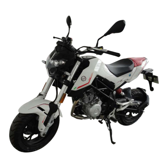
Page 34: Model Information
Model Information China Left view 31 -... - Page 35 Right view 32 -...
-
Page 36: Europe
Europe (European standard) Left view 33 -... - Page 37 (European standard) Right view 34 -...
-
Page 38: Non-Europe
Non-Europe (Non-European) Left view 35 -... - Page 39 (Non-European) Right view Frame No. Engine No.: China: *LBBPEJ3E?????????* BJ154FMI-7A*□□□□□□□□* Europe: *ZBNC02???????????* Non-Europe: *LBBPEJ3E?????????* 36 -...
- Page 40 Position of nameplate on frame Nameplate is riveted on the frame China Registered Benelli Vehicle trademark model: Two-wheeled motor vehicle Curb mass Displacem Engine model Zhejiang Qianjiang Motorcycle Co., Ltd. Manufactu (China) red in: Europe: Non-Europe: 37 -...
-
Page 41: Basic Specification
Basic Specification China Dimension Standard Overall length 1840mm Overall width 755mm Overall height 1025mm Wheel base 1215mm Enrope and Non-Europe: 38 -... - Page 42 Dimension Standard Overall length 1770mm Overall width 760mm Overall height 1025mm Wheel base 1215mm 39 -...
-
Page 43: General Technical Parameter
General Technical Parameter Item BJ125-3E China Enrope and Non-Europe: Dimension Overall length 1840mm 1770mm Overall width 755mm 760mm Overall height 1025mm 1025mm Wheel base 1215mm 1215mm Height above ground 160mm 160mm Height of seat 790mm 790mm Curb mass : 121kg Front wheel axle load 60kg Rear wheel axle load... - Page 44 General Technical Parameter Item BJ125-3E Oil : Type API SE, SFor SG API SH, SJ or SL(Including JASO MA, MA1or MA2) Viscosity SAE 10W-40 Capacity 1.1 L Driving mechanism Primary deceleration system: Type Gear Reduction ratio 3.750 Clutch type Wet multiple-piece type Transmission: Type 5-speed...
- Page 45 General Technical Parameter Item BJ125-3E Front suspension system: Type Inverted, extension-sleeve, oil damping absorber Total travel 125mm Rear suspension system: Type Single-cylinder, hydraulic spring, damping absorber Total travel 51mm Brake type: Front wheel Single disc φ220mm Rear wheel Single disc φ190mm Electrical equipment Battery 12V-6Ah...
-
Page 46: Unit Conversion Table
Unit Conversion Table Prefix of unit: Unit of length: Prefix Symbol Power km × 0.6214 = mile mega × 1 000 000 m × 3.281 = foot kilo × 1 000 mm × 0.03937 = inch centi ×0.01 milli ×0.001 Unit of torque: micro μ... -
Page 47: Chapter Ii Regular Maintenance
Chapter II Regular Maintenance Contents Regular Maintenance Table ......................... - 46 - Torque and Locking Agent .......................... - 48 - Main Locking Torque Specifications ....................- 48 - Nut, Bolt, Screw Fastening Torque and Relative Parameters .............. - 52 - Technical Parameters ........................... - Page 48 Checking Wear of Brake Pad ....................... - 76 - Checking Brake Light Switch ...................... - 76 - Suspension System ..........................- 77 - Checking Front Fork/Rear Shock Absorber ................. - 77 - Check for Oil Leakage of Front Fork Shock Absorber ..............- 77 - Check for Oil Leakage of Rear Shock Absorber ................
-
Page 49: Regular Maintenance Table
Regular Maintenance Table To keep good running state of motorcycle, regular maintenance must be conducted according to the following table. The maintenance for the first time is very important, so it should not be neglected. Regular Check Table ODOMETER READINGS 7000 KM 4000 KM 13000 KM... - Page 50 (Continued) ODOMETER READINGS 7000 KM 4000 KM 13000 KM 16000 KM 1000 KM 10000 KM ITEM ROUTINE or 15 or 3 or 6 or 9 or 12 months months months months months • Check chain slack, alignment and condition. • Adjust and lubricate chain with a special O- Drive chain Every 1000 km and after washing the vehicle or riding in the rain ring chain lubricant thoroughly.
-
Page 51: Torque And Locking Agent
Torque and Locking Agent Main Locking Torque Specifications The following table shows the locking torque of the main fasteners that are to be used with locking agent or silicone sealants. The letters in “Remark” column have the following meanings: AL: Tighten the mounting bolts alternately twice in accordance with the higher locking torque. G: Apply grease. - Page 52 (Continued) Torque Fastener Remark N·m kgf·m Crankshaft / drive mechanism Balancer shaft fastening nut M14 Mould closing bolt M6 Crankcase bolt Flywheel locking nut M25 10.0 Driving gear nutM20 Shifting and positioning plate bolt M6 Disassembly / installation of engine Front bracket bolt of engine (M10) Upper bracket bolt of engine (M8) Upper mounting bolt of engine (M10)
- Page 53 (Continued) Torque Fastener Remark N·m kgf·m Suspension system Front axle mounting bolt Front shock absorber mounting bolt (upper) Front shock absorber mounting bolt (lower) Front shock absorber top plug Front damper piston rod nut Rear shock absorber bolt (upper) Rear shock absorber bolt (lower) Rear shock absorber nut (lower) Rear swing arm shaft nut Steering system...
- Page 54 (Continued) Torque Fastener Remark N·m kgf·m Electrical system Alternator cover bolt Alternator wire fixing plate bolt Alternator Rotor Bolt 90-100 9.0-10.0 Camshaft position sensor bolt Camshaft sensor bolt 0.60 Camshaft sensor cover bolt L(1) Engine grounding terminal bolt Front brake light switch screw 0.12 Front steering light fixing nut Fuel level sensor bolt...
-
Page 55: Nut, Bolt, Screw Fastening Torque And Relative Parameters
Nut, Bolt, Screw Fastening Torque and Relative Parameters The following table shows the basic torques of bolt and nut (different thread diameters correspond to different tightening torques). This table is only applicable to the bolt and nut without the need for specific torque value. -
Page 56: Technical Parameters
Technical Parameters Item Standard Use limit Fuel injection system (EFI) Free clearance of throttle grip 3∼5mm ––– Idle speed 1500 ±100 r/min ––– Negative pressure value 34.4 ±1.3 kPa (under idle speed) ––– throttle body Air filter element Paper filter –––... - Page 57 (Continued) Item Standard Use Limit Brake Brake fluid: Level DOT4 ––– Thickness of brake lining Front brake lining 5.0 mm 3 mm Rear brake lining 6.8 mm 3 mm Brake light time setting: Front brake light It will be on after pulling the rope –––...
-
Page 58: Special Tools
Special Tools The following Special Tools are needed for complete and correct adjustment and assembly; use the correct Special Tools to avoid the damages caused by improper tools or non-professional technology. In different countries, the specific tools which need to be used may vary. During ordering tools, please refer to the following information to prevent any errors. -
Page 59: Regular Maintenance Procedures
Regular Maintenance Procedures Electronic Fuel Injection System (EFI) Checking Throttle Control System ●Check the free clearance of throttle grip [A]. Free Clearance of Throttle Grip Standard: 3-5mm ★If the free clearance is not accurate, please adjust the throttle cable. ● Check whether the throttle grip can move smoothly from fully open to closed and whether the return spring can enable the throttle to be turned off completely at any steering position. -
Page 60: Checking Idle Speed
★If the free clearance of throttle grip cannot be met by adjusting the upper end of throttle cable, adjust the lower end of throttle cable [B] and adjust the throttle cable according to the following steps: (1) Unscrew the lock nut [D]. (2) Rotate the adjusting nut [C] so that the free clearance of throttle grip [A] is large enough until the free clearance of throttle grip is 3-5mm. -
Page 61: Checking Fuel Hose (Fuel Leakage, Hose Break And Hose Installation Situations)
Checking Fuel Hose (Fuel Leakage, Hose Break and Hose Installation Situations) ○If the motorcycle is not handled properly, the high pressure inside the fuel pipe may lead to fuel leakage [A] or fuel pipe break. Remove the fuel tank (see “Fuel Tank Disassembly”... -
Page 62: Checking Fuel Evaporation And Recovery System (Chinese, European And Us Models)
Checking Fuel Evaporation and Recovery System (Chinese, European and US Models) ●Remove the canister according to the following steps. ○Remove the seat cushion (see “Seat Cushion Disassembly” in “Frame” chapter). ○Remove the left and right covers (see “Cover Disassembly” in “Frame” chapter). ○Remove fuel tank... - Page 63 ○Remove the bolt [A] and take the solenoid valve bracket of canister. ○Remove the hose used to connect separator and remove the canister solenoid valve [A] from the motorcycle. ○Check whether there are cracks or other damages on the canister solenoid valve. ★If any, it must be replaced.
-
Page 64: Engine Cylinder Head And Cylinder Head Cover
Engine Cylinder Head and Cylinder Head Cover Checking Valve Clearance Remark ○Valve clearance can be checked and adjusted only when the engine is cooled (to the indoor temperature). ●Disassemble: Remove the seat cushion (see “Disassembling Seat Cushion” in “Frame” chapter), Remove the fuel tank (see “Disassembling Fuel Tank”... - Page 65 ●Rotate the output sprocket to rotate the flywheel Timing mark on the assembly and align the timing mark on the flywheel observation hole assembly with the timing mark on the left cover observation hole. Output sprocket t Timing mark on the flywheel assembly ●After ensuring that the timing mark is aligned, put the...
-
Page 66: Adjusting Valve Clearance
●Use the thickness gauge to measure the valve clearance between rocker and valve lifter at the TDC position Note Please keep the thickness gauge level to prevent that the misjudgement gets stuck. ●Valve clearance Standard: Inlet valve: 0.05-0.07mm Exhaust valve: 0.05-0.07mm ★If the valve clearance is not within the specified scope, record the valve clearance and then carry out the adjustment. -
Page 67: Clutch
Clutch Checking Whether Clutch Control System is Normal ●Start the engine to ensure that the clutch cannot slip and can be separated normally. ★If the clutch is abnormal, check the clutch system. Warning If the motorcycle needs to be run in the checking process, ensure to run it at the place where the traffic conditions are normal. -
Page 68: Wheel/Tire
Wheel/Tire Checking Tire Pressure ●Remove the valve cap. ●Measure the tire pressure with an air pressure gauge [A] when the tire is cooled . ●Reinstall the valve cap back. ★If necessary, adjust the tire pressure according to the relevant specifications. Pressure (when the tire is cooled) Front wheel: 190±10 kPa Rear wheel: 210±10 kPa... -
Page 69: Checking Wear Situations Of Thread
Checking Wear Situations of Thread As the tread wear is more and more serious, it is more likely to cause tire blowout. It is estimated that 90% of tires will be damaged in the last 10% of service life of tire (90% wear). If the tire is used until it is grinded smoothly, the money cannot be saved and safety issues may be caused. - Page 70 check the wheel bearing (see “Disassembling Front Wheel and Checking Hub Bearing” in the “Wheel/Tire” chapter). ●Use the jack to lift the rear wheel up from the floor (see “Disassembling Rear Wheel” in the “Wheel/Tire” chapter) ●Shake the wheel frame to both sides [A] with both hands to check whether there is axial clearance in the rear wheel bearing.
-
Page 71: Final Drive Mechanism
Final Drive Mechanism Checking Lubrication State of Drive Chain ●If there is no special lubricant, the priority can be given to the heavy oil (e.g.: SAE 90), not light oil, because the heavy oil can be attached to the drive chain for longer time with better lubrication effect. -
Page 72: Adjusting Slackness Of Drive Chain
Adjusting Slackness of Drive Chain ●Lift the rear wheel up from the ground with a bracket (see “Disassembling Rear Wheel” in the “Wheel/Tire” chapter). ●Unscrew the rear wheel axle nut [A]. ●Screw the lock nuts [A] of two chain adjusters on the left and right out. -
Page 73: Checking Wheel Alignment
Checking Wheel Alignment ●Check whether the position of the concave scale line [B] on the right chain adjuster [A] on the rear swing arm [C] is the same as that of concave scale line on the left chain adjuster. ★If they are not aligned, adjust the slackness of drive chain and align the wheel alignment (see “Adjusting Slackness of Drive Chain”). -
Page 74: Checking Wear Of Chain Guide
Checking Wear of Chain Guide ●Remove the swing arm (see “Disassembling Rear Swing Arm” in “Suspension System”). ●Visually checking the chain guide [A]. ★If there is abnormal wear or damage in the chain guide, it must be replaced. 71 -... -
Page 75: Brake
Brake Check Whether Brake Hose and Brake Pipe are Damaged and Their Installation States ●Check whether the brake hose, brake pipe and accessories are corroded and whether there are cracks or leaks. ○If the brake hose and brake pipe are not properly maintained, the high pressure inside the brake pipe will cause the leakage of brake fluid [A] or rupture of brake hose and brake forming pipe. -
Page 76: Checking Brake
★If the measured result does not meet the specified valve, adjustment shall be carried out. ○Adjust the free travel of brake pedal. 1. Loosen the nut [B] on joint [A]. 2. Screw in or screw out the mandril [C] to adjust the free travel of brake pedal. - Page 77 ★If the level is lower than the lower limit, add the brake fluid in the reservoir until the level reaches the high fluid level line [A]. Remark ○Brake fluid may damage the painted surfaces or plastic parts. Therefore, wrap the absorbent paper around the pump and clear the spilled brake fluid immediately.
- Page 78 ●Install the cover of rear brake fluid reservoir correctly according to the following procedures. ○Tighten the cover [B] of rear brake fluid reservoir with hands clockwise [C] first until a slight resistance is felt, which indicates that the cover has been fixed to the reservoir, then hold the reservoir [A] and rotate another 1/6 turn [D].
-
Page 79: Checking Wear Of Brake Pad
Warning If the brake fluid needs to be added, but the type and brand of brake fluid in the brake fluid reservoir cannot be confirmed, all the brake fluid in the brake fluid pipe must be replaced. After replacing the brake fluid, only use the brake fluid of the same type and brand. -
Page 80: Suspension System
Suspension System Checking Front Fork/Rear Shock Absorber ●Shake the front fork up and down for four or five times to check whether the travel of shock absorber is smooth. ★If the front fork cannot be moved smoothly or there is noise, check the oil level or fork clamp of front fork shock absorber oil (see “Replacing Front Fork Shock Absorber Oil”... -
Page 81: Check For Oil Leakage Of Rear Shock Absorber
Check for Oil Leakage of Rear Shock Absorber ●Visually check for rear shock absorber [A] oil leakage. ★If oil leakage is found, replace the shock absorber. 78 -... -
Page 82: Steering System
Steering System Checking Steering Clearance ●。Lift the front wheel up from the ground with a jack. Special Tools—Jack: ●When the front wheel faces ahead straightly and the front wheel is lifted from the ground, the whole handle shall be able to slide freely to the left and right steering upper limits by the gravity action after the left or right handle is pushed slightly. - Page 83 Loosen the mounting bolt [A] of upper bracket [B] (Loosen) Remove the upper bracket [B] ●Remove the steering column lock nut [E]. Special Tools—steering column nut wrench: four jaws ●Adjust the steering column gland nut [F]. ★Tighten the steering column gland nut [F] to the torque of 30-35N·m Special Tools—steering column nut wrench: seven jaws...
-
Page 84: Applying Lubricant To Steering Column Bearing
(C): 30 N·m Tightening torque of handlebar mounting bolt (C): 22-34 N·m ●Check the steering gear again. ★If the steering gear is still too tight or loose, readjust ●Install the handlebar (see “Installing Handlebar” in the “Steering Gear” chapter). Applying Lubricant to Steering Column Bearing ●Remove the steering column (see “Disassembling Steering Column and Steering Column Bearing”... -
Page 85: Electrical System
Electrical System Checking Light and Switch Step 1 ●Open the electric door lock. ●All motorcycle lights will be on according to the order shown in the table below. Position light (LED) [A] High beam light (LED) [B] Low beam light (LED) [C] Front left turn signal light (LED) [D] Front right turn signal light (LED) [E] Taillight (LED) [F]... - Page 86 ●The indicator of meter will be on in the order shown in the table below. Tachometer light (LED) [J] Meter panel (LED) [K] Fault warning indicator (LED) [L] Indicator at neutral position (LED) [M] High beam light indicator (LED) [N] Turn signal light indicator (LED) [O] ★...
- Page 87 Step 2 ●Open the electric door lock. ●Turn on the turn signal switch [A] (left or right). ●Left turn signal or right turn signal (LED) (position of corresponding switch) (front and rear) will flash. ●Left/right turn signal light indicator (LED) [A] in the dashboard will flash.
- Page 88 System” chapter). ●Push the turn signal switch back. ●The turn signal light and turn signal light indicator (LED) shall dim. ★ If the lights do not dim, check or replace the following parts: Turn signal switch (see “Checking Switch” in the “Electrical System”...
- Page 89 ●The low beam headlights [A] and high beam headlight [B] shall be on. ● The high beam indicator (LED) [C] shall be on. If the high beam headlights and/or high beam light indicator (LED) are/is not on, check or replace the following parts: Headlights high beam bulb (see “Replacing Headlights Bulb”...
-
Page 90: Checking Accuracy Of Headlight
Checking Accuracy of Headlight ●Check the accuracy of headlights beam. ★If the headlight beam lights up one side instead of straight front, adjust the beam. Adjust the beam of front headlights correctly according to the following steps: Park the motorcycle about 10 meters away from the upright wall on the completely flat ground. -
Page 91: Checking Emergency Flameout Switch
Checking Emergency Flameout Switch Step 1 ●Open the electric door lock. ●Set the gear as neutral. ●Turn the emergency flameout switch to the stop position [A]. ●Press the starter button. ●At this time, the engine shall have not started. ★ If the engine has started, check or replace the following parts: Emergency flameout switch (see “Checking Switch”... -
Page 92: Others
Others Applying Lubricant to Frame Parts ●The rust must be removed with rust remover before any parts are lubricated and the grease, oil, stain or dirt shall be removed. ●Lubricate the following positions with the specified lubricant. Remark ○If the motorcycles are used in humid environment or on rainy days, especially when the motorcycles are sprayed and washed with high-pressure water, the relevant parts must be lubricated in... - Page 93 Clutch handle Pump connecting pin on rear brake Side stand 90 -...
- Page 94 Shift pedal Thread: apply grease Throttle cable steel cable end [A] Cable: apply antirust agent Throttle cable upper end ●Inject the antirust agent between cable and jacket to lubricate the cable. ○The sprinkling lubricant on the market can be bought and used for throttle cable steel cable 91 -...
-
Page 95: Check Tightness Of Bolt, Nut And Fastener
●After the connection between two ends of throttle cable steel cable, the steel cable shall be able to move freely [A]. ★If the steel cable cannot move smoothly after the lubricant is applied, the cable has been worn [B] or the throttle cable jacket is broken [C], the throttle cable must be replaced. - Page 96 Bolts, Nuts and Fasteners to Be Checked Engine: Bolt lock nut of clutch lever pivot, Mounting bolts and nuts of engine, Mounting bolts and nuts of hanging plate of engine, Branch holder nut of exhaust pipe, Clamp bolt of muffler, Mounting bolt of muffler cylinder I, Mounting bolt of muffler cylinder II;...
-
Page 97: Replacement Part
Replacement Part Replacing Air Filter Element Remark ○If the motorcycle is used in a dusty environment, the replacement interval of air filter element shall be shorter than the recommended replacement interval. ○After riding in rainy days or on muddy roads, replace the air filter element immediately. - Page 98 ●Install a new filter element [5]. Note The recommended air filter element (Benelli part number: 49202N220002) must be used. If other air filter elements are used, the engine will be worn prematurely or the performance of engine will be reduced.
-
Page 99: Replacing Fuel Pipe
Replacing Fuel Pipe ●Disassemble the fuel tank [see “Disassembling Fuel Tank” in the “Electronic Fuel Injection System (EFI)” chapter]. ●Pull out rubber cover of oil filter [A] from the fuel tank. ● Remove the fuel pipe from the fuel pump joint [A]. ●Make sure to enclose the hose joint [C] with a piece of cloth. - Page 100 ●When installing a new fuel pipe, fix the rubber cover of oil filter [A] on the fuel tank, as shown below. ● Arrange the fuel pipe correctly (see the section in the “Accessory” chapter: “Winding Method of Cable, Wire and Hose”). ●Insert the fuel pipe joint directly into the fuel supply pipe [A] until the hose joint clicks.
-
Page 101: Replacing Oil
Replacing oil ●After the engine becomes hot, place the motorcycle vertically and make it be perpendicular to the ground. ●Remove the oil drain bolt [A] to discharge the oil. ○Place an appropriate container under the oil drain bolt [A] to collect the oil. ●Drain: oil in the crankcase. - Page 102 Note Make sure that the oil level is between the oil lens Recommended oil Model: 10W/40SF Viscosity: SAE 10W-40 Capacity: 1.0 L 1.1 L (Engine is disassembled completely) Remark ○Do not add any chemical additives to the oil! The oil which meets the above requirements has been carefully prepared provide...
-
Page 103: Replacing Brake Hose And Brake Pipe
Replacing Brake Hose and Brake Pipe Note The brake fluid may quickly corrode the surfaces of painted parts, therefore, if the brake fluid splashes on any plastic part, it must be thoroughly rinsed immediately. ●Remove the hollow bolt [A] of brake hose. ●When the brake hose is removed, do not splash the brake fluid on any painted parts. - Page 104 ●Attention should be paid to the followings for the motorcycle model equipped with CBS: ●Remove the hollow bolt [A] of brake hose. ●When the brake hose is removed, do not splash the brake fluid on any painted parts. ●When the brake hose [B] is removed, temporarily fix the end of brake hose to a higher position to minimize the loss of brake fluid.
- Page 105 ●All sides of brake pipe accessory are equipped with gasket. The gasket shall be replaced with a new one during installation. ●Tightening: Locking torque of hollow bolt of brake hose: 30 N·m Locking torque of joint nut of brake pipe: 18 N·m (vehicle model equipped with CBS) ●When the brake hose is installed, avoid significant bending, kinking, extrusion or twisting and arrange it...
-
Page 106: Replacing Brake Fluid
Replacing brake fluid Warning Use only the prescribed brake fluid. Other types of brake fluid may damage the rubber seal, thus causing leakage and degrading the braking performance. Use the same brand of brake fluid in the process of adding brake fluid. Brake fluid must not be the mixture of different brands, because it may cause dangerous chemical reactions and also degrade braking performance. - Page 107 Replacing and filling rear brake fluid ●Disassemble: Reservoir cap [A], reservoir gasket. ●Loosen the bleed screw of slave pump of rear brake [B], and vacuumize from the bleed screw using a vacuum pump to pump the brake fluid completely. ●Add new brake fluid to master cylinder reservoir, keep the brake fluid in the reservoir not less than 1/3 of its volume, and pull the brake lever for several times quickly, and lock the bleed screw of slave cylinder [B].
- Page 108 Replacing and filling CBS pump brake fluid ●Disassemble: Reservoir [A] ●Disassemble: Reservoir cap and reservoir gasket Loosen the bleed screw of slave pump of front brake [B], and vacuumize from the bleed screw using a vacuum pump to pump the brake fluid completely. ●Add new brake fluid to master cylinder reservoir, keep the brake fluid in the reservoir not less than 1/3 of its volume, and pull the brake lever for several times...
- Page 109 cover. Locking torque of air drain screw: 7.8 N·m ●After the brake fluid is replaced, check whether the braking performance of brake is good, braking is blocked or brake fluid leaks. ★If necessary, blow out the air in the brake pipe. Warning The following precautions should be taken when handling disc brakes:...
-
Page 110: Replacing Rubber Parts Of Master Cylinder
Replacing Rubber Parts of Master Cylinder Disassembling Front Master Cylinder ●Remove front master cylinder (see “Disassembling Front Master cylinder” in the “Brake” chapter). ●Remove the sealing cover [4], spring [11], dust boot [12] and seal [8]. Special Tools—internal circlip plier: ●Screw out the lock nut [14]and pivot shaft bolt [5] and then remove the brake handle. - Page 111 Assembling Master Cylinder ●Before assembly, use the brake fluid or alcohol to clean all parts, including the master cylinder. Note Except for the brake pad and disc brake, other brake parts can only be cleaned by disc brake fluid, isopropyl alcohol or ethanol. Do not use any other fluid to clean above parts.
-
Page 112: Replacing Rubber Parts Of Calipers
Replacing Rubber Parts of Calipers Disassembling Front Calipers ●Before the front calipers are disassembled, drain the front brake oil. ●Loosen the front calipers fixing screw [A] and hollow bolt [B], and then gently unscrew them. ●Disassemble: Front calipers [C] (see “Disassembling Front Calipers” in the “Brake”... - Page 113 ●Remove the piston by using the compressed air. A piston removal method is shown below: ○Install a rubber gasket [A] and a wood board [B] with thickness of more than 10 mm (0.4 in.) in the middle of the calipers. Fix the rubber gasket and wood board together with appropriate bolts and nuts as shown in the figure.
- Page 114 CBS type 111 -...
- Page 115 Assembling Front Calipers ●Clean the calipers parts (except for the brake pad). Note The parts must be cleaned by using the disc brake fluid, isopropyl alcohol or ethanol! ●Replacing the new oil seal [A]. ○Apply the silicone grease to the oil seal, and then install it into the brake cylinder with hands.
- Page 116 CBS type ●Install the brake pad (see “Installing Front Brake Pad” in the “Brake” chapter). ●Wipe up the brake fluid which is splashed onto the calipers with a wet cloth. 113 -...
- Page 117 Disassembling Rear Calipers ●Remove the rear wheel (see “Disassembling Rear Wheel” in “Wheel / Tire” chapter) ● Separate calipers [A] and the brake disc. ●Loosen the hollow bolt [C] at the bottom of the brake hose. ●Remove the calipers mounting bolt [B], and remove the rear brake pad.
- Page 118 ●Disassemble: Dust seal [A], Oil seal [B], Remark ○If there is no compressed air, remove the piston from the two calipers according to the following method (the brake hose is connected with the calipers). ○Prepare a container to hold the brake fluid. ○Remove the brake pad spring and brake pad (see “Disassembling Rear Brake Pad”...
- Page 119 ●Apply the brake fluid to the outside of piston and press it into the brake cylinder with hands. ●Apply some thread fastening glue to the threads of rear calipers assembling bolts and then tighten the bolts. Locking torque of rear calipers assembling bolt: 37 N·m ●Install the brake pad (see “Installing Rear Brake Pad”...
-
Page 120: Replacing Spark Plug
Replacing Spark Plug ●Remove the ignition coil (see “Disassembling Ignition Coil” in the “Electrical System” chapter). ●Remove the spark plug [A] vertically with the wrench for spark plug. ●Replace them with two new spark plugs. Standard Spark Plug Model: A7RC (BOSCH) ●Insert a new spark plug into the spark plug hole and press the spark plug tightly with your finger. -
Page 121: Chapter Iii Electronic Fuel Injection System (Efi)
Chapter III Electronic Fuel Injection System (EFI) Contents Introduction to EFI ............................ - 122 - EFI System ..............................- 123 - EFI Part Position ............................- 125 - Technical Parameters ..........................- 131 - Fuel tank ..............................- 133 - Exploded View of Fuel Tank ...................... - Page 122 Fuel Leakage Check Process: ....................- 152 - Notes for Use: ............................ - 152 - Throttle Body ............................. - 154 - Working Principle of Throttle Body: ....................- 154 - Appearance of Throttle Body: ......................- 154 - Technical Parameters ......................... - 154 - Throttle Body: ..........................
- Page 123 Pin definition ............................. - 167 - Position .............................. - 167 - Cleaning ............................. - 167 - Fault Determination ........................... - 167 - Oxygen Sensor ............................- 168 - Working Principle of Oxygen Sensor ....................- 168 - Appearance of Oxygen Sensor ......................- 168 - Technical Parameters .........................
- Page 124 Fault phenomenon—Slight burning phenomenon ..............- 189 - Fault phenomenon—Fault lamp is on, but fault code is inconsistent with fault ......- 189 - Fault phenomenon—Extremely high fuel consumption ............- 190 - Fault diagnosis instructions for Delphi ....................- 191 - 121 -...
-
Page 125: Introduction To Efi
Introduction to EFI This motorcycle adopts the small engine EFI (electronic fuel injection) system Delphi Corporation. This system achieves closed-loop control, ECU fuel injection and ignition control through oxygen sensor. Three-way catalytic converter is used to handle the gas after the combustion of engine, to convert it into harmless gas and discharge it to the atmosphere. -
Page 126: Efi System
EFI System 123 -... - Page 127 Number of ECU connector Connector Function description (Black) (Grey) Idle speed control valve A J1-1 (high) J1-2 Canister solenoid valve J1-3 Fault light J1-4 J1-5 J1-6 Tachometer J1-7 CAN line signal (low) J1-8 CAN line signal (high) J1-9 Power (system) grounding J1-10 Idle speed control valve A J1-11...
-
Page 128: Efi Part Position
EFI Part Position 125 -... - Page 129 Throttle [A] Canister [B] Ignition coil [C] Battery [A] Fuse box [B] OBD joint Rectifier [A] 126 -...
- Page 130 ECU[A] Inlet air temperature pressure sensor [A] Oxygen sensor [A] Gear position sensor [A] 127 -...
- Page 131 Fuel injector [A] Meter [A] Power lock [B] Speedometer gear housing [A] 128 -...
- Page 132 Fuel level sensor [A] Fuel pump [A] Side stand Switch [A] 129 -...
- Page 133 Alternator [A] Trigger [B] Cylinder head temperature sensor [A] Idle speed stepper motor [A] Throttle openness sensor [B] 130 -...
-
Page 134: Technical Parameters
Technical Parameters Item Standard EFI system Idle speed 1500 ±100 r/min (rpm) Throttle assembly: Type Cylinder type Diameter Φ28 mm Negative value of throttle Bypass screw ––– ECU: MT05.2 Manufacturer Delphi Type Electronic memory type, equipped with IC ignitor, sealed using resin Avaliable engine rotation speed 100 - 15000 r/min (rpm) scope... - Page 135 (Continued) Item Standard Anti-theft device transceiver (model ≈0.6 ∼ 0.9 Ω equipped with anti-theft device transceiver) Resistance Oxygen sensor (model equipped with 6.7-10.5Ωat the temperature of 20°C (°F) oxygen sensor): Output power voltage (peak value when the air-fuel ratio is largest) Output power voltage (peak value when the air-fuel ratio is smallest) Heating coil resistance...
-
Page 136: Fuel Tank
Fuel tank Exploded View of Fuel Tank 133 -... - Page 137 Torque Name Remark N·m kgf·m Large-headed screw M6×25 Front mounting plate of seat cushion Protector bush Rubber cushion of protector Washer 6 Combination screw Rubber cushion of fuel sensor Oil level sensor components Fuel pump assembly Bolt M5×20 S、L Filter components Protective cover of filter Pipe components Fuel tank components...
-
Page 138: Evaporative Emission Recovery System Of Fuel
Evaporative Emission Recovery System of Fuel 135 -... -
Page 139: Disassembly Of Fuel Tank
Disassembly of Fuel Tank ●Disassemble front seat cushion (refer to “Frame”-“Disassembling Front Seat”) ● Disassemble fuel tank cover(refer to “Frame”-“Disassembling Fuel Tank Cover”) ●Disassemble rear mounting bolt of fuel tank [A] ●Disassemble front mounting bolt of fuel tank [A] ●Remove the connecting pipe [A] between fuel tank and check valve ●Disassemble the check valve [B] 136 -... - Page 140 ●Lift fuel tank, and unplug fuel pipe connected with throttle; Note: Note to prevent fuel oil from flowing out when unplugging the fuel pipe connected with throttle ●Place the fuel oil in the fuel tank in the container prepared. Warning: In the process of placing oil, keep away from open flame, to avoid fire ●Disassemble...
-
Page 141: Check
Check ●Check ○Whether there is rust inside the fuel tank ★Replace fuel tank in case of serious rust ●Check ○Dump valve ★Breakage/rust→Replacement ●Check ○Fuel pump ★Block→Cleaning ★Crack/damage→Replace the fuel pump assembly ○Check the performance of fuel pump (refer to: ) 138 -... - Page 142 ●Check ○Fuel level sensor ★Crack/damage→replace fuel level sensor ○Check the performance of fuel level sensor (refer to: “Electrical Devices” – “Oil Level Sensor”) ●Check ○Fuel hose ★If any wear, crack [B] or expansion [C] is found → the fuel pipe must be replaced. ●Check ○Ventilation hose ★If any wear, crack, gap or expansion is found →...
-
Page 143: Installatation Of Fuel Tank
Installatation of fuel tank ●Conduct installation in the reverse order of “disassembly” Note Do not damage the mounting surface of fuel tank when installing the fuel pump; Use new fuel pump seals; Use new fuel level sensor seals. Torque value: Oil level sensor tightening nut tightening torque: 6 N•m Fuel pump mounting bolt tightening torque: 4 N*m... -
Page 144: Notes For Efi Overhaul
Notes for EFI Overhaul Notes for EFI Overhaul There are many precautions for overhaul of EFI system. ○This EFI system must be powered by a 12V battery. Do not use any other battery as a power source for EFI system. ○Do not connect the wrong battery cable, or ECU may be damaged. - Page 145 ○When any fuel pipe is disconnected, the fuel will be discharged due to the residual pressure in the pipe. Therefore, it needs to cover the hose joint with a clean cloth to, so as to avoid spilling fuel oil. ○When installing the hose, avoid bending, kinking, squeezing or twisting the hose excessively.
-
Page 146: Ecu
Engine controller (MT05.2ECU) The engine controller can detect the running state of engine in real time through various kinds of sensors. Through reasonable calculation and self-learning control output device, it can ensure original vehicle emissions and fuel oil economy at the same time of optimizing the driveability of vehicles under different conditions. -
Page 147: Ecu Installation
ECU Installation ●Assemble it in reverse order of disassembly Tightening bolt torque of ECU: 3.9N·m Warning The installation surface must be flat, to prevent causing external stress to controller, which may result in bending of controller circuit board: Notes for ECU Notes Cause High temperature may reduce the service life of ECU... -
Page 148: Ecu Temperature Requirements
Reverse voltage: permanent damage will not caused to ECU after working for 1 minute at a reverse DC voltage of not exceeding 13 V. ECU Temperature Requirements Operating temperature: ECU can work normally at a ambient temperature of minus 20 degrees Celsius to 85 degrees Celsius. -
Page 149: Fuel Pump
Fuel pump Working of Fuel Pump Fuel pump assembly provides the gas to engine with 250Kpa gasoline pressure to meet system requirements. It is installed at the bottom of tank to provide the required fuel oil to engine through the connecting pipes. -
Page 150: Appearance Of Fuel Pump
Appearance of Fuel Pump 147 -... -
Page 151: Composition Of Fuel Pump
Composition of Fuel Pump 1. Pump harness 2. Pressure regulator 3. Fuel pump 4. Sealing washer 5. Fuel pump bracket 6. Fuel pump body Label and Mark of Fuel Pump Fuel pump assembly: make it at fuel pump assembly installing plate in the form of label. Fuel pump: make engraved mark at fuel pump. -
Page 152: Working Environment Of Fuel Pump
Working Environment of Fuel Pump The fuel pump assembly needs to be installed at the bottom of fuel tank according to the requirements. Fuel pump assembly design is generally only for gasoline fuel, ethanol and fuel with gasoline ratio of 22%. -
Page 153: Fault Diagnosis Of Fuel Pump Assembly
disassembling fuel line, in order to avoid the risk of occurrence, the blocking device at the fuel pipe should be used for blockage. After maintenance is completed, please ensure that the fuel line and clamp are properly installed. After maintenance is completed, check system oil ... -
Page 154: Installation Of Fuel Pump Assembly
Invert the fuel tank, be careful to avoid tank scratches and bumps. Remove fuel pump assembly installing bolt. Remove fuel pump assembly from the fuel tank carefully. Be careful to not damage fuel pump filter screen. Installation of Fuel Pump Assembly: ... -
Page 155: Fuel Leakage Check Process
each time. After completing the above operations, connect the fuel pump assembly harness connector. Fuel Leakage Check Process: After performing any fuel system maintenance, perform fuel leakage check test. Fill the tank with sufficient fuel. Turn on ignition key for 3 seconds, and then ... - Page 156 Ensure that there is no fuel leakage and seepage at pipe Please: use designated hose clamp joint Please: fix fuel pump harness at motorcycle Reduce shock The fuel with poor quality may damage the fuel pump Please: use standard fuel too early Please: replace fuel filter within the specified time Blocked filter may reduce fuel supply...
-
Page 157: Throttle Body
Throttle Body Working Principle of Throttle Body: Throttle body assembly mainly consists of the following components: main casting valve, bearing, shaft and valve plate, return spring, throttle wire part, throttle position sensing system, and bypass air volume control system. All of the above subsystems work together to meet the requirements for following functions: Intake flow control... -
Page 158: Throttle Body
Throttle Position Sensor: Reference voltage: 5±0.1VDC Resistance between T1 and T2: 3k-12kΩ Air Control Valve of Idle Speed: Working voltage: 7.5-14.2VDC Winding resistance: 53Ω±10% Winding inductance: 33mH±20% Working Environment of Throttle Normal working temperature: -30-120°C Disassembly of Throttle Turn off the power switch ... -
Page 159: Notes For Use Of Throttle
Always open the valve plate using throttle wire. Do not put tools or other items inside the throttle body to maintain the opening of valve plate. This may result in deformation of valve plate or scratching of inner wall of throttle body. Such damage may cause the valve plate to be too easily opened or difficultly. -
Page 160: Definition Of Pin
Definition of pin Dust cover Adjusting head (when it is at the maximum extension position, the adjusting head corresponds to , and it can move between 0.44 and 2.00 mm. Joint Complete retraction position Working position Characteristic parameter: Rated voltage: 12Vdc Maximum / minimum 7.5Vdc/14Vdc... -
Page 161: Circuit Inspection Of Idle Speed Stepper Motor
Standard: Air temperature: 20-30℃, 53±20%Ω Circuit inspection of idle speed stepper motor: Stepper motor Open circuit NG:A+ A-J1-01 Stepper motor Open circuit NG:A- B-J1-11 Stepper motor Open circuit NG:B+ C-J1-12 Stepper motor Open circuit NG:B- D-J1-13 Cleaning The stepper motor assembly is integrated at throttle body. -
Page 162: Fuel Injector
Fuel injector Additional resistor Various sensors Crankshaft position sensor Air flow meter Water temperature Micro sensor comp uter Throttle position sensor Ignition switch Oxygen sensor Vehicle speed sensor Storage battery voltage Working Principle of Fuel Injector Injector is an actuator. It can inject appropriate fuel into the intake of engine through ECU and then suck it into combustion chamber and then mix it with the oxygen in the fresh air filled for combustion. -
Page 163: Sealing Ring Of Fuel Injector
Sealing Ring of Fuel Injector As shown above, O-ring seal can ensure that leakage will not occur when fuel injector works within the range of -40°C -150°C (-40 -302°F), and it can resist various fuel additives (such as: ethyl alcohol). The following data is the existing sealing ring design. -
Page 164: Temperature Range Of Fuel Injector
will not affect the flow rate, cause permanent damage to the solenoid coil or weaken the electromagnetic performance. Temperature Range of Fuel Injector: The standard injector operating temperature range follows. Within qualified operating temperature range, the fuel injector flow is within the tolerance range and fault will not be caused. -
Page 165: Requirements For Installation Of Fuel Injector
Do not: store fuel injector, fuel rail or engine that has External environment may damage the electronic and been loaded into fuel injector in an unprotected mechanical parts of fuel injector. environment. Do not: take fuel injector as a handle when lifting assebly parts. -
Page 166: Replacement Method Of Fuel Injector
should not be reused. In the case of being resued in special conditions, please carefully check the sealing rings for damage. Very small damage may cause leakage. Carefully insert the sealing ring into the installing seat during installation. When installing the fuel injector connector, take care not to damage the connector, and you can hear a click, indicating that it is in place. -
Page 167: Fuel Injector Replaceability
check fuel injector for leakage. Start engine for running check. Fuel Injector Replaceability Only allow to replace the fuel injector with one with the same part number. Blocking of Fuel Injector The accumulation of fuel impurities may cause flow offset and shorten fuel injector life. When the engine is standing, the heat of engine may produce fuel precipitation through the head of fuel injector, and the precipitation gathered in the injection hole may cause... -
Page 168: General Failure Mode And Prevention And Solving Measures In Using Process
Warning: The injector is internally designed with a filter, Good but it is not a serviceable part because it is designed to filter out only the accumulated impurities between the fuel filter and the fuel injector in the fuel line, and these impurities may cause fuel injector bonding, flow offset and leakage and other faults, so the fuel filter is very important. -
Page 169: Intake Pressure Sensor
Intake Pressure Sensor Working Principle of Intake Pressure Sensor This sensor is used to measure the absolute pressure of air intake elbow, reflect the size of intake pressure according to the difference of resistance, and then calculate the intake volume in engine combustion chamber through indirect conversion, and it is also a non-serviceable part. -
Page 170: Pin Definition
Pin definition See the right figure Position Intake pressure sensor is integrated at throttle body Cleaning If necessary, the sensor can be cleaned with isopropyl alcohol and then air dried. It should be soaked in isopropyl alcohol for not more than 1 minute, and sealing connector should be installed during cleaning to prevent cleaner from intruding into the inside of sensor. -
Page 171: Oxygen Sensor
Oxygen Sensor Working Principle of Oxygen Sensor Oxygen sensor can be used to detect the oxygen content in the waste gas of engine exhaust pipe for internal fuel closed loop control of ECU, thus maintaining engine combustion at the most reasonable state of air and fuel ratio (14.7). -
Page 172: Oxygen Sensor Pin Definition
Oxygen Sensor Pin Definition: Connector of oxygen sensor 1. Heating control grounding of oxygen sensor (OSH-) 2. Heating power supply of oxygen sensor 12V+ 3. Signal of oxygen sensor – (OS-) 4. Signal of oxygen sensor+ (OS+) Fault Determination 1. Conduct fault diagnosis with a diagnostic instrument and judge the fault type 2. -
Page 173: Characteristic Curve
Characteristic curve Oxygen sensor is at exhaust manifold. Please first pull up oxygen sensor plug-in, and then remove the oxygen sensor with 13# open spanner, and pay attention to not knot or clinch the harness. Requirements for Fuel Quality Pb≤0.005g/L ... -
Page 174: Temperature Sensor Of Engine Cylinder Head
Temperature Sensor of Engine Cylinder Head Working Principle of Temperature Sensor of Engine Cylinder Head The engine cylinder head temperature sensor is used in the air cooled engine to measure the temperature of engine cylinder head. Within the sensor temperature range, the resistance will change with the temperature engine temperature... -
Page 175: Fault Determination And Characteristic Of Output Resistance
than 1mA. Fault Determination and Characteristic of Output Resistance Fault performance: This will have a large impact on start-up, because the ECU cannot monitor the temperature of engine or achieve accurate fuel injection. General faults are caused by the looseness of connection plug-in or the falling of the pin on the plug-in. -
Page 176: Canister Solenoid Valve (Ecp)
Canister Solenoid Valve (ECP) Overview of Working Principles Canister solenoid valve controls the fuel vapor in the canister into engine intake system from canister, and make it burn in the engine. Thus, reduce fuel evaporation emission. Appearance The appearance of canister solenoid valve is shown in the right figure: ECP Pin The pins do not have positive and negative electrodes, and the connection method is as shown below:... -
Page 177: Technical Parameters
Charcoal canister port Intake manifold port Electrical port Solenoid switch is normally closed Technical Parameters Normal operating voltage: 8-16V VDC Operating temperature: -40-120°C Operating frequency: 16 Hz Maximum flow: 25-35L/min Flow curve is as shown below: Duty cycle (%) Installation Requirements Canister solenoid valve should be horizontally... -
Page 178: Ignition Coil
Ignition Coil Appearance of Ignition Coil See the right figure Fault Description: If spark plug do not ignite or intermittently ignites, engine cannot work If the ignition coil fails and thus the spark plug does not ignite, the ECU will turn off the injection of corresponding cylinder, ie, do no inject fuel. -
Page 179: Fault Maintenance Diagnosis Method Of Efi System
Fault Maintenance Diagnosis Method of EFI System Diagnosis Directly Using the Flashing Fault Lamp at Instrument Fault lamp [A] is located on the dashboard and has a mark below it. Under normal circumstances, open the key, the fault lamps will be on normally, indicating that the EFI system is a state with power supply, and it can work;... - Page 180 ● MT05 Fault Code Table Remark: All fault display functions of Delphi are listed in the fault code table. If this model does not have the corresponding function, please ignore it) System or DTC Description Related Calibration Component Number P0107 MAP Circuit Low Voltage or Open KsDGDM_MAP_ShortLow anifold Absolute...
- Page 181 P0037 O2S Heater 2 Circuit Low Voltage KsDGDM_O2_HeaterShortLow Heater 2 Vehicle Speed P0500 VSS No Signal KsDGDM_VSS_NoSignal Sensor Park Neutral P0850 Park Neutral Switch Error KsDGDM_ParkNeutralSwitch Switch Diag P0445 CCP short to high KsDGDM_CCP_CircuitShortHigh P0444 CCP short to low/open KsDGDM_CCP_CircuitShortLow Rollover Sensor P1500 Rollover Sensor malfunction/Triggered...
-
Page 182: Diagnosing Fault Using Diagnostic Apparatus
Diagnosing Fault Using Diagnostic Apparatus ●Diagnostic Apparatus ●Operation Method: a) Find the diagnose interface [A] at motorcycle; b) Connect connecting wire and diagnostic apparatus interface; c) Open the key for diagnosis 179 -... - Page 183 Warning XCM-PT100X diagnostic apparatus is a high-precision instrument, so it should be protected from shock and vibration; If the instrument cannot work properly or display stably after the first start-up, please unplug the power cord and try again. Please ensure that the connector is always ...
-
Page 184: Common Troubleshooting Methods Of Electronic Fuel Injection System
Common Troubleshooting Methods of Electronic Fuel Injection System Maintenance Tool a) Disassembly and assembly of electronic control system components - common automotive mechanical parts removal tool b) Electronic control system circuit and system electrical signal - digital multimeter (with buzzer) c) Electric control system fault diagnosis and engine working condition detection Electronic... -
Page 185: Engine Working Data Flow Displayed By Diagnostic Apparatus
Engine Working Data Flow Displayed by Diagnostic Apparatus Analyze and determine engine fault using the engine working data flow displayed by the diagnostic apparatus. Step I a) Engine harness and the vacuum pipeline—may affect the system to control air flow and fuel supply b) Whether oxygen sensor is assembled in place—may affect the system to determine the air to fuel ratio c) Engine fault indicator—may affect the system to... - Page 186 Valve clearance is too large: it may cause low intake manifold pressure, and thus affect the system to determine the working state of engine, thus resulting in abnormal idle speed during warm-up of motorcycle. In addition, if the exhaust system is blocked, for example: a foreign body exists in the exhaust channel;...
-
Page 187: Simple Troubleshooting
Simple Troubleshooting Please follow the following steps to repair EFI system. To repair fault in one step, the subsequent steps may be stopped. And then use diagnostic apparatus to conduct inspection and acceptance and clear fault code according to section “Engine Working Data Flow Displayed by Diagnostic Apparatus”. -
Page 188: Fault Phenomenon-Start Fault
Fault phenomenon-Start fault Rotate ignition switch to “On” position, and check whether engine fault lamp is on. Check fuse and grounding wire If it is off: Check whether ECU plug is connected firmly It is able to check whether this lamp and line is normal using the check function of diagnostic apparatus actuator... - Page 189 work: working normally Check whether the connection and working of crankshaft position sensor is normal Use ECU for judgment Check fuel pump line 1) Check whether fuel supply pressure is able greater than 220Kpa 1) Check whether there 2) Insufficient work: is sufficient fuel in...
-
Page 190: Fault Phenomenon-Start Failure With Tempering
Fault phenomenon—Start failure with tempering a) Check whether ignition coil is loosened; b) Check whether timing gear ring is loosened. Fault phenomenon—Instable idle speed Idle Check whether the idle speed bypass control bolt is loosened system: Oil supply Check whether there is leakage in oil system: pipeline 187 -... -
Page 191: Fault Phenomenon-Too High Or Too Low Idle Speed
Fault phenomenon—Too high or too low idle speed (idle speed is obviously inconsistent with target idle speed) When the water temperature is high lower than 68 degrees, the system idle speed: will increase idle speed accelerate warming-up process, which is normal phenomenon. Check the items according to the following items except that ... -
Page 192: Fault Phenomenon-Instable Idle Speed With Deceleration And Flameout
Fault phenomenon—Instable idle speed with deceleration and flameout a) Checking valve clearance; b) Check whether idle speed bypass hole and throttle body are too dirt. Fault phenomenon—Insufficient power of deceleration a) Check whether the parameters are normal at idle speed and high idle speed; b) Check fuel quantity in the fuel tank and fuel filter;... -
Page 193: Fault Phenomenon-Extremely High Fuel Consumption
Fault phenomenon—Extremely high fuel consumption Check whether the oxygen sensors of two cylinders are assembled in place; if it is in the loose state, the oxygen sensor may incorrectly judge that the combustion in the cylinder is thin, and then increase fuel, which may result in unusually high fuel consumption. -
Page 194: Fault Diagnosis Instructions For Delphi
Fault diagnosis instructions for Delphi Requirements of latest regulations of the foruth phase of EU and China National IV Motorcycle: the motorcycle with electronic fuel injection system must be equipped with OBD2 fault diagnosis system, namely: When the motorcycle is started, the power fault light must be on. - Page 195 Sample of Diagnosis Table Name of rider: Registration number (license number): Year of first registration: Model: Engine No.: Frame No.: Date in the event of a fault: Environment in the event of a fault: □Clear □ Cloudy □Rain □Snow □Normal □Others: Weather □Very Cold □Normal □Others: □...
- Page 196 Chapter IV Engine Contents Main Parameters of Engine ........................- 197 - Lubrication System ............................ - 198 - Diagram of Lubrication System ......................- 198 - Position of Fuel pump ........................- 200 - Preparation Information ........................- 202 - Conventional Information ......................
- Page 197 Fault Diagnosis ..........................- 225 - Compression pressure is low ..................... - 225 - Compression pressure is high ....................- 225 - Exhaust pipe is emitting white smoke ..................- 225 - The sound of piston is abnormal ....................- 225 - Special Tools ............................
- Page 198 Subassembly of Cylinder Head Cover ....................... - 252 - Exploded View of Cylinder Head Cover ................... - 252 - Preparation Information ........................- 253 - Overview ............................- 253 - Technical Parameters ......................... - 253 - Torque Valve ..........................- 253 - Cylinder Head Cover .........................
- Page 199 Troubleshooting ..........................- 272 - Engine cannot start ........................- 272 - Starter Mechanism ..........................- 273 - Disassembling Starter Mechanism ..................... - 273 - Installing Starter Mechanism ..................... - 275 - 196 -...
-
Page 200: Main Parameters Of Engine
Main Parameters of Engine Main parameters of engine China European Standard Engine type Four stroke, single cylinder, four valves, double spark plugs Cooling method Air-cooled 54×58.8 Cylinder diameter stroke 54×54.5mm Displacement 134.6 ml 125ml Compression ratio Maximum net power / 9.3Kw/9000 r/min 8.2kw/9500rpm corresponding speed... -
Page 201: Lubrication System
Lubrication System Diagram of Lubrication System ① Rocker ② Rocker shaft ③ Camshaft ④ Crankshaft ⑤ Oil filter ⑥ Fuel pump ⑦ Primary oil filter 198 -... - Page 202 ①Camshaft ②Piston ③Oil jet ④Crankshaft ⑤Clutch 199 -...
-
Page 203: Position Of Fuel Pump
Position of Fuel pump 200 -... - Page 204 Expoloded drawing of fuel pump components 201 -...
-
Page 205: Preparation Information
Preparation Information Conventional Information Note If the used engine oil is stuck to the skin for a long time, skin cancer may be caused. Although it is unlikely the waste oil will be disposed of every day, wash the hands thoroughly with soap as soon as possible after disposing waste oil. -
Page 206: Technical Parameters
Technical Parameters Item Standard Use limit When replacing oil _ Oil capacity When disassembling 1.1L _ Radial clearance between internal 0.005-0.095 0.15 and external rotors Fuel pump rotor Clearance between external rotor 0.11-0.163 0.24 and pump body Clearance of end face of rotor 0.07-0.12 0.15 Torque Value... -
Page 207: Special Tools
Special Tools Oil pressure gauge Connector of oil pressuer gauge 204 -... -
Page 208: Troubleshooting
Troubleshooting Oil level is too low Oil consumption External leakage Piston ring is worn Improper installation of piston ring Cylinder body is worn Valve seal is worn Valve guide is worn Oil pressure is low Oil level is low ... -
Page 209: Checking Fuel Pump
Checking Fuel pump ●Remove the fuel pump base and disassemble fuel pump. ●Check the radial clearance of internal and external Test gauge rotors. ○Allowable limit: 0.15mm。 ●Check the clearance between external rotor and fuel Test gauge pump base. ○Allowable limit: 0.24mm。 ●Check the end clearance of rotor. -
Page 210: Cylinder Head / Distribution
Cylinder Head / Distribution Exploded View of Cylinder Head / Distribution 207 -... -
Page 211: Preparation Information
Preparation Information ●Function of Cylinder Head: Cylinder head is used to seal the cylinder and it forms a combustion chamber with the piston to withstand the high temperature and high pressure gas. And it can also complete the intake and exhaust through the valve mechanism. -
Page 212: Fault Diagnosis
Fault Diagnosis Compression pressure is low Valve clearance is not adjusted properly Valve burns out or is bent The airtightness of valve seat is not poor The gasket of cylinder head is leaking The spark plug is not installed properly The sound of cylinder head is abnormal Valve clearance is not adjusted properly Valve spring is damaged... -
Page 213: Special Tools
Special Tools Feeler gauge Callipers Micrometer Run-out gauge Valve spring compressor Valve reamer Spark plug socket wrench 210 -... -
Page 214: Cylinder Head
Cylinder Head Disassembling Cylinder Head ●Measure valve clearance with feeler gauge ○Standard of valve clearance: Intake valve clearance: 0.05-0.07mm Exhaust valve clearance: 0.05-0.07mm ★If there is a difference between the measured actual valve clearance and the standard valve clearance, the actual measured data can be compared with the standard clearance and the valve adjusting screw can be adjusted to achieve the standard valve clearance... - Page 215 ●Loosen the clamp bolts and remove tensioner components. ●Loosen the camshaft sprocket bolts. Remove the camshaft sprocket, chain, shaft end stop, shaft sleeve. ●Loosen the cylinder bolts and bolts at sprocket cavity side, and remove the oil deflector. 212 -...
- Page 216 ●Remove the cylinder head components. ●Remove the rocker shaft with M5 screws and remove the rocker. ●Measure the diemensions of rocker shaft using a micrometer. ○ Allowable limit of dimensions of rocker shaft: 7.94 ●Remove the spring with circlip pliers and remove the camshaft components.
-
Page 217: Checking Cylinder Head
●Measure the height of camshaft [a] with a micrometer. ○Allowable limit: Height of exhaust camshaft: 29.5376 Height of intake camshaft: 29.5426 mm ●Compress the valve spring with valve spring compression tool and remove valve cotter. ●Disassemble: Valve upper spring seat [1] Valve spring [2] Valve[3] Valve cottter [4]... - Page 218 ●Measure the free length of intake / exhaust spring of valve [a]. ○Allowable limit: Intake spring: 37.7mm. Exhaust spring: 37.7mm. ●Measure the gradient of intake / exhaust spring of valve [a]. ○Allowable limit: 1.6mm ●Measure the run-out of valve stem. ○Allowable limit: 0.04 mm ●Measure the outer diameter of valve stem.
-
Page 219: Replacing Valve Guide
●Check the valve guide and remove the carbon deposits in the valve guide with a reamer before check. Valve reamer Note Rotate the reamer clockwise and do not rotate the reamer counterclockwise. ●Allowable limit: Measure the inner diameter of valve guide [a]. - Page 220 ●Fix the cylinder head and remove the valve guide from the upper side of cylinder head with the valve guide disassembly tool [1]. ●Put a new O-ring on the new valve guide. ●Install the valve guide from the top of cylinder head. ○Install new valve guide using valve guide mounting tool [2] and guide using valve guide remover [1].
-
Page 221: Finishing Valve Seat Ring
●After the valve guide is embedded, carry out the finishing by using the valve guide reamer. Note Add an appropriate amount of cutting oil during cutting with a reamer. The reamer shall be rotated clockwise. ●Clean the carbon deposits in the combustion chamber and valve, and thoroughly rinse the intake and exhaust valves. - Page 222 ●Remove 1/4 of outer end of valve seat ring with a 25° cutter. ●Remove 1/4 of bottom of valve seat ring with a 60° cutter. Take the cutter and check the positions which have been disposed. ●Grind the valve seat ring with a 45° finishing cutter to reach an appropriate width.
- Page 223 ●Installation shall be carried out in the order contrary to the disassembly order. Precautions for Installation of Valve: ●When the valve is installed, apply appropriate amount of engine oil to the surface of the valve stem and then product install the valve stem into the valve guide. Valve spring retainer①...
-
Page 224: Cylinder Block / Piston
Cylinder Block / Piston Exploded View of Cylinder Block / Piston 221 -... -
Page 225: Exploded View Of Crankshaft
Exploded View of Crankshaft 222 -... -
Page 226: Preparation Information
Preparation Information ●Operation Precaution: All parts shall be cleaned and blown with high-pressure air before inspection and measurement. 223 -... -
Page 227: Technical Parameters
Technical Parameters Unit: mm Table of standard value and allowable limit of benchmark items Item Standard value Use limit Inner diameter 54~54.01 54.11 Cylindricity 0.005 0.05 Cylinder Roundness 0.004 0.05 Planeness 0.02 0.05 53.975~53.985 Outer diameter of piston (measurement (7mm at the bottom of piston 53.9 point) skirt) -
Page 228: Fault Diagnosis
Fault Diagnosis Compression pressure is low ●Wear, burning loss or damage of piston ●Wear or damage of cylinder and piston ●Damage of gasket and leakage between crankcase and gas Compression pressure is high ●Too many carbon deposition in the combustion chamber Exhaust pipe is emitting white smoke ●Wear and damage of piston ring ●Wear or damage of piston and cylinder... -
Page 229: Special Tools
Special Tools Feeler gauge Callipers Micrometer Run-out gauge Piston ring opening pliers Piston pin pulling-off device ① Opening pliers ② Piston 226 -... - Page 230 Cylinder diameter tester 227 -...
-
Page 231: Cylinder Block
Cylinder Block Disassembling ●Remove the cylinder block Cylinder block Check ●Check the wear situation of inner wall of cylinder. ★If the wear is serious, please replace it. ●Remove gasket and dowel pin. Gasket Dowel pin Piston Disassembling ●Remove the piston pin retainer. Note During disassembly, do not drop the retainer into the crankcase. -
Page 232: Check
●Remove the piston ring. ○Check the piston, piston pin and piston ring. Note: Do not break or damage the piston ring. ○Clear the carbon deposits inside the piston ring groove. Check ●Install the piston ring. Piston ○Measure the clearance between piston ring and piston ring groove. - Page 233 ●Measure the outer diameter of piston pin. ○Allowable limit: 13.96mm 。 Allowable limit: 13.96mm. ●Clearance between piston pin hole and piston pin. ○Allowable limit: 0.07mm. ●Measure the outer diameter of piston. Note The measurement position forms an angle of 90 degrees with the piston pin and it is 7mm below the piston skirt part.
-
Page 234: Installation
●Measure the roundness of inner wall of cylinder (inner diameter difference between X and Y directions). ○ Allowable limit: 0.05mm. Upper ●Measure the cylindricity of inner wall of cylinder (inner diameter difference between X and Y directions Middle in upper, middle and lower positions). ○Allowable limit: 0.05mm. -
Page 235: Installation Of Cylinder Block
○Scale the washers attached to the crankcase. “IN” mark Note Foreign matters shall not fall into the crankcase. ●Install the piston, piston pin and piston pin retainer. Note Install the piston into the intake valve according to the “IN” mark at the top. Installation of Cylinder Block ●Install the gasket and dowel pin on the crankcase. - Page 236 ●Measure the run-out of crankshaft. Measuring point ○Allowable limit: 0.1mm. ●Check whether the crankshaft bearing rotates with abnormal noise or whether it is loose. ★If there is abnormal noise or it is loose, replace the crankshaft assembly. Crankshaft bearing 233 -...
-
Page 237: Sub-Assembly Of Crankcase
Sub-assembly of Crankcase Exploded View of Crankcase 234 -... -
Page 238: Dismounting And Mounting Diagram Of Crankcase Bearing
Dismounting and Mounting Diagram of Crankcase Bearing Torque Chinese name and specifications Remark N·m kgf·m Oil seal Apply oil Needle bearing HK1010 Apply lubricating grease Rolling bearing 6203 Apply oil Needle bearing Apply lubricating grease Needle bearing HK1212B Apply lubricating grease Rolling bearing 6203 Apply oil Needle bearing... -
Page 239: Preparation Information
Preparation Information Overview The crankcase is a thin-wall casting and shall be protected against impact during operation to avoid deformation or damage. All parts should be rinsed and cleaned by using high-pressure air before inspection and measurement. The lubricant in the crankcase should be discharged before operation. -
Page 240: Crankcase
Crankcase Disassembling Crankcase ●Steps for opening crankcase: ○Components of right crankcase① a. Remove assembling bolt of crankcase Note: For the crankcase assembling bolt marked as shown in the figure, first loosen 1/4 of the engagement length and then completely loosen assembling bolt later in the staggered mode;... - Page 241 ●Check the crankshaft for defects such as cracks. ★If there is any defect, replace crankshaft components. ●Check the oil fitler for clogging and damage. ★If there is any defect, replace oil filter. ●Timing chain inspection ○Visually inspect the chain for wear, and feel whether the chain cannot rotate flexibly with two hands.
-
Page 242: Assembling Crankcase
●Crankcase bearing inspection ○Rotate the inner ring of bearing with your fingers to check whether the bearing cannot rotate flexibly and is blocked. ★If necessary, replace the new bearing with special tools. ●Oil seal inspection ○ Check the seal lip for damage or deformation, and whether there is any edge cut deformation in the outer ring. - Page 243 (7N•m). ●Clean the assembling surface and other joint surfaces. ●Apply sealant at the assembling surface: Note: Apply sealant around the bolt hole evenly, and prevent sealant going into the lubricating oil passage of crankcase. ●After the internal parts of left crankcase are assembled, assemble the right crankcase to left crankcase, and slightly knock the crankcase with a soft hammer;...
-
Page 244: Clutch
Clutch Exploded View of Left Cover 241 -... -
Page 245: Exploded View Of Clutch
Exploded View of Clutch 242 -... -
Page 246: Preparation Information
Preparation Information Conventional Information Install the engine on the frame, and disassemble right cover and clutch. Engine oil viscosity and oil level may affect clutch separation. When the clutch is not separated or unclear, check the engine oil level before repairing the clutch system. -
Page 247: Technical Parameters
Technical Parameters Item Standard Operating limit Free corner of clutch operating lever 10°-20° — Free length of clutch spring 35.5 34.2 Thickness of clutch friction 2.9-3.0 Wraping of clutch metal plate — Inner diameter of clutch bushing 17-17.018 17.028 Outer diameter of clutch bushing 22.967-22.98 22.957 Torque Value... -
Page 248: Special Tools
Special Tools Central pivot universal fixer of clutch 245 -... -
Page 249: Troubleshooting
Troubleshooting Clutch lever is too hard to pull ·The detaching mechanism of clutch is damaged ·The detaching bearing of clutch fails ·The push rod of clutch is not installed properly Clutch is slipping when accelerating ·The friction plate of clutch is worn ·The clutch spring is not elastic enough ·Engine oil is mixed with molybdenum or graphite additives Clutch does not disengage or clutch disengages suddenly during the running of motorcycle... -
Page 250: Right Cover
Right Cover Disassembing Right Cover ●Loosen the clamp bolt of foot lever and remove foot Foot lever lever. ●Loosen the clamp bolt and remove the right cover. Right cover Clamp bolt ● Remove the clutch push rod head and release bearing. Clutch cable ●... -
Page 251: Clutch
Clutch Disassembling Clutch ●Fix the clutch central pivot using a dedicated clutch Clutch spring mounting central pivot universal fixer, and loosen the clutch lock bolt nut. Clutch lock nut ● Remove the clutch lock nut and butterfly washer. Clutch ●Loosen the clutch spring mounting bolts and remove the clutch spring cover plate and clutch spring. -
Page 252: Assembling Clutch
●Remove the clutch external plate component. Clutch external plate component ●Remove clutch bushing and washer. Clutch bushing Washer Assembling Clutch ●Assemble the clutch in the reverse order of disassembly. 249 -... -
Page 253: Check
Check ●Check the outer groove of clutch for any burrs or broken marks. ★If necessary, finish it using a file, and replace it if the amount of finishing is too large. ● Check the tooth forms of clutch central pivot plate and retainer for damage. - Page 254 ●Check the flatness of clutch metal plate with a feeler gauge. ○Allowable limit: Replace it if its flatness is more than 0.3mm. 251 -...
-
Page 255: Subassembly Of Cylinder Head Cover
Subassembly of Cylinder Head Cover Exploded View of Cylinder Head Cover 252 -... -
Page 256: Preparation Information
Preparation Information Overview This section includes the services of cylinder head cover component, cylinder head cover gasket and bolts. When removing and storing parts, mark them to make sure they are reinstalled in their original positions. The disassembled parts need to be cleaned. When removing the cylinder head cover, be careful not to damage the matching cylinder head joint surface. -
Page 257: Checking Cylinder Head Cover
●Remove the gasket of cylinder head cover. Checking Cylinder Head Cover ●Check cylinder head cover ★If it is seriously worn, replace it. Installing Cylinder Head Cover ●Install the cylinder head cover in the reverse order of disassembly. ○When cylinder head cover is removed and reinstalled every time, the gasket of cylinder head cover must be replaced with a new one. -
Page 258: Kickstarter Component
Kickstarter Component Exploded View of Kickstarter Component 255 -... -
Page 259: Preparation Information
Preparation Information Overview This section includes the services of kickstarter lever component and kickstarter component. When removing and storing parts, mark them to make sure they are reinstalled in their original positions. The disassembled parts need to be cleaned. When disassembling the kickstarter component, be careful not to damage the matching 1st Gear of auxiliary shaft. -
Page 260: Installing Kickstarter Mechanism
●Remove the thrust washer, retainer 16, kickstarter spring, kickstarter ratchet, washer, retainer 13 and kickstarter gear component one by one. Installing Kickstarter Mechanism ●Install kickstarter mechanism in the reverse order of diassembly. ○Before assembly, all parts need to be cleaned, and oil should be added to gears and shafts. -
Page 261: Gearshift Mechanism
Gearshift Mechanism Exploded View of Gearshift Mechanism 258 -... -
Page 262: Technical Parameters
Technical Parameters Torque Value Start wheel bolt 12N•m Apply locking agent Positioning roller rocker bolt 12N•m Troubleshooting It is difficult to shift gears ·Clutch operation is incorrect · Oil viscosity is incorrect ·Shaft fork is bent ·Shaft fork shaft is bent ·Shaft fork jaw is bent ·... -
Page 263: Gearshift Mechanism
Gearshift Mechanism Disassembling gearshift mechanism ●Disassemble the following parts in order: ○ Positioning roller rocker bolt Positioning roller rocker bolt ○ Positioning roller rocker Positioning roller rocker ○ Rocker spring Rocker spring ●Disassemble Gearshift pin I ○Star wheel bolt ○Gearshift start wheel ○Gearshift pin I Star wheel bolt Gearshift start... -
Page 264: Checking Gearshift Mechanism
Checking Gearshift Mechanism ●Check the gear lever for bending, wear and damage ●Check if there is any damage to the spring of the shift lever and the elasticity is weakened. Replace if necessary. Gearshift spring Gearshift Installing Gearshift Mechanism ●Tighten the start wheel bolt after assembling Gearshift pin I gearshift start wheel. -
Page 265: Drive System
Drive System Exploded View of Drive System 262 -... -
Page 266: Technical Parameters
Technical Parameters Unit: mm Specifications Item Standard value Limit value Inner diameter 10.03 10~10.022 Shift fork Thickness of claw 4.9~5 4.87 Shift fork shaft Outer diameter 9.965~9.980 9.96 17.05 M4、M5 17.016~17.034 16~16.018 16.03 Inner diameter of gear 20~20.021 20.04 17.016~17.034 17.05 15.973~15.984 15.96... -
Page 267: Troubleshooting
Troubleshooting Drive system trips over stop or is out of gear ·Positioning roller rocker is damaged ·Positioning roller rocker spring is damaged or its elasticity is weakened ·Positioning roller rocker bolt is loosened ·Shift fork shaft or shift fork is bent or damaged ·Gearshift star wheel is bent or damaged ·Shift fork is bent or damaged The noise of engine is too large... -
Page 268: Primary Shaft Component
Primary Shaft Component Auxiliary Shaft Component 265 -... -
Page 269: Check
Check ●Check the shift fork (applicable to all shift forks) ○Shift fork head ① ○Shift fork claw ② ★Bending, damage, wear → Replace shift fork ●Check shift fork shaft ○Put the shift fork at a plane and roll it back and forth ★Bending →... - Page 270 ●Measure the runout of primary shaft (centering device and dial indicator are used) ★Exceeded limit dimensions → Replace primary shaft Limit dimensions of runout of primary shaft: 0.03mm ●Measure the runout of auxiliary shaft (centering device and dial indicator are used) ★...
-
Page 271: Installing Drive System
Installing Drive System Assembling Primary Shaft Component and Aauxiliary Shaft Component ●Install ○Spline washer ② ○Retainer ① Note: ○ Make sure that the sharp edge of retainer located on the opposite side from spline washer and the opening of retainer is located on the spline ○... -
Page 272: Installng Drive System
Installng Drive System ●Install ○Auxiliary shaft component ○Primary shaft component ○Shift drum component ○Shift fork of primary shaft ① ○Shift fork of auxiliary shaft ② ○Shift fork shaft ③ ○O ring seal Φ14×Φ1.8 ④ ○Oil seal bushing ⑤ ○Roller sprocket ○Mounting plate of drive sprocket ⑥... - Page 273 ●Check after installation ○Drive system ★It cannot rotate flexibly → repair Note: ·Fully apply oil to gears, shafts, bearings and other parts ·Make sure that the drive system is in a neutral state when assembling and that all gears can rotate flexibly 270 -...
-
Page 274: Starter Mechanism
Starter Mechanism Exploded View of Starter Mechanism 271 -... -
Page 275: Technical Parameters
Technical Parameters Specifications Item Stanard value Limit value Starter gear wheel Outer diameter of shaft section 49.1 49.175~49.2 Torque Value Left cover monting bolt 12N•m Left cover plate monting bolt 10N•m Flywheel lock nut 90-100N•m Stator component mounting bolt 10N•m Trigger head mounting bolt 7N•m Starter motor mounting bolt... -
Page 276: Starter Mechanism
Starter Mechanism Disassembling Starter Mechanism ●Loosen left cover bolt Left cover Note: Loosen the bolt in a criss-cross form, and loosen mounting bolt the bolt by 1/4 each time and then remove the left cover ●Remove starter gear wheel and idle gear components, Idle gear Starter gear wheel... - Page 277 ●Pull out the flywheel clutch using three-jaw chuck components Flywheel clutch component ●Loosen stator component mounting bolt and trigger Trigger head mounting head mounting bolt, and remove the stator component bolt Stator component Stator component mounting bolt 274 -...
-
Page 278: Installing Starter Mechanism
●Loosen the starter motor mounting bolt and take off Starter motor Starter motor the starter motor mounting bolt Installing Starter Mechanism ●Install starter mechanism in the reverse order of disassembly. 275 -... -
Page 279: Chapter V Finished Motorcycle
Chapter V Finished Motorcycle Contents Wheel / Tire ............................... - 281 - Exploded View of Front Wheel / Tire ....................- 281 - Technical Parameters ......................... - 284 - Special Tools ............................- 285 - Wheel (Rim) ............................- 286 - Disassembling Front Wheel ....................... - Page 280 Checking the Damper of Shaft Sleeve ..................- 308 - Checking the Wear of Sprocket ....................- 308 - Checking the Deformation of Rear Sprocket ................- 308 - Brake ................................- 309 - Exploded View of Front Brake ......................- 309 - Exploded View of Rear Brake ......................
- Page 281 Replacing Brake Fluid ....................... - 335 - Exhausting Air from Brake Pipe ....................- 335 - Brake Hose ............................- 337 - Disassembling / Installing Brake Hose and Brake Pipe ............. - 337 - Checking Brake Hose and Brake Pipe ..................- 337 - Suspension System ............................
- Page 282 Exploded View of Front Fender ......................- 376 - Exploded View of Rear Fender ......................- 378 - Exploded View of Cowling ........................ - 380 - Exploded View of Fuel Tank Guard ....................- 382 - Exploded View of Seat Cushion and Guard..................- 384 - Exploded View of Engine ........................
- Page 283 Installing Rear Right Pedal ......................- 403 - Muffler ............................... - 404 - Disassembling Muffler ......................- 404 - Installing Muffler ........................- 406 - Disassembling/Installing Engine ....................... - 407 - Exploded View of Engine Disassembly and Installation ............- 407 - Disassembling Engine........................
-
Page 284: Wheel / Tire
Wheel / Tire Exploded View of Front Wheel / Tire Torque Chinese name and specifications Remark N·m kgf·m Engine mounting shaft Gear housing component Rolling bearing 6301-2RS Front rim Vacuum tire 120/70-12 Intermediate sleeve of front wheel Oil seal component Right shaft sleeve of front wheel Front brake disc Hydraulic brake pad mounting bolt... - Page 285 Exploded View of Rear Wheel / Tire 282 -...
- Page 286 Torque Chinese name and specifications Remark N·m kgf·m Rear wheel axle Rear shock absorber mounting washer Rear wheel left shaft sleeve Self-locking nut M10×1.25 Sprocket Chain 428HG-1×116 Si R Dust ring component Rolling bearing 6204-2RS Chain drive axle sleeve Sprocket hub mounting washer Sprocket hub Sprocket mounting bolt Rear wheel damper...
-
Page 287: Technical Parameters
Technical Parameters Item Standard Use limit Wheel (rim) Rim oscillation: Axial ≤TIR 0.5 mm TIR 1.0 mm Radial ≤TIR 0.8 mm TIR 1.0 mm Wheel axle oscillation /100 mm ≤TIR 0.03 mm TIR 0.2 mm Wheel balancing ≤10 g ––– Balance weight 10 g, 20 g, 30 g –––... -
Page 288: Special Tools
Special Tools Complete set of tools for installing bearing Bearing remover shaft Jack: Jack accessories: Bearing remover head 285 -... -
Page 289: Wheel (Rim)
Wheel (Rim) Disassembling Front Wheel ●Disassemble: Front calipers mounting bolt [A] Front calipers [B] ●Loosen: Shaft tightening nut [A] (right side), Front shaft [A], ● Disassemble the fairing at the lower part (see “Frame”—“Disassembling Lower Fairing”). ● Lift the front wheel from the ground using a jack. Special Tools—jack and jack accessories: ●... -
Page 290: Installing Front Wheel
Installing Front Wheel Remark ○Rotating direction of wheel [A]. ●Check the rotation of front wheel, and then install front wheel. ●Press bearing [C] into the front rim. Remark ○First press the side of hydraulic brake disc. ●Apply high-temperature lubricating grease to the edge of the oil seal [D]. -
Page 291: Disassembling Rear Wheel
Disassembling Rear Wheel ●Lift rear wheel from the ground using bracket. ●Disassemble: Rear calipers mounting bolt [A], rear calipers [B] ●Loosen: Right chain adjuster [A], Chain adjuster locking nut [B], 288 -... - Page 292 ●Loosen: Left chain adjuster [A], Chain adjuster locking nut [B], ●Disassemble: Rear wheel axle nut [A], ●Disassemble: Rear wheel axle [A], ●Remove the drive chain of rear sprocket to the left ●Rotate rear wheel backwards to remove it. Note Do not place the wheel on the ground horizontally and make the brake disc towards, otherwise, brake disc may be damaged or deformed.
-
Page 293: Installing Rear Wheel
Installing Rear Wheel ●Apply high temperature grease to the edge of oil seal. ●Put shaft sleeve at two sides of hub. Shaft sleeve at right side [A] Shaft sleeve at left side [B] ●Install drive chain at the rear sprocket. ●Install calipers bracket [A] to the swing arm stop block [B]. -
Page 294: Checking Wheels
Checking Wheels ●Lift the front wheel / rear wheel from the ground. Special Tools: jack and jack accessories ●Gently rotate the wheel to check whether the wheels are able to rotate smoothly. ★If the wheels do not rotate smoothly, replace the hub bearings (see “Removing / Installing Wheel Bearings”). -
Page 295: Checking Dynamic Balance
Checking Dynamic Balance ●Disassemble front rear wheels (see “Disassembling Front / Rear Wheel”). ●Support the wheel so that the wheel can rotate smoothly. ● Rotate the wheel gently and make a mark [A] at the highest point when the wheel stops. ○... -
Page 296: Installing Grip End
20 g (0.71 oz.) 30 g (1.06 oz.) Remark ○ Benelli dealers sell the balance weights of 10, 20 and 30 g (0.35, 0.71 and 1.06 oz) respectively. The imbalance within 10g will not affect the driving stability of the motorcycle. -
Page 297: Checking / Adjusting Tire Pressure
●Push or knock [C] slot [D] and insert the grip end [A] onto the rib [B]. ○Mount the grip end to the left side of motorcycle. Left side [E] Right side [F] ●Check whether the balancer weight [A] and slot [B] are securely fixed on the rim [C] and slot is hung on the mounting base [D]. -
Page 298: Disassembling Tire
Disassembling Tire ●Disassemble: Tire (see “Disassembling Front Wheel / Rear Wheel), Air inlet valve (bleed) ●To keep tires balanced, make a mark at the place of air inlet valve stem using a chalk, so as to install the tires at the original places later Chalk mark or yellow mark [A], Air inlet valve [B], Aligning [C]... -
Page 299: Installing Tire
Installing Tire Warning Front and rear wheels must be the products of the same manufacturer! ●Check rims and tires and replace them if necessary. ●Clean the sealing surfaces of rims and tires, and make the sealing surface of rim smooth using a fine abrasive cloth if necessary. - Page 300 In view of this, Benelli does not recommend the use of temporary (external) maintenance, only recommend the use of reasonable permanent (internal) maintenance. The repair methods recommended by manufacturers may differ slightly.
-
Page 301: Hub Bearing
Hub Bearing Disassembling Hub Bearing ●Remove the wheel (see “Disassembling Front Wheel / Rear Wheel”), and remove the following parts: shaft shaft sleeve, shaft sleeve (removed from rear hub), oil seal ●Remove the hub bearing [A] with the bearing puller. Note Do not place the wheels horizontally on the floor and make the brake disc face down, or... -
Page 302: Checking Hub Bearing
Checking Hub Bearing Because the error of hub bearing is very small, generally it is unable to measure the clearance Remark ○Do not remove any bearing for check, because the bearing must be replaced with one after removal. ●If it needs to check whether there is an axial clearance in the bearing, it is jammed or blocked during the rotation, please rotate each bearing in the hub back and forth [A]! -
Page 303: Drive Mechanism
Drive Mechanism Exploded View of Drive Mechanism 300 -... - Page 304 Torque Chinese name and specifications Remark N·m kgf·m Rear wheel axle Rear shock absorber mounting washer Left bushing of rear wheel Self-locking nut M10×1.25 Sprocket Chain 428HG-1×116 Si R Dust seal component Rooling bearing 6204-2RS Chain drive axle sleeve Sprocket hub mounting washer Sprocket hub Sprocket mounting bolt Rear wheel damper...
-
Page 305: Technical Parameters
Technical Parameters Item Standard Lower use limit Drive chain Slackness of drive chain ––– 28 ∼ 35 mm Wearing capacity of drive chain 264.4 mm 254 ∼ 264.4 mm (with a length of 20 sections) Standard drive chain: Manufacturer ––– Model –––... -
Page 306: Special Tools
Special Tools Tools for disassembling and assembling chain: Complete set of tools for installing bearing: 303 -... -
Page 307: Drive Chain
Drive Chain Checking the Slackness of Drive Chain ●See “Regular Maintenance”—“Checking the Slackness of Drive Chain”. Checking the Slackness of Drive Chain ●See “Regular Maintenance”—“Adjusting the Slackness of Drive Chain”. Checking / Adjusting Wheel Alignment ●See “Regular Maintenance”—“Checking Wheel Alignment”. Checking the Wear of Drive Chain ●See “Regular Maintenance”—“Checking the Lubrication of Drive Chain”. -
Page 308: Installing Drive Chain
●Drive Chain: Main chain plate [A], Side plate of chain plate [C], Remark ○Insert the main chain plate from the inside of drive chain, and then assemble side plate, make ID sign towards the outside. Warning 。 Do not use old chain, main chain plate, side plate of main chain plate or rubber O-ring Installing Drive Chain ●Install:... -
Page 309: Sprocket, Shaft Sleeve, Shaft Sleeve Bearing
Sprocket, Shaft Sleeve, Shaft Sleeve Bearing Disassembling Rear Sprocket ●Disassembling rear wheel (see “Wheel / Tire”—“Disassembling Rear Wheel”). Note Do not place the wheel on the ground horizontally and make the brake disc towards, otherwise, brake disc may be damaged or deformed. -
Page 310: Disassembling Shaft Sleeve Bearing
Disassembling Shaft Sleeve Bearing ●Knock out the bearing [A] from one side of wheel. Special Tools—Complete Set of Tools for Installing Bearing: Installing Shaft Sleeve Bearing ●Replace one new bearing. ●Press bearing [A] towards the inside, until it reaches the top. Special Tools—Complete Set of Tools for Installing Bearing [B]: ●Apply high-temperature grease to the bearing. -
Page 311: Checking The Damper Of Shaft Sleeve
Checking the Damper of Shaft Sleeve ●Remove the shaft sleeve of rear wheel and check the rubber damper [A]. ●If the damper is damaged or corroded, please replace Checking the Wear of Sprocket ●Visually check the wear of engine and rear sprocket. ★If the wear of sprocket teeth is as shown in the figure, please replace the sprocket and check the wear of drive chain (see “Regular Maintenance”—“Checking... -
Page 312: Brake
Brake Exploded View of Front Brake 309 -... - Page 313 Torque Remark Chinese name and specifications N·m kgf·m Screw M6×23 Mounting cap Front brake switch component Washer φ4 Washer φ4 Screw M4×12 Bolt Lever Nut M6 Fuel pump component Hexagon flange bolts Seal Brake hose assembly Brake caliper (red) Friction plate component Inner hexagon screw M8×1.25×25 Front hydraulic brake component B: apply brake fluid.
-
Page 314: Exploded View Of Rear Brake
Exploded View of Rear Brake 311 -... - Page 315 Torque Chinese name and specifications Remark N·m kgf·m Rear hydraulic brake component Friction plate component Seal Hexagon bolt with flange Brake hose assembly Nut M6 Brake cylinder component (red) Plunger screw of foot pump Screw M8×20 Rear brake pressure switch Rear fuel pump component Bolt M6×12 B: apply brake fluid.
-
Page 316: Cbs Of Hydraulic Brake
CBS of Hydraulic Brake 313 -... - Page 317 Torque Chinese name and specifications Remark N·m kgf·m Screw M6×23 Mounting cover Front brake switch component Washer φ4 Washerφ4 Screw M4×12 Bolt Lever Nut M6 Fuel pump component Hexagon bolt with flange L, B Seal Front brake hose component Front right brake caliper component Friction plate component (front) Soket head cap screw M8×1.25×25 CBS linkage brake assembly...
- Page 318 CBS System (for motorcycle equipped with CBS) 315 -...
-
Page 319: Technical Parameters
Technical Parameters Item Standard Lower use limit Brake lever, brake pedal Brake lever position Not adjustable ––– Brake lever free clearance Not adjustable ––– Pedal free clearance Adjustable ––– Pedal position About 45 mm below the top of pedal ––– Brake pad Thickness of brake pad Front brake pad... -
Page 320: Special Tools
Special Tools Internal circlip plier: Multimeter: Jack: Jack accessories: 317 -... -
Page 321: Brake Lever, Brake Pedal
Brake Lever, Brake Pedal Checking the position of brake pedal ●Check whether the position of brake pedal [A] is correct. Footpeg [B] Pedal position Standard: About 45 mm below the top of footpeg ★ If the position of pedal is incorrect, adjust the position of brake pedal Adjusting the Position of Brake Pedal Remark... -
Page 322: Removing The Brake Pedal
Removing the Brake Pedal ●Disassemble: Right Front Pedal Bracket Bolt [B] Section Locking Screw [A] ●Disassemble: Brake pedal return spring [D] Eccentric push rod [B], Lower spring pin [C], •Disassemble the rear brake pedal installing screw [E], and remove the brake pedal [A]. Installing the Brake Pedal ●Install: Self-lubricating sleeve [C]. - Page 323 ●Install the right front pedal bracket. Locking Torque of Front Pedal Bracket Screw [A]: 40N•m •Install master cylinder fixing screw [B]. Locking Torque of Upper Rear Pump Fixing Screw [A]: 10N•m •Press the brake pedal [A], align the joint hole of the master cylinder, and install the fixing screw [B] and nut.
-
Page 324: Calipers
Calipers Disassembling Front Calipers ●Loosen the hollow bolt [C] at the bottom of the brake hose, and then tighten it slightly. ●Remove the calipers mounting bolt [B], and separate calipers [A] and the brake disc. Note Do not remove the calipers mounting bolts. To remove calipers, simply remove the calipers mounting bolt, because brake fluid may leak after removing calipers mounting bolt. -
Page 325: Disassembling Rear Calipers
Disassembling Rear Calipers ●Disassemble rear wheel (see “Disassembling Rear Wheel” in “Wheel / Tire”) ●Separate calipers [A] and the brake disc. ●Loosen the hollow bolt [C] at the bottom of the brake hose. ●Remove the calipers mounting bolt [B], and remove the rear brake pad Note Do not remove the calipers mounting bolts. -
Page 326: Installing Calipers
Installing Calipers ●Install the caliper and the lower end of brake hose. ○Replace the gaskets on both sides of the hose joint with new ones ●Locking torque: Locking Torque of Calipers Mounting bolt: Front calipers: 22 N•m Rear calipers: 22N•m Brake hose hollow bolt: 30N•m ●Check the fluid level in the brake fluid reservoir. -
Page 327: Checking Dust Seal Of The Calipers For Damage
Checking Dust Seal of the Calipers for Damage ●Check dust seal [B] for cracks, abrasion, expansion or other damages. ★If the dust seal is damaged, please replace it with a new one! Piston [C], Oil seal [A] 324 -... - Page 328 325 -...
-
Page 329: Checking The Calipers Piston And Brake Cylinder For Damage
Checking the Calipers Piston and Brake Cylinder for Damage ●Visually inspect the piston [A] and the brake cylinder surface [B]. ★ If the brake cylinder and piston are seriously worn or rusted, please replace the calipers! 326 -... -
Page 330: Brake Pad
Brake pad Disassembling Front Brake pad ●Disassemble front calipers ●Disassemble the fixed pin of brake pad[A]. ●Disassemble: Fixing pin of brake pad [A], When pulling out pin [A], please press safety spring ●Disassemble: Front brake pad [A] 327 -... -
Page 331: Installing Front Brake Pad
Installing Front Brake pad ●Push the calipers inward as far as possible. ●Install: The operations should be conducted in reverse order of disassembly. ●Check: brake fluid level [B], if it is lower than the minimum score, sufficient brake fluid recommended until it reaches the correct level. ●Check: brake handle operation, if the brake handle feels loose and soft, or light and soft, empty the air from the brake circuit. -
Page 332: Installing Rear Brake Pad
●Disassemble: Brake pad [A] Installing Rear Brake Pad ●Push the calipers inward as far as possible. ●Install: The operations should be conducted in reverse order of disassembly. ●Install calipers (see “Installing Calipers”) ●Check: brake fluid level [A], if it is lower than the minimum score, sufficient... -
Page 333: Installing Front Master Cylinder
●Disassemble the mounting bolt [A] between front brake hose and master cylinder. ●Disassemble: Brake handle pivot shaft bolt [B] and locking nut [C] Brake handle [A], front brake lamp switch fixing screw [B], flat washer [F] and spring washer [G] Front brake lamp switch [D] Front master cylinder [H] ●Disassemble front master pump... -
Page 334: Disassembling Rear Master Cylinder
Disassembling Rear Master Cylinder ●Disassemble: Rear master cylinder tightening bolts [A] Bolt [B] Rear brake lamp switch sensor [C], Rear master cylinder [D] •Slide out the clamp [A]. •Pull out the lower end of the oil reservoir hose [B] and drain the brake fluid into a container. -
Page 335: Disassembling Rear Master Cylinder
Locking Torque of Rear Master cylinder Mounting bolt: 25 N•m Locking Torque of Rear Brake Lamp Switch Sensor: 25 N•m ●Exhaust air from the brake pipe (see “Exhausting Air in the Brake Pipe”). ●Check whether the braking performance of the brakes is normal and the brake fluid leaks. Disassembling Front Master Cylinder ●See “Regular Maintenance”... -
Page 336: Brake Discs
Brake Discs Disassembling Brake Discs ●Disassemble wheels (see “Wheels Tires”—“Removing Front Wheels / Rear Wheels”). ●Disassemble mounting bolts and remove the brake disc. Installing Brake Disc ●Install the brake disc onto the wheels with the marked side facing out. ●Apply thread tightening glue to the threads of front brake disc and rear brake disc mounting bolts. -
Page 337: Checking The Deformation Of Brake Disc
Checking the Deformation of Brake Disc ●Lift the front wheel / rear wheel from the ground. ○In order to facilitate the inspection of the front brake disc, the handlebar can be completely inverted to one side. ●Turn the [B] wheel by hands and place the dial indicator on the brake disc [A] (see figure below) ), to measure the oscillation of brake disc. -
Page 338: Brake Fluid
Brake Fluid Checking the Level of Brake Fluid ●See “Regular Maintenance”—“Checking the Level of Brake Fluid”. Replacing Brake Fluid ●See “Regular Maintenance”—“Replacing Brake Fluid”. Exhausting Air from Brake Pipe Brake fluid compression coefficient is very small, so almost all the work of the brake lever or brake pedal will be transmitted directly to the calipers, thus generating braking effect. - Page 339 Warning The following precautions should be taken when handling disc brakes: 1. Do not reuse the brake fluid! 2. If the container containing of the brake fluid is not sealed or opened for a long time, do not use the brake fluid inside the container! 3.
-
Page 340: Brake Hose
Brake Hose Disassembling / Installing Brake Hose and Brake Pipe ●See “Regular Maintenance”—“Replacing Brake Hose and Brake Pipe”. Checking Brake Hose and Brake Pipe ●See “Regular Maintenance”—“Checking the Damage and Installation of Brake Hose and Brake Pipe”. 337 -... -
Page 341: Suspension System
Suspension System Exploded View of Front Suspension System 338 -... - Page 342 Chinese name and specification Torque Remark N·m kgf·m Inner hexagon screw M8×1.25×25 Upper seat of handlebar Lower handle positioned Damper Double end stud for positioning of handle Upper bracket clamp screw Upper bracket Handle positioning washer Self-locking nut M10×1.25 Upper bracket clamping nut Gland nut Dust seal Steering bearing...
-
Page 343: Exploded View Of Rear Suspension System
Exploded View of Rear Suspension System Chinese name and specification Torque Remark N·m kgf·m Swing arm axle Swing arm axle sleeve component G,R Middle shaft sleeve Self-locking nut M14×1.5 Bolt M6×10 Protective block Chain stop dog Bolt M6×19 Rear swing arm welding component Drive chain cover M6×15 Hexagon screw with boss M6×15... -
Page 344: Technical Parameters
Technical Parameters Item Standard Front shock absorber (each one) Diameter of front shock absorber φ35 mm inner pipe Pressure Pressure Atmospheric pressure (unadjustable) Front shock absorber oil: 22# shock absorber oil Viscosity 20 (at the temperature of 20℃) Oil quantity 315 ±2ml (after the disassembly, the oil has been drained completely) Free length of front shock absorber 245 mm (lower use limit: 80.9mm) (maximum deformation: 164.1) -
Page 345: Special Tools
Special Tools Internal calipers: Piston rod puller of front shock absorber Oil seal and bearing puller: Bearing puller shaft: Complete set of tools for mounting bearing: Bearing puller head: Jack: Jack accessories: Oil seal screwdriver of front shock absorber: Hook wrench: 342 -... -
Page 346: Front Shock Absorber
Front Shock Absorber Disassembling Front Shock Absorber ●Disassemble: Middle Fairings (see “Frame”—“Disassembling Middle Fairings”) Front wheel (see “Wheel/Tire”—“Disassembling Front Wheel”), Front fender (see “Frame”—“Disassembling Front Fender”) ●Disassemble the clamping bolt at the upper bracket of front shock absorber [A] ●Disassemble the clamping bolt at the lower bracket of front shock absorber [A] ●Turn the front shock absorber installing seat down to remove it. -
Page 347: Installing Front Shock Absorber
Installing Front Shock Absorber ●Keep the direction and position of top of outer pipe [A] as shown in the figure on the right before installing the front shock absorber. 1mm [B] ●Locking torque: Clamping bolt of front shock absorber (at the lower side): 22 N·m Clamping bolt of front shock absorber (at the upper side): 22 N·m... - Page 348 ●Install the fixing tool [A], as shown in the figure Remark ○The upper part protecting device [B] shall not touch the inner pipe when installing the fixing tool; pull up the outer pipe [C], clamp the outer pipe with the tool, and then lock the two bolts [D]. The outer pipe plays a guiding role.
- Page 349 ●Disassemble: Shock absorber spring [A] Spring seat [B] Adjusting sleeve[C] Damper and adjusting sleeve seat [D] ●Pour the shock absorber oil into a suitable container. ○Pull the piston rod up and down for at least ten times and pour out the shock absorber oil in the front shock absorber.
- Page 350 ●Rotate the shock absorber piston rod puller to the end of piston rod. Special Tool—Shock Absorber Piston Rod Puller: ●Pull the puller above the top of outer pipe. ●Installing: Adjusting sleeve, Damper and other parts Please replace with new parts! ●Fix the bolt at the top with a wrench and lock the piston rod nut [A].
-
Page 351: Disassembling Front Shock Absorber
Disassembling Front Shock Absorber ●Remove the front shock absorber (see “Disassembling Front Shock Absorber”). ●Discharge the shock absorber oil (see “Replacing Shock Absorber Oil”). ●Clamp the inner pipe of shock absorber with the tool. ●Disassemble Hexagon screw [C] Washer [B] Shock absorber mounting base [A] Locking torque of hexagon screw at the bottom of front shock absorber: 23 N·m... - Page 352 ●Separate the outer pipe [A] and inner pipe [B]. ●Disassemble Oil seal [A], Retainer ring [B], Dust seal [C] ●Replace the following parts with new ones: Oil seal [A], Retainer ring [B], Dust seal [C] ●Install the following parts on the inner pipe [A]. Dust seal [B], Retainer ring [C], Oil seal [D],...
-
Page 353: Checking Inner Pipe And Outer Pipe
Checking Inner Pipe and Outer Pipe ●Visually check the inner pipe [A] and replace it if there is any damage. ●If there are cracks or rust on the inner pipe, the sharp edge and tilted part can be worn with a millstone. The sharp edges or raised parts will damage the oil seal. -
Page 354: Rear Shock Absorber
Rear Shock Absorber Adjusting Spring Pre-tightening Force ●Remove the rear shock absorber from the frame (see “Disassembling Rear Shock Absorber”). ●Loosen the lock nut [B], rotate the adjusting nut [A] and loosen the spring. Special Tool—Hook Wrench: ●Adjust the spring pre-tightening force, rotate the adjusting nut [B] to the suitable position and tighten the lock nut [A]. -
Page 355: Disassembling Rear Shock Absorber
●In order to adjust the spring pre-tightening force, rotate the adjusting nut [A] to the suitable position and tighten the lock nut [B] with a hook wrench (the rear shock absorber is fixed on the frame). Special Tool—Hook Wrench ★If you feel that the spring is too soft or hard, please adjust Adjusting Spring Spring Dampin... -
Page 356: Installing Rear Shock Absorber
●Remove the rear shock absorber clamp bolt [A] at the lower side. ●Remove the shock absorber. Installing Rear Shock Absorber ●Locking torque: Clamp bolt above rear shock absorber: 50 N·m Clamp bolt below rear shock absorber: 50 N·m Checking Rear Shock Absorber ●Remove the rear shock absorber (see “Disassembling Rear Shock Absorber”). -
Page 357: Rear Swing Arm
Rear Swing Arm Disassembling Swing Arm ●Lift the rear wheel above the ground with a jack. Special Tool—Jack: Jack Accessories: ●Disassemble: Rear wheel (see “Wheel/Tire”—“Disassembling Rear Wheel”), ●Disassemble: Clamp bolt [A] at the lower side of rear shock absorber [B] (see “Disassembling Rear Shock Absorber”) ●Remove the swing arm installing shaft nut [A]. -
Page 358: Disassembling Swing Arm Bushing
●Put the installing shaft [A] into the frame from the left side. ●Lock the swing arm installing shaft nut [A]. Locking torque of swing arm installing shaft nut: 108 N·m ●Install it in reverse order of disassembly (see the corresponding chapters). Disassembling Swing Arm Bushing ●Disassemble: Rear swing arm (see “Disassembling Rear Swing... -
Page 359: Control System
Control System Exploded View of Control System 356 -... - Page 360 Torque Chinese name and specification Remark N·m kgf·m Internal hexagon screw M6x35 Counterbalance Counterbalance installing seat Right grip component Right combination switch Right rearview mirror component Throttle cable component Handlebar Left rearview mirror component Left combination switch Left handlebar grip Clutch handle component Clutch cable jacket Clutch cable component...
-
Page 361: Special Tools
Special Tools Outer ring shaft of head pipe : Steering pipe bearing installing tool (diameter: 42.5): Steering stem nut wrench: Mounting tooling adapter of steering stem bearing φ41.5: Complete set of tools used for mounting bearing: Outer ring screwdriver of head pipe: (diameter: 55): 358 -... -
Page 362: Control System
Control System Checking Control System ●See “Regular Maintenance”—“Checking Control System Clearance”. Adjusting Control System ●See “Regular Maintenance”—“Adjusting Control System Clearance” 359 -... -
Page 363: Steering Lever
Steering Lever Disassembling Steering Lever and Steering Lever Bearing ●Disassemble: Handlebar (see “Disassembling Handlebar”), Fairing (see “Frame”—“Disassembling Fairing”), Front wheel (see “Wheel/Tire”—“Disassembling Front Wheel”), Front fender (see “Frame”—“Disassembling Front Fender”), Front shock absorber (see “Suspension System”—“Disassembling Front Shock Absorber”), ●Disassemble: Upper bracket lock nut [A] Upper bracket [B], ●Remove the steering lever lock nut [A]. -
Page 364: Installing Steering Lever And Steering Lever Bearing
●To remove the ball bearing outer ring [A] which is pressed into the head pipe, insert a rod [C] into the inner cavity [D] of head pipe [B], and then knock both sides of ball bearing alternately to remove the outer ring. - Page 365 ●Replace the bearing inner ring and oil seal with new ones. ●Apply grease to oil seals. ●Cover the steering lever with oil seal [A], then install the ball bearing inner ring [B] at the lower side and apply grease to the steering lever. Special Tool—Special Tool for Steering Pipe Bearing Installation [D]: ●Install the ball bearing [A] at the lower side on the...
- Page 366 ●Install the bearing at the corresponding position according to the following method. ○Lock the steering lever nut with a locking torque of 55 N·m first and then loosen it for a small circle (less than one circle) to enable the nut to rotate slightly. And then lock it with a steering lever nut wrench [A] in accordance with the specified locking torque.
-
Page 367: Steering Lever Bearing Lubrication
●Install it in reverse order of disassembly (see the corresponding chapters). Steering Lever Bearing Lubrication ●See “Regular Maintenance”—“Steering Lever Bearing Lubrication”. Checking Deformation of Steering Lever ●If the steering lever is disassembled or the steering lever cannot be adjusted for smooth rotation, please check the straightness of steering lever! ★If the steering lever [A] is bent, please replace it! 364 -... -
Page 368: Handlebar
Handlebar Disassembling Handlebar ●Disassemble: Left rearview mirror [A] Clutch handle lock bolt [B] Clutch handle [C] Left combination switch [D] Handle counterbalance [E] Left handle grip [F] ●Disassemble: Right rearview mirror [A] Lock bolt of master cylinder of front hydraulic brake Master cylinder of front hydraulic brake [C] Right combination switch [D] Handle counterbalance [E]... -
Page 369: Installing Handlebar
Installing Handlebar ●Install the handlebar installing seat and handlebar on the upper bracket. ●Tighten the bolt of handlebar installing seat. Remark ○Lock the front handlebar installing seat bolt [A] and then lock the other one [B]. ○Lock two handlebar installing seat bolts twice alternately to ensure that the locking torque is even. - Page 370 ●Installing: Left handle [A] Left combination switch [C] ●Apply the thread fastening glue to the thread of handlebar counterbalance bolt and then tighten the bolt. ●Installing: Counterbalance [B] Left rearview mirror [D] Locking torque of combination switch fastening screw: 3.5 N·m 367 -...
-
Page 371: Frame
Frame Exploded View of Frame 368 -... - Page 372 Torque Chinese name and specification Remark N·m kgf·m Frame welding component Bolt M8×70 Bolt M10×1.25×90 Left front hanging plate of engine Right front hanging plate of engine Self-locking nut M8 AL、S Self-locking nut M10×1.25 AL、S Front guard mounting base Bolt M6×12 Bolt M10×1.25×110 Bolt M8×65 Upper hanging plate of engine...
-
Page 373: Exploded View Of Left Pedal
Exploded View of Left Pedal 370 -... - Page 374 Torque Chinese name and specification Remark N·m kgf·m Left front pedal bracket Left rear pedal bracket Bolt M8×1.25×30 Bolt M8×1.25×40 Bolt M8×1.25×35 Pedal mounting pin Left front pedal component Limiting spring Pedal ball Bushing Pedal limiting plate Retainer φ5 Pedal mounting pin Left rear pedal Pedal spring Pedal mounting plate...
-
Page 375: Exploded View Of Right Pedal
Exploded View of Right Pedal 372 -... - Page 376 Torque Chinese name and specification Remark N·m kgf·m Right front pedal bracket Right rear pedal bracket Bolt M8×1.25×30 Bolt M8×1.25×40 Bolt M6×20 Pedal mounting pin Right front pedal component Limiting spring Pedal ball Bushing Pedal limiting plate Retainer φ5 Inner hexagon screw M6×35 Rear brake pedal mounting screw Self-lubricating bushing Washer...
-
Page 377: Exploded View Of Muffler
Exploded View of Muffler 374 -... - Page 378 Torque Chinese name and specification Remark N·m kgf·m Exhaust pipe gasket component Oxygen sensor Graphite spacer Clamp Bolt M8×35 Master cylinder component II Slave cylinder component II Bolt M8×20 Spring gasket L: apply thread fastening glue. R: spare parts 375 -...
-
Page 379: Exploded View Of Front Fender
Exploded View of Front Fender 376 -... - Page 380 Torque Chinese name and specification Remark N·m kgf·m Front fender Left cowling cover of front fender Right cowling cover of front fender Stainless steel screw M6×15.2 Grey nylon gasket 6 Stainless steel screw M6×20 Speedometer cable clamp component Guard mounting bushing Hydraulic pipe clamp component Self-tapping screw ST4.2×13 Card ST4.2...
-
Page 381: Exploded View Of Rear Fender
Exploded View of Rear Fender 378 -... - Page 382 Torque Chinese name and specification Remark N·m kgf·m Rear fender Front of rear fender Screw M6×14 Card nut M6 Battery retainer component Mounting seat welding component of rear upper fender Screw M6×35 Washer 6 Spring washer 6 Rear upper fender collar Self-tapping screw ST4.2×13 Rear license plate mounting plate Rear license plate...
-
Page 383: Exploded View Of Cowling
Exploded View of Cowling 380 -... - Page 384 Torque Chinese name and specification Remark N·m kgf·m Cowling Cowling cover Self-tapping screw ST4.2×16 Sponge bar 1 Sponge bar 2 Left cowling mounting plate Right cowling mounting plate Inner guard of cowling Front left turn signal light Front right turn signal light Stainless steel screw M6×30 Guard collar Guard rubber washer...
-
Page 385: Exploded View Of Fuel Tank Guard
Exploded View of Fuel Tank Guard 382 -... - Page 386 Torque Chinese name and specification Remark N·m kgf·m Middle guard of fuel tank Screw M6×14 Fuel tank lock mounting plate Left guard of fuel tank Right guard of fuel tank Tapping screw ST4.2×10 Decorative screw M6×25 Gasket Rubber cover of front turn signal light bracket Card ST4.2 Self-tapping screw ST4.2×13 Left front guard of fuel tank...
-
Page 387: Exploded View Of Seat Cushion And Guard
Exploded View of Seat Cushion and Guard 384 -... - Page 388 Torque Chinese name and specification Remark N·m kgf·m Left guard Left guard Screw M6×14 Card nut M6 Left tail cover tail cover Right Connecting plate between left and right tail covers Decorative cover Self-tapping screw ST4.2×13 Decorative cover of left guard Decorative cover of right guard Self-tapping screw ST4.2×10 Left decorative plate...
-
Page 389: Exploded View Of Engine
Exploded View of Engine 386 -... - Page 390 Torque Chinese name and specification Remark N·m kgf·m Engine Fuel injector Injector clip Injector seat Intake air temperature sensor Inner hexagon screw M6×20 Throttle body assembly Bolt M6×25 Left rear cover assembly 387 -...
-
Page 391: Seat Cushion
Seat Cushion Disassembling Seat Cushion ●Insert the ignition switch key [A] into the seat cushion lock, turn the key counterclockwise, open the seat cushion [B] and lift up to remove the front seat cushion. ●Disassemble: Screw [A] Front seat cushion [B] Installing Seat Cushion ●Install it in reverse order of disassembly. -
Page 392: Cowling
Cowling Disassembling Cowling ●Disassemble: Screw [A] ●Disassemble: Screw [A] ●Pull out the joint of cable [A] 389 -... -
Page 393: Installing Cowling
●Take off the cowling, headlight and instrument combination. ●Disassemble: Front right turn signal light [A] Mounting plate of right cowling [B] Cowling cover[C] Cowling [D] Headlight[E] Instrument [F] Inner protective cover of cowling [G] Upper mounting plate of headlight [H] Mounting plate of left cowling [J] Front left turn signal light [K] Installing Cowling... -
Page 394: Guard
Guard Disassembling Left Guard ●Disassemble front seat cushion (see “Seat Cushion”—“Disassembling Front Seat Cushion”) ●Disassemble: Screw [A] ●Disassemble: Screw [A] Left guard [B] Installing Left Guard ●Install it in reverse order of disassembly. 391 -... -
Page 395: Disassembling Right Guard
Disassembling Right Guard ●Disassemble the front seat cushion (see “Seat Cushion”—“Disassembling Seat Cushion”) ●Disassemble: Screw [A] ●Disassemble: Screw [A] Right guard [B] Installing Right Guard ●Install it in reverse order of disassembly. 392 -... -
Page 396: Rear Tail Cover
Rear Tail Cover Disassembling Tail Cover ●Disassemble seat cushion (see “Seat Cushion”—“Disassembling Seat Cushion”) ●Disassemble left guard (see “Guard”—“Disassembling Left Guard”) ●Disassemble right guard (see “Guard”—“Disassembling Right Guard”) Disassemble: Screw [A] Right tail cover [B] Right turn signal light [C] Card nut [D] Connecting plate of left and right tail covers [E] Left tail cover [F]... -
Page 397: Rear Fender
Rear Fender Disassembling Rear Fender ●Disassemble the screw [A] and then remove the rear fender bracket from the frame ●Unplug the rear turn signal light and rear license plate cable [C] connector ●Disassemble: Screw [A] Self-tapping screw [B] Rear fender bracket [C] Rear license plate light [D] Rear license plate bracket [E] Rear fender [F]... -
Page 398: Front Fender
Front Fender Disassembling Front Fender ●Disassemble the screw [A] and remove the front fender from the front shock absorber ●Disassemble: Self-tapping screw [A] Card [B] Front fender [C] Left decorative cover of front fender [D] Right decorative cover of front fender [E] Installing Front Fender ●Install it in reverse order of disassembly. -
Page 399: Fuel Tank Guard And Fairing
Fuel Tank Guard and Fairing Disassembling Fuel Tank Guard ●Disassemble seat cushion (see “Seat Cushion”—“Disassembling Seat Cushion”) ●Disassemble fuel tank (see “Fuel Tank”—“Disassembling Fuel Tank”) ●Disassemble Middle guard of fuel tank [A] Left front guard of fuel tank [B] Left guard of fuel tank [C] Right guard of fuel tank [D] Right left guard of fuel tank [E] Connecting plate of left guard of fuel tank [F]... -
Page 400: Frame
Frame Disassembling Frame ●Disassemble: Seat cushion (see “Seat Cushion”—“Disassembling Seat Cushion”) Fuel tank (see “Fuel Tank”—“Disassembling Fuel Tank”) Guard (see “Guard”—“Disassembling Guard”) Tail cover (see “Tail Cover”— “Disassembling Tail Cover”) Rear fender (see “Rear Fender” — “Disassembling Rear Fender”) Rear wheel (see “Rear Wheel” — “Disassembling Rear Wheel”) Front wheel (see “Front Wheel”... -
Page 401: Side Stand
Side Stand Disassembling Side Stand ●Lift the rear wheel above the ground by using the bracket. ●Disassemble: Side stand spring [A] Nut [B], Side stand bolt [C] Side stand [D] Installing Side Stand ●Apply the grease to the moving part of side stand [D]. ●Apply the thread fastening glue to the thread of side stand bolt [C]. -
Page 402: Left Front Pedal
Left Front Pedal Disassembling Left Front Pedal ●Disassemble: Screw [A] Remove shift shaft rocker [B] ●Disassemble: Screw [A] Left front pedal bracket [B] ●Disassemble Left front pedal bracket [A] Left front pedal [B] Front pedal spring [C] Steel ball [D] Split retainer [E] Pedal installing plate [F] Pedal installing bushing [G]... -
Page 403: Installing Left Front Pedal
Installing Left Front Pedal ●Before installation, apply the grease to the pedal installing bushing. ●Install it in reverse order of disassembly. Locking torque: Mounting bolt of shift pedal component: 45 N·m Mounting scew of shift adjusting rod: 10 N·m Mounting scew of left front pedal bracket: 22N·m Mounting bolt of shift shaft rocker: 10 N·m 400 -... -
Page 404: Left Rear Pedal
Left Rear Pedal Disassembling Left Rear Pedal Disassemble: Screw [A] Left rear pedal bracket [B] ●Disassemble: Pedal mounting pin [A] Left rear pedal bracket [B] Left rear pedal [C] Pedal ball [D] Retainer [E] Pedal installing plate [J] Pedal Spring [G] Installing Left Rear Pedal ●Before installation, apply the grease to the pedal mounting pin. -
Page 405: Front Right Pedal
Front Right Pedal Disassembling Front Right Pedal ●Disassemble the right front pedal bracket (see “Brake”—“Disassembling Brake Pedal”) ●Disassemble: Pedal mounting pin [A] Right front pedal component [B] Right front pedal bracket [C] Pedal installing bushing [D] Pedal installing plate [E] Split retainer [F] Steel ball [G] Front pedal spring [D]... -
Page 406: Rear Right Pedal
Rear Right Pedal Disassembling Rear Right Pedal ●Disassemble: Screw [A] Right rear pedal bracket [B] ●Disassemble: Screw [A] Rear master pump [B] ●Disassemble: Pedal mounting pin [A] Right rear pedal [B] Right rear pedal bracket [C] Pedal ball [D] Retainer [E] Pedal mounting plate [F] Pedal spring [G] Installing Rear Right Pedal... -
Page 407: Muffler
Muffler Warning Do not disassemble the muffler when the engine is heated to avoid burn. Disassemble the muffler when it is cooled. Disassembling Muffler Loosen the mounting bolt [A] of clamp [B] ●Disassemble: Screw [A] Auxiliary cylinder component II of muffler [B] ●Disassemble: Oxygen sensor [A] 404 -... - Page 408 ●Disassemble: Holder nut of front exhaust pipe[A]. ●Disassemble: Screw [A] (two sides) Master cylinder component II [B] 405 -...
-
Page 409: Installing Muffler
Installing Muffler ●Replace the exhaust pipe washer [A] with a new one. ●Install it in reverse order of disassembly. Locking torque: Mounting nut of frong exhaust pipe: 22N·m Mounting bolt of master cylinder component II: 22 N·m Mounting bolt of auxiliary cylinder component II of muffler: 22 N·m Clamp fastening bolt: 22 N·m 406 -... -
Page 410: Disassembling/Installing Engine
Disassembling/Installing Engine Exploded View of Engine Disassembly and Installation 407 -... - Page 411 Torque Chinese name and specification Remark N·m kgf·m Frame welding component Upper hanging plate of engine Self-locking nut M8 Self-locking nut M10×1.25 Right front hanging plate of engine front hanging plate of engine Left Engine Bolt M8×70 S、M Bolt M10×1.25×90 S、M Bolt M10×1.25×110 S、M...
-
Page 412: Disassembling Engine
Disassembling Engine ●Support the rear part of swing arm with a bracket. ●Grasp the brake lever slowly and bind it with a tape. Warning The brake lever must be grasped when disassembling engine, otherwise motorcycle will topple, which will cause accidents and personal injury. - Page 413 ●Loosen the clamp [C] at the connection position of exhaust pipe of air filter [A] and throttle [B] Remove the oil-passing bolt [A] of oil cooling pipe [B] ●Disassemble Bolt [A] Shift rod rocker [B] 410 -...
- Page 414 ●Disconnect the connectors of cables [A] ●Support the engine using a suitable bracket and keep the engine balanced. ●Loosen: Mounting nuts at the engine and upper hanging plate Note: Do not remove the nut 411 -...
- Page 415 ●Loosen: Front mounting nut of engine [A] Note: Do not remove the nut ●Loosen: Mounting nut at front hanging plate of engine [A] Note: Do not remove the nut ●Loosen: Rear upper mounting nut at engine [A] Note: Do not remove the nut 412 -...
- Page 416 ●Loosen: Rear lower mounting nut at engine [A] Note: Do not remove the nut ●Remove: Mounting bolt at front hanging plate of engine [A] Front mounting bolt of engine [B] Front hanging plate of engine [C] ●Remove: Remove rear upper mounting bolt of engine [A] 413 -...
- Page 417 ●Remove: Remove rear lower mounting bolt of engine [A] ●Remove Mounting bolt at upper hanging plate of engine [A] Upper mounting bolt of engine [B] Mounting bolt at upper hanging plate of engine [C] ●利用架子取出发动机。Remove the engine by using the bracket. 414 -...
-
Page 418: Installing Engine
Installing Engine ●Support the engine with a suitable bracket. ●Install: Mounting bolt at upper hanging plate of engine [A] Upper hanging plate of engine [B] Nut [C] Note Do not tighten the nut [C]. ●Lift engine [C] ●Install: Uppe mounting bolt of engine [A] Nut [B] Engine [C] Note... - Page 419 416 -...
- Page 420 ●Fasten the bolt, screw or nut according to the following steps: ○Step 1: fasten the mounting bolt and nut of engine according to the right figure; ○Step 2: lock the mounting bolt and nut of front hanging plate of engine; ○Step 3: lock the mounting bolt and nut of upper hanging plate of engine;...
- Page 421 Chapter VI Electrical System Contents Precautions ..............................- 421 - Technical Parameters ..........................- 422 - Special Tools .............................. - 423 - Electrical Wiring ............................- 424 - Wiring Inspection ..........................- 424 - Charging System ............................- 425 - Circuit Diagram of Charging System ....................
- Page 422 Starter Motor ............................- 445 - Disassembling Starter Motor ..................... - 445 - Checking Starter Motor ......................- 445 - Carbon Brush Inspection ......................- 446 - Commutator Cleaning and Inspection ..................- 446 - Carbon Brush Lead Inspection ....................- 447 - Right-hand End Cover Assembly Inspection ................
- Page 423 Fuse ..............................- 463 - Disassmbling Fuse ........................- 463 - Installing Fuse ..........................- 463 - Checking Fuse ........................... - 463 - 420 -...
-
Page 424: Precautions
Precautions Many important precautions must be understood when maintaining the electrical system. Learn and follow all of the following rules. Do not reverse the positive and negative electrodes of storage battery, otherwise the diode of electrical component will be burned out. Check the battery state before checking other parts of electrical system. -
Page 425: Technical Parameters
Technical Parameters Item Standard Battery Type Maintenance-free storage battery Model YTX7L-BS Capacity 12 V 6 Ah Voltage Charging system Type Three-phase AC AC generator output voltage 5000 r/min 55V or above when it is 5000 r/min (rpm) Stator coil resistance 0.05-0.5Ω... -
Page 426: Special Tools
Special Tools Multimeter: Needle ammeter probe: 423 -... -
Page 427: Electrical Wiring
Electrical Wiring Wiring Inspection ●Visually check the melting, wear and other phenomena of wires. ★If the wire is broken, replace the damaged wire. ●Pull out each connector [A] to check corrosion, dirt and damage. ★If the connectors are corroded or soiled, carefully clean them. -
Page 428: Charging System
Charging System Circuit Diagram of Charging System 425 -... -
Page 429: Battery
Battery Disassembling Battery ●Close the power lock ●Disassemble seat cushion (see “Finished Motorcycle—Seat Cushion” chapter) ●Disassemble Upper cover of air filter [A] ●Remove the negative electrode of battery [A] * Note ○Make sure to disconnect the negative electrode (-) of cable ●Remove the positive electrode of battery [A] 426 -... -
Page 430: Battery Installation
●Remove the storage battery bracket [A] ●Remove the battery [B] from the battery fixing bracket Battery Installation ●Install the battery into the bracket ●Connect the negative (-) cable to the battery ●Apply a thin layer of grease on the terminal to prevent corrosion ●Connect the position (+) cable to the battery ●Cover the (+) terminal with a red cover [A]... - Page 431 Warning Do not tear the aluminum sealing fin [A] from the filling port [B] before use. Make sure to use the special electrolyte storage container to guarantee that the electrolyte of correct volume is filled ○Place the battery on the horizontal plane ○Check whether there are peeling, crack or hole on the sealing fin ○Disassemble the sealing strip...
-
Page 432: Initial Charge
Warning If the electrolyte in the electrolyte bottle is not injected into the storage battery completely, the service life of storage battery may be shortened. 20 minutes are needed when the electrolyte is injected into the storage battery completely, so do not remove the electrolyte bottle in advance. -
Page 433: Charging State Inspection
and load test if the voltage is less than 12.6V. If the voltage is still below 12.6V, the battery is defective. Charging State Inspection ●The battery can be checked by measuring the battery terminal voltage with a voltmeter [A]. ●Disassemble the battery ●Measure the battery terminal voltage *Note ○Use a digital voltmeter which can read a decimal... -
Page 434: Disassembling Magneto
Disassembling Magneto ●Magneto power wire connector ●Put a suitable container below the magneto cover ●Loosen the left cover mounting bolt [A] and remove the left cover [B] and coil ●Pull out the magneto power wire between the engine and bracket ●Disassembling stator coil: Magneto cover (see the magneto cover disassembly section) -
Page 435: Checking Magneto
Flywheel puller ●Remove the flywheel Checking Magneto ●There are three types of magneto faults: short circuit, open circuit (the wire is burned out) or magnetic loss of rotor. A short or open circuit of coil will result in low output or even no output. The magnetic loss of rotor will result in low output, this loss may be caused by the dropping or beating suffered by the AC generator, and it may also caused because the rotor is placed near the... - Page 436 K direction P direction White White Green / Blue / White white white ●Turn off the ignition switch ●Remove the 3P connector of magneto. ●Measure the impedance value among three black terminals of magneto with a multimeter. Standard value: 0.8±0.3Ω (normal temperature: 20℃) ★...
-
Page 437: Installing Magneto
○Record the voltage readings (3 measurement values in total) Table 1 Magneto Output Voltage Wiring Readings when it is Range of tester 5000rpm Connect tester (+) to Connect tester (-) to 750 V AC A black power wire The other black power wire 65V or higher ★If the displayed output voltage value is the value in the table, it indicates that the magneto runs normally. -
Page 438: Rectifier
Rectifier Disassebling rectifier: Disassemble right fuel tank guard (see “Frame” – “Disassembling Fuel Tank Guard” for details) ●Disassemble: Connector [A] Bolt [B] Voltage regulator/rectifier [C] Main Wiring Terminal Circuit Inspection Remove the motorcycle body guard. Remove the plug of voltage and current regulator and check the breakover among main wiring terminals in the following method. -
Page 439: Rectifier Installation
wire terminals of voltage stabilizer (white 1, white 2, white 3); the pointer table shows a certain value (range of 0.1-0.5V), otherwise it indicates that the voltage stabilizer is damaged and needs to be replaced. 3. Connect the red probe to the black wire terminal at the voltage stabilizer port and connect the black probe to the white wire terminals of voltage stabilizer (white 1, white 2, white 3);... -
Page 440: Ignition System
Ignition System Circuit Diagram of Ignition System Black/Red 1 黑/红1 Black/White 1 黑/白1 White blue 白 蓝 Green white 绿 白 Trigger probe 触发头 Ignition power Ignition system 点火电源 437 -... -
Page 441: Operation Precautions
Operation Precautions 1. Check the ignition system in accordance with the order of fault diagnosis table step by step. 2. The ignition system is the electronic automatic angle feeding device and has been cured in the ECU group, so the ignition time does not need to be adjusted. 3. -
Page 442: Crankshaft Sensor
Crankshaft Sensor Disassembling Crankshaft Position Sensor ●It cannot be disassembled separately and integrated with magneto (see “Charging System” – “Disassembling Magneto” for details) ●Crankshaft position sensor [A] Check ●Use the tester * Note The trigger can be checked on the engine. ●Remove the trigger lead connector. -
Page 443: Checking Ignition Coil
Checking Ignition Coil ●Check the primary coil ●Measure the impedance among the terminals of primary coil. Standard value: (0.58±10%)Ω(20℃) Coil resistance: Primary 0.58±10%Ω(20℃), Secondary 8±10%KΩ (20℃) High-pressure cap, internal resistance 5±10%KΩ ★The impedance value is good in the standard value. ★If the impedance value is “∞”, it indicates that the wire in the coil is disconnected and the ignition coil Ignition coil... -
Page 444: Check
Check ●Start the engine according to the following conditions First Check Condition: Drive device → 1st gear Clutch handle → hold Side stand → up ○Turn on the ignition switch and press the start button ○If the start-up system circuit is normal, the starter motor will not rotate ●If the engine starts, check the starting power-off switch, side stand flameout switch, gear switch and... -
Page 445: Ecu Group
electrical start-up safety circuit-related components operation checking section) Ignition system troubleshooting (see the ignition system section) 3. Electronic control unit voltage inspection (see the electronic control unit power inspection section in the chapter of electronic fuel injection system (ECU)) ECU Group ●System inspection ●Remove the ECU group and check the parts related to the ignition system at the wiring terminal. -
Page 446: Ignition System Troubleshooting
Ignition System Troubleshooting Error ignition (no spark) Battery inspection Not good Battery charging or battery replacement Good Ignition system circuit and connector Not good Repair or replace the damaged part inspection Good Spark plug inspection Not good Replace the spark plug Good Primary side coil peak voltage inspection Not good... -
Page 447: Starter System
Starter System Circuit Diagram of Starter System THE ON OFF SWITCH BATTERY RELAY FLAMEOUT SWITCH START SWITCH STARTOR MOTOR MAIN SWITCH 444 -... -
Page 448: Starter Motor
Starter Motor *Note Before the starter motor is disassembled, turn “OFF” the main switch, remove the bond strap of battery, and then turn on the power to see whether the motor runs to confirm safety. *Note Do not pat the starter motor shaft or body, otherwise the motor body may be damaged Disassembling Starter Motor ●Disassemble the starter motor cable terminal nut... -
Page 449: Carbon Brush Inspection
Carbon Brush Inspection ●Measure the length [A] of each carbon brush [B] ★If any carbon brush has reached the use limit, replace the carbon brush plate assembly Length of Starter Motor Carbon Brush Standard: 11.5 mm Use limit: 6.0mm Commutator Cleaning and Inspection ●If necessary, polish the surface [A] of commutator with a crocus cloth [B] and clear the groove ●Measure the diameter [A] of commutator [B]... -
Page 450: Carbon Brush Lead Inspection
Carbon Brush Lead Inspection ●Measure the resistance by using a multimeter with the range set as × 1Ω, as shown in the figure End bolt and positive carbon brush [A] Right-hand end cover and negative carbon brush ★★If the resistance is not close to zero ohms, the carbon brush lead is open-circuit. -
Page 451: Starter Relay
Starter Relay Disassembling Starter Relay ●Disconnect the starter motor cable and battery negative electrode (-) cable disconnection connector [A] from the starter relay ●Disconnect the starter motor cable and battery positive electrode (+) cable disconnection connector [B] from the starter relay ●Unplug the starter relay cable connector ●... -
Page 452: Installing Starter Relay
●Inspection of bond strap circuit of starter relay Remove starter relay connector. Check the continuity between black wire connector terminal and bond strap of body. Ensure that the continuity between black wire Black connector terminal and bond strap of body is good after Green / start button is pressed. -
Page 453: Lighting System
Lighting System Headlight Note LED light source is used for the light. If the high beam or low beam position lamp is not on, the entire headlight needs to be replaced. ●Disassemble the headlight [A] (see “Frame”-“Fairing Disassembly”) ●After replacing headlight, adjust the condensation of headlight (see “Headlight Condensation Inspection Part”... -
Page 454: Turn Signal Light
Turn Signal Light Remove the front turn light [A] (see “Frame-Disassembling Cowling”) Remove the rear turn light [A] (see “Frame-Disassembling Cover”) License Plate Light Remove the license plate light [A] 451 -... -
Page 455: Instrument
Instrument Disassembling Instrument ●Disassembling instrument [A] (see “Frame-Disassembling Cowling”) Instrument and Indicator Light When the ignition key is rotated to the position of “ON”, the instrument and indicator light will be on. After the initial inspection, the information will correspond to the overall condition of the motorcycle at that time. -
Page 456: Status Indicator Light
Status Indicator Light Turn indicator light (green) If this indicator light is flashing, the turn signal light is on. Neutral indicator light (green) If this indicator light is on, the motorcycle is in a neutral state. High beam indicator (blue) If this indicator light is on, the high beam light is Oil pressure warning light (Red). -
Page 457: Tachometer
Tachometer: It indicates the revolutions per minute of engine at this time. All / part of kilometer counters Depending on your needs, you can select either the releative mileage (TRIPA, b) or total mileage (TOTAL) on the odometer, or you can select mph or km as the unit. -
Page 458: Switch, Sensor And Other Parts
Switch, Sensor and Other Parts Power Lock Switch Disassembling power lock ●Remove the fairing (see “Frame” – “Disassembling Cowling” for details). ●Remove the main switch lead connector. Power Lock Inspection ●Check the continuity of connector terminal. ★If the result does not comply with the continuity table, please replace the main switch Wiring principle diagram Wire color... -
Page 459: Handle Switch
Handle Switch Switch State (Non-Europe) 1. Lamp control switch 2. Flameout switch 3. Start switch Yellow/Red Green/Yello Red/White Orange/Blue Dark green Dark green 4. Dimmer switch 5. Steering switch 6. Horn switch 7. Overtaking switch Steering switch Dimmer switch Horn switch Light Red/Wh Green/B... -
Page 460: Switch State (Europe)
Switch State (Europe) 1. Warning switch 2. Flameout switch 3. Start switch Green Orange Green Flameout white black switch Dark Start switch green Green Dark yellow green 4. Dimmer switch 5. Steering switch 6. Horn switch 7. Overtaking switch 457 -... - Page 461 Dimmer switch Steering switch Horn button Yellow/ Light Red/W Green/ Green/ Red/W Blue Black Brown Blue hite Black White hite PASS 458 -...
-
Page 462: Checking The Time To Turn On Brake Lamp
Checking the time to turn on brake lamp ●See the brake lamp switch operation inspection section in the chapter of regular maintenance Adjsuting the time to turn on brake lamp ●See the brake lamp switch operation inspection section in the chapter of regular maintenance Switch Inspection •... -
Page 463: Oil Level Sensor
Oil Level Sensor Disassemble Oil Level Sensor ●Disassemble: Fuel tank guard (see “Frame” – Disassembling Fuel ○ Tank Guard) ●Remove: Bolt [A] Oil level sensor [B] Checking Oil Level Sensor ● Check whether the fuel sensor floater moves smoothly without clamping stagnation. It shall move down under the effect of its own gravity ★... -
Page 464: Installing Oil Level Sensor
Installing Oil Level Sensor ●Install the oil level sensor in the reverse order of disassembly. 461 -... -
Page 465: Horn
Horn Disassembling Horn ●Remove the horn wire [A]. ● Remove Bolt [B] ○ Horn [C] ○ Checking Horn ●After connecting the horn with the battery, it indicates that the horn is good if it can ring Resistance: 3.2Ω ○ Installing Horn ●Install the horn in the reverse order of disassembly. -
Page 466: Fuse
Fuse Disassmbling Fuse ●Disassemble the front seat cushion (see “Frame” – “Disassembling Seat Cushion”) Fuse box [A] ○ ●Open the clip, lift the cover and fuse [A] of use box ●Use sharp-nose pliers to pull the fuse out of the fuse straightly Installing Fuse ★If there is a fault on the fuse during operation, check... - Page 467 severely, there may be large current and the large current may fuse the fuse after the engine starts. Warning When replacing the fuse, make sure that the current of new fuse matches the rated current of specified fuse of that circuit. If the fuse with the current which is higher than the rated current is installed, the circuit or part may be damaged.
- Page 468 Chapter VII Appendix Contents Chapter VIII Appendix ..........................- 465 - Winding Method of Cable, Wire and Hose ..................- 467 - Main Cable ..........................- 467 - Throttle Cable ..........................- 470 - Clutch Cable ..........................- 471 - Oil Pipe ............................
- Page 469 Clutch cannot be properly separated: ................... - 477 - There is a problem with shifting: ....................- 477 - It is unable to engage the gear; control pedal cannot be reset: .......... - 477 - Trip Stop ..........................- 477 - Excessive speed change: ......................
-
Page 470: Winding Method Of Cable, Wire And Hose
Winding Method of Cable, Wire and Hose Main Cable Make main cable pass through the clamp and go into the inside of frame from left hole Make main cable pass through the clamp at Clamp the main cable using a iron clip the left of head pipe Tie the main cable and power output connector... - Page 471 Make the tail of main cable pass through the inside of frame and tie it at the frame Make the ECU wire of main cable go into the side of frame from here Make main cable pass through the battery and air filter Tie the relay wire and oxygen sensor...
- Page 472 Tie the main cable branch and sensor wire using a fine fastener Make magneto wire and gear display wire go along the inside of frame Tie the magneto and gear display wire and canister solenoid valve using a fine fastener Clamp magneto wire and gear display wire, bond strap wire and canister solenoid...
-
Page 473: Throttle Cable
Throttle Cable Make throttle cable go into the right front *** among upper connecting plate and head cover Tightly tie the throttle cable at the frame using Make throttle cable go a rubber fastener, and along the outside of make throttle cable go frame into the inside of frame from here... -
Page 474: Clutch Cable
Clutch Cable Make clutch cable go through the right clamp of head, and go into the frame from here Make clutch wire walk down along the front of iginition coil Clamp the clutch cable and oxygen sensor cable and rectifier plug-in cable with a iron clamp Clamp oxygen sensor... -
Page 475: Oil Pipe
Oil Pipe Fuel vaporization system pipe Fuel vaporization system pipe Fuel pipe Fuel injector connector Leaking pipe 472 -... -
Page 476: Troubleshooting Guide
Troubleshooting Guide Remark ○For most of EFI faults, see the chapter “EFI”. ○This table is not exhaustive and it is unable to list the possible causes of each issue and can only be used as a basic guide to help solve some common problems. The engine cannot start or is difficult to start: Starter motor does not run: The main switch or the engine flameout switch is... -
Page 477: There Is Problem With Fuel / Air Mixture
High-voltage package fault; Engine control unit (ECU) fails; Camshaft position sensor fault; Gear switch, starting lock switch or single switch fault; Crankshaft sensor fault; Short circuit of main switch or engine flameout switch; Short circuit or open circuit of starting system; ... -
Page 478: Others
Cylinder head is not tight; There is no valve clearance; Cylinder and piston is worn; Piston rings are damaged (worn, weak, damaged or stuck); The gap between the piston ring and the piston ring groove is too large; Cylinder head gasket is damaged;... -
Page 479: There Is A "Click" To Give An Alarm For Fault
(go the nearest repair point for maintenance); For the Benelli emission pollution control system, if the battery power runs out, do not start the... -
Page 480: Cylinder Pressure Is Too High
Cylinder pressure is too high: There is carbon deposition in the combustion chamber. Insufficient engine output power: Clutch is slipping Oil level is too high; Oil viscosity is too high; Drive system fault; Brake dragging. ... -
Page 481: Excessive Speed Change
Secondary air valve is broken; Magneto rotor is loosened; Overheating of muffler causes melting of catalytic agent (Benelli emission pollution control system). The drive system makes an unusual noise: Clutch noise: Clutch shock absorber function is weak or damaged;... -
Page 482: Transmission Device Makes A Noise
External friction plate is installed incorrectly. Transmission device makes a noise: Bearing is worn; Transmission gear is worn or has a gap; The metal fragments is stuck on the rotating teeth of gears; Oil shortage; Drive system makes a noise: The chain is not adjusted properly;... -
Page 483: The Handlebar Shakes Or Vibrates Severely
Wiring method of wire is incorrect; Steering column nut is too tight; Steering column bearing is broken; Lubricating oil in steering column bearing is insufficient; Steering column is bent; Tire pressure is too low. The handlebar shakes or vibrates severely: Tire is worn;... -
Page 484: Battery Overcharging
There is problem with battery (voltage too low); Poor battery cable contact; Load is too large (such as: bulb power is too large); Main switch fails; Magneto fails; There is a problem with the line; ... -
Page 485: Circuit Diagram
Circuit Diagram Intake temperature sensor right turn indicator Turning starter relay dimmer switch battery water Throttle Intake horn Starting Idling indicator engine hazard indicator temperature switch brake switch position pressure switch switch brake switch Speed stepping stop switch left turn indicator sensor meter sensor...
Need help?
Do you have a question about the TNT125 and is the answer not in the manual?
Questions and answers
how do i tighten the chain
To tighten the chain on a Benelli TNT125:
1. Check the tightest position of the drive chain by rotating the rear wheel.
2. Loosen the rear wheel axle nut.
3. Adjust the chain adjusters on both sides of the swing arm evenly. Make sure the concave scale lines on both adjusters are aligned.
4. Use a ruler or rope to verify the rear wheel alignment.
5. Once alignment and chain slack are correct, tighten the rear wheel axle nut securely.
Warning: If the axle nut is not tightened or the wheels are not aligned, it can cause abnormal wear or be dangerous while riding.
This answer is automatically generated