Table of Contents
Advertisement
Quick Links
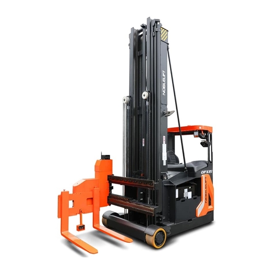
INSTRUCTION MANUAL
Battery powered lateral- and front-stacking truck (three sides)
OPX15
WARNING
Do not use the truck before reading and
understanding these operating instructions of this
manual.
NOTE:
• Please check the designation of your
present type at the last page of this
manual as well as on the ID-plate.
• Keep it for future reference.
This truck can only be used in factories,
tourist attractions, and amusement parks.
Version 12/2020
OPX15-SMS-001-EN
Advertisement
Table of Contents

Related Manuals for Noblelift OPX15


Summary of Contents for Noblelift OPX15
- Page 1 INSTRUCTION MANUAL Battery powered lateral- and front-stacking truck (three sides) OPX15 WARNING Do not use the truck before reading and understanding these operating instructions of this manual. NOTE: • Please check the designation of your Version 12/2020 present type at the last page of this OPX15-SMS-001-EN manual as well as on the ID-plate.
- Page 2 FOREWORD Before operating the lateral- and front-stacking truck (three sides), read this original instruction manual carefully and understand the usage of the truck completely. Improper operation could cause danger. This manual describes the usage of different battery powered lateral- and front-stacking truck. When operating and servicing the truck, make sure that it applies to your type.
-
Page 3: Table Of Contents
Table of Contents CORRECT APPLICATION ......................... 4 DESCRIPTION OF THE TRUCK ....................... 5 a. Overview of the main components ....................5 b. Main technical data ........................... 7 c. Description of the safety devices and warning labels (Europe and other, excepting USA) ... 10 d. - Page 4 13. Declaration of Conformity (valid for sale in the EU) ................. 50 [GB] CE Declaration of Conformity ......................50...
-
Page 5: Correct Application
1. CORRECT APPLICATION To ensure the safety of personal and equipment, drivers shall observe the following precautions: Only drivers who have been trained and hold a industrial trucks driving license can drive this truck; This truck is suitable for hard and flat indoors floor conditions; Check the control and alarm devices before driving this truck. -
Page 6: Description Of The Truck
2. DESCRIPTION OF THE TRUCK Overview of the main components Fig. 1: Overview of main components Seat assembly Display Accelerator pedal Overhead guard Brake pedal 10. Mast Safety pedal switch 11. Load wheel Central control unit 12. Guide roll Steering wheel 13. - Page 7 Main technical data Fig 2: Structure schematic drawing...
-
Page 8: Main Technical Data
Table 1: Main technical data for standard version Type sheet for industrial truck acc. to VDI 2198 Manufacturer (abbreviation) NOBLELIFT Manufacturer’s type designation OPX15 Drive: electric (battery type, mains, ...), diesel, petrol, Battery type fuel gas Operator type: hand, pedestrian, standing, seated,... - Page 9 Operating pressure Oil volume l /min Sound pressure level at driver’s seat <70 dB (A) Steering design Electronic steering Note Table of working device parameters of OPX15 Lift Free lift Height, mast lowered Height, mast extended Designation Weight kg 5500 1930...
-
Page 10: Description Of The Safety Devices And Warning Labels (Europe And Other, Excepting Usa)
Description of the safety devices and warning labels (Europe and other, excepting USA) Warning labels: OPX15 OPX15 前 移 式 叉 车 特 种 设 备制 造 许 可 证 编号 : T S2 51 03 50 -2 02 1 Tel :4 00 8—... - Page 11 Safety devices: Fig 4: Safety devices Emergency button: Please press this button immediately to cut of the power supply when the truck is out of control, all lifting-, lowering-functions will be stopped. Key switch: To prevent against unauthorized access, turn the key counterclockwise and pull it out. Brake: To stop the truck when it is driving.
-
Page 12: Identification Plate (Id-Plate)
Equipment Code Manufacturer Art. No. This truck is only used in factories, tourist attractions and tourist sites. Manufacturer: Noblelift Intelligent Equipment Co., LTD No.528, Changzhou Road, Taihu Street, Changxing County, Zhejiang Province Fig 5: Identification plate 3. WARNINGS, RESIDUAL RISK AND SAFETY INSTRUCTIONS •... -
Page 13: Commissioning, Transporting, Decommissioning
• The truck is intended to be used on hard and flat ground indoors whose roughness should be within 1cm/m • The operator should hold driving license and have been trained; • When operating the truck, the operator has to wear safety shoes. •... -
Page 14: Loading And Unloading/ Transportation
Table 2: Weight of truck chassis and mast Truck Model OPX15 Truck chassis pack weight [kg] 3600 Truck chassis pack size [mm] 2260x1520X2200 Lift height H3 [mm] 5500 6500 7500 8500 9500 10500 Mast pack weight [kg] 2220 2340 2460... -
Page 15: Storage
Lower the fork and park the truck securely. Fasten the truck according to Fig. 8, put the wood blocks under the driving cab to prevent damage to the drive wheel during transporting. Fig 8: Fixing points for transportation Storage Lower the fork to the lowest position, as shown in figure 8, padded the cabin with sleepers to lift the drive wheel to prevent damage due to long-term storage. -
Page 16: Operational Instructions
• Check the functions of foot brake. • Check the lifting and lowering functions. • Check the seat is assembled tightly. • Check the function of horn. • Check if all bolts and nuts are tightened firmly. • Check the function of key switch. •... -
Page 17: Power-On The Truck
It is used to control the start/ acceleration/ deceleration/ stop of the truck. Accelerator It is used to control the service brake of the truck. Foot brake pedal It is a safety switch, the left foot should always be placed on this switch Safety pedal switch when operating the truck. -
Page 18: Steering
Carefully drive the truck to the destination. Observe the route conditions and adjust the travelling speed by operating the accelerator pedal. This truck is equipped with adequate safety equipment to avoid accidents. When the height of the fork is higher than the free lifting height, the speed of the truck will be reduced for smooth travelling and safe work. -
Page 19: Lifting
Fig. 10: Residual lift diagram g. Lifting DO NOT OVERLOAD THE TRUCK! THE MAXIMUM CAPACITY IS 1500KG REFERRING TO THE IDENTIFICATION PLATE. LIFT THE LOAD THAT IS INDICATED AND ALLOWED IN RESIDUAL LIFT DIAGRAM ONLY, OTHERWISE IT MAY DAMAGE THE TRUCK. Pull the l (7) backwards to lift the fork until it reaches your ifting and lowering control stick... -
Page 20: Fork Rotation (Left/Right)
j. Fork rotation (left/right) Push the left and right rotation control stick (9) forwards, the fork rotates to the left. Pull the left and right rotation control stick (9) backwards, the fork rotates to the right. k. Fork rotation and lateral movement (left/right) Push the left and right joint operation control stick (14) forwards, the fork rotates to the left, and the lateral movement frame moves to the right. -
Page 21: Battery Changes And Replacement
7. BATTERY CHANGES AND REPLACEMENT • Only qualified personnel are allowed to service or charge the batteries. The instructions of this manual and battery manufacturer’s manual must be observed. • The batteries are lead acid batteries. • Recycling of batteries must comply with national regulations. •... -
Page 22: Replacement
Replacement Park the truck safely, follow the steps described below to pull out the battery, turn off the key switch (2), press the emergency button (1), disconnect the battery connector (15), and lift the battery directly. Be aware that battery may tip over if the equipment is unsafe. Installation is in reverse order of removal. Please follow the steps below: Step 1: Move the truck to the battery carrier and align with each other. -
Page 23: Battery Indicator And Alarm
Battery indicator and alarm Fig. 13: Display State of charge (SOC) of the battery is displayed on the right side of the indicator, if the battery is fully charged, the indicator displays 100% (10 segments), when SOC of battery is 20%, the battery symbol will light on (the sixth one from left in figure 11), indicating the battery needs charging. -
Page 24: Regular Maintenance
8. REGULAR MAINTENANCE • Only qualified and trained personnel are allowed to do maintenance to this truck. • Remove load from fork and lower fork to the lowest position before maintenance. • If you need to lift the truck, follow chapter 4b by using designated lashing or jacking equipment. - Page 25 • Test the display • Check, if correct fuses are used • Test the warning signal • Check the contactor (s) • Check the frame leakage (insulation test) • Check function and mechanical wear of the accelerator • Check the electrical system of the drive motor Braking system •...
-
Page 26: Lubricating Points
Lubricating points Lubricate the marked points according to the maintenance checklist. The required grease specification is: DIN 51825, standard grease. Fig 14: Lubricating points... -
Page 27: Check And Refill Hydraulic Oil
Check and refill hydraulic oil It is recommended to use the hydraulic oil: • Type: H-LP 46, DIN 51524 • Viscosity: 41.4 – 47 Waste material like oil, used batteries or others must be probably disposed and recycled according to the national regulations and brought to a recycling company if necessary. -
Page 28: Trouble Shooting
9. TROUBLE SHOOTING • If the truck has malfunctions, follow the instructions mentioned in chapter 6. Table 5: Trouble shooting TROUBLE CAUSE MAINTENANCE Lift only the max. capacity, mentioned on the Load weight too high ID-plate. Battery discharged Charge the battery. Lifting fuse failure Check and eventually replace the lifting fuse. -
Page 29: Wiring/Circuit Diagram
10. WIRING/CIRCUIT DIAGRAM Electrical circuit diagram Fig. 16: Electrical circuit diagram... - Page 30 Table 6: Description of electrical components Code Item Code Item Battery 48V Battery extraction monitor switch Emergency button Mast limit switch Towering motor Mast speed limit switch Pump motor Move forward limit switch Steering motor Move back limit switch Speed limit switch for moving back Towering controller and forth Pump controller...
-
Page 31: Hydraulic Diagram
11. HYDRAULIC DIAGRAM Fig. 17: Hydraulic diagram... -
Page 32: Diagnostics And Troubleshooting
12. DIAGNOSTICS AND TROUBLESHOOTING These controllers detect a wide variety of faults or error conditions. Faults can be detected by the operating system or by the VCL code. This section describes the faults detected by the operating system. Diagnostics information can be obtained in either of two ways: (1) by reading the display on a hand-held or PC programmer or (2) by observing the fault codes issued by the Status LEDs. - Page 33 Controller has detected a fault. 2-digit code flashed by Red LED and yellow LED flash yellow LED identifies the specific fault; one or two flashes by alternately red LED indicate whether first or second code digit will follow. Troubleshooting The troubleshooting chart provides the following information on all the controller faults: •...
- Page 34 1232SE drive controller and pump motor controller troubleshooting table...
- Page 42 1222 Steering motor controller troubleshooting table...
- Page 51 CE-DD-002 13. Declaration of Conformity (valid for sale in the EU) [GB] CE Declaration of Conformity The signatory hereby declares that the specified machine conforms to the EU Directive 2006/42/EC (Machine Directive) and 2014/30/EU (Electro-Magnetic Compatibility, EMC) including their amendments as translated into national legislation of the member countries. The signatory is individually authorized to compile the technical documents.
- Page 52 [PL] DEKLARACJA ZGODNOŚCI WE Niżej podpisani deklarują, że poniżej opisana maszyna spełnia wymagania określone w dyrektywach Europejskich 2006/42/EC (Dyrektywa Maszynowa) i 2014/30/EU (Kompatybilności elektromagnetycznej - EMC) wraz z ich późniejszymi zmianami oraz odpowiednimi rozporządzeniami mającymi na celu przeniesienie tych dyrektyw do prawa krajów członkowskich. Sygnatariusz jest indywidualnie upoważniony do zestawiania dokumentacji technicznej. [RO] DECLARAŢIE DE CONFORMITATE CE Subsemnaţii adeveresc prin prezenta că...
Need help?
Do you have a question about the OPX15 and is the answer not in the manual?
Questions and answers