Table of Contents
Advertisement
Quick Links
INSTRUCTION HANDBOOK
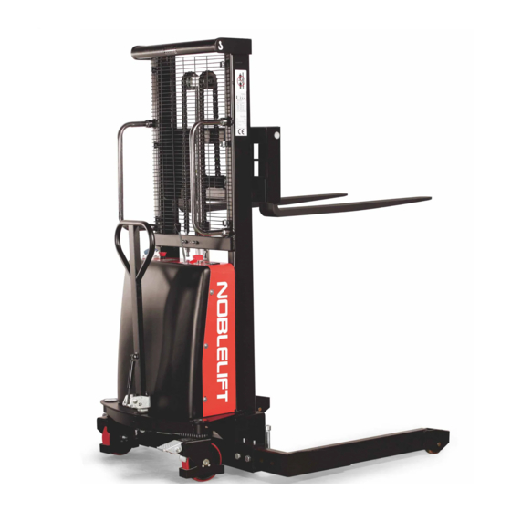
SEMI-POWER STACKER SPN22
WARNING
Do not use the electric truck before reading
and understanding these operating
instructions.
NOTE:
Please check the designation of your
present type at the last page of this
document as well as on the ID-plate.
Keep for future reference.
Version 03/2017
SPN22A-SMS-001-US
Advertisement
Table of Contents

Related Manuals for Noblelift SPN22


Summary of Contents for Noblelift SPN22
- Page 1 INSTRUCTION HANDBOOK SEMI-POWER STACKER SPN22 WARNING Version 03/2017 Do not use the electric truck before reading SPN22A-SMS-001-US and understanding these operating instructions. NOTE: Please check the designation of your present type at the last page of this document as well as on the ID-plate.
-
Page 2: Unpacking And Inspection
& & Please read and save these instructions. Read carefully before attempting to assemble, install, operate or maintain the product described. Protect yourself and others by observing all safety information. Failure to comply with instructions could result in personal injury and/or property damage! Retain instructions for future reference. -
Page 3: Specifications
Specifications Maximum Capacity/ Load Center Model Drive Lift Rated Load (Q) Distance © SPN22A(63IN) Manual Pedestrian 2200 SPN22A(98IN) Manual Pedestrian 2200 SPN22A(118IN) Manual Pedestrian 2200 SPN22A(137IN) Manual Pedestrian 2200 Lifting Weight Lifting Speed Parking Motor Model (incl. Battery) (laden/unladen) Brake Rating Battery SPN22A(63IN) - Page 4 Description SPN22A(63IN), SPN22A(98IN) ,SPN1030A-N, SPN22A(137IN) Tire material Polyurethane wrapped steel Tire size (front dia.) 4” Tire size (rear dia.) 7” Number of wheels 2 front wheels, 2 rear wheels Table 2 – Wheel Dimensions Lifting Height (H)* Capacity at 24” Center Capacity at 28”...
- Page 5 REPAIR Only professionally trained and specifically authorized individuals are permitted to repair or modify any part of the stacker. Any changes to installed switches and safety devices by the operator are strictly prohibited. IMPORTANT: All spare parts from the manufacturer are inspected by Quality Assurance Authorities. To ensure the safety and reliability of the stacker’s operation, only manufacturer approved spare parts may be used.
- Page 6 Operating on slopes is permitted only when they are recognized lanes, when they are clean and non-slip surfaces, and when the technical data of the stacker permits safe driving on such slopes or inclines. Cargo must face in an upward direction of slope.
- Page 7 APPLICATION CONDITIONS Ambient temperature operation range: 40ºF (5ºC) to 105ºF (40ºC). DIMENSIONS (See Tables 1 and 2 on page 2 and 3 for Wheel and Stacker Dimensions.) During continuous operation of the stacker in conditions below 40ºF (5ºC), or in low temperature and high humidity, special protections should be taken to protect electronic gauges and circuitry.
-
Page 8: Operation
Figure 3 – Straddle Leg Assembly FORK ASSEMBLY Use snap ring pliers to remove the retaining ring and the fork carriage shaft from the carriage. Place the forks so that the holes of the forks match up to the hole for the carriage shaft. You may need someone to help hold the forks in place. - Page 9 Figure 5 – Control Panel STARTING THE STACKER Confirm that no persons are in the danger area before starting and operating the stacker or lifting any cargo. ROUTINE CHECKS BEFORE START UP Check for any external stacker defects (especially wheels and pallets). ...
- Page 10 CARGO LOADING/UNLOADING Before loading cargo, the operator must confirm that cargo is properly placed on the pallet and the weight of the cargo is within the rated load capacity of the stacker. Carrying full capacity loads for extended periods is prohibited.
- Page 11 performed while wearing protective goggles and clothing to avoid bodily contact with the battery acid solution. If clothing, skin or eyes accidentally come into contact with the electrolyte in battery, liberally flush the affected parts with clean water and consult a doctor immediately. Any spilled electrolyte must be neutralized as soon as possible.
- Page 12 The discharge status is indicated by ten red LED segments. Battery discharged Battery charged Battery discharge indicator Only when the battery is properly charged, the most right LED lit. As the battery’s state-of-charge decreases, successive LEDs light up, only one on at a time. ...
- Page 13 WELDING To avoid damage of electric and electronic assemblies, assemblies should be removed from the stacker before welding. INSTALLATION After repairing or replacing hydraulic components, electric elements, and electronic assemblies, confirm that all components are at original positions before resuming use. WHEELS Wheel quality greatly affects the stability and driving performance of the stacker.
- Page 14 Visually inspect for any blockages in the loading wheels • Check for any wear or damage to the edges of forks • and pallet Check performance • Check for any leakage or damage on all joints ‡ • Check for leakage or damage to hydraulic cylinder, •...
-
Page 15: Troubleshooting Chart
Apply oil or grease to fittings as needed. Consult detailed Lubrication List to lubricate the stacker. Recharge the battery. Disconnect and clean the battery. Apply dielectric grease to the battery electrodes. NOTE: In addition to the above, instructions provided by the battery supplier should also be observed. MEASURES TO BE TAKEN DURING STORAGE Every two months: charge the battery.
Need help?
Do you have a question about the SPN22 and is the answer not in the manual?
Questions and answers