
Related Manuals for Noblelift SPM1030


Summary of Contents for Noblelift SPM1030
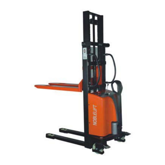
- Page 1 SERVICE & MAINTENANCE MANUAL Semi-Electric Stacker Version 06/2013 SPM1030 -SHFW-001...
-
Page 2: Table Of Contents
CONTENT FOREWORD .............................. 3 GENERAL ............................4 1.1 INTRODUCTION – MAINTENANCE SAFETY PRECAUTIONS ..........4 1.2 MEASUREMENT CONVERSIONS ....................8 SPECIFICATION ..........................13 2.1 OVERVIEW ..........................13 2.2 SPARE PARTS LIST ........................14 2.3 SPECIFICATION SHEET ......................17 2.4 LUBRICATION ........................... 19 HYDRAULIC SYSTEM ........................ -
Page 3: Foreword
FOREWORD Proper operation, maintenance, troubleshooting and repairs are necessary to preserve the performance of the pallet truck over a long period and ensure that fault and breakdowns do not occur. The purpose of this service manual is to provide necessary information especially in inspections, repair and maintenance. -
Page 4: General
1. GENERAL 1.1 INTRODUCTION – MAINTENANCE SAFETY PRECAUTIONS Maintenance work may cause injuries. Always take care to perform work safe, at least observing the following. It is of utmost importance that maintenance personnel pay strict attention to these warnings and precautions to avoid possible injury to themselves, others or damage to the equipment. A maintenance program must be followed to ensure that the machine is safe to operate. - Page 5 It should be noted that the machines hydraulic systems operate at extremely high potentially dangerous pressures. Every effort should be made to relieve any system pressure prior to disconnecting or removing any portion of the system. Relieve system pressure by cycling the applicable control several times with the engine(motor) stopped and ignition on, to direct any line pressure back into the reservoir.
- Page 6 Always use the grades of grease and oil recommended by NOBLELIFT choose the viscosity specified for the ambient temperature. Exhaust gas is dangerous provide ventilation when working in a closed space. Avoid breathing dust that may be generated when handling components containing asbestos fibers.
- Page 7 When changing the oil or fitter, check the drained oil and filter for any signs of excessive metal particles or other foreign materials. Always use NOBLELIFT genuine parts for replacement. ENSURE REPLACEMENT PARTS OR COMPONENTS ARE IDENTICAL OR EQUIVALENT TO ORIGINAL PARTS OR COMPONENTS. ...
-
Page 8: Measurement Conversions
1.2 MEASUREMENT CONVERSIONS Length Unit mile 0.01 0.00001 0.3937 0.03281 0.01094 0.000006 0.001 39.37 3.2808 1.0936 0.00062 100000 1000 39370.7 3280.8 1093.6 0.62137 2.54 0.0254 0.000025 0.08333 0.02777 0.000015 30.48 0.3048 0.000304 0.3333 0.000189 91.44 0.9144 0.000914 0.000568 mile 160930 1609.3 1.6093 63360... - Page 9 Pressure Unit kgf/cm Pa=N/m lbf/in lbf/ft kgf/cm 0.98067 98066.5 98.0665 14.2233 2048.16 1.01972 100000 14.5037 2088.6 Pa=N/m 0.00001 0.001 0.001 0.00015 0.02086 0.01020 0.01 1000 0.14504 20.886 lbf/in 0.07032 0.0689 6894.76 6.89476 lbf/ft 0.00047 0.00047 47.88028 0.04788 0.00694 kgf/cm =735.56 Torr(mmHg)=0.96784atm Standard tightening torque The following charts give the standard tightening torques of bolts and nuts.
- Page 10 INCH TABLE 4T, 5T Classification Bolt type Bolt size Torque kgf · m (lbf · ft) Torque kgf · m (lbf · ft) 0.6 ± 0.06 1.7 ± 0.2 5/16 1.2 ± 0.12 3.0 ± 0.3 2.0 ± 0.20 5.6 ± 0.5 7/16 3.2 ±...
- Page 11 O – ring Plug PF THREAD Thread Torque (kgf·m) 1.1 ± 0.1 2.6 ± 0.2 4.6 ± 0.3 8.5 ± 0.4 19 ± 1.0 33 ± 2.0 TORQUE FOR SWIVEL NUT WITH O-RING Connector O – ring Swivel – nut hose Tube O.D (inch) Thread (in)
- Page 12 APPROXIMATE CONVERSIONS Conv Non–SI Conv Unit Factor Unit Factor Unit Torque × 8.9 × 0.113 Newton meter (N·m) = ln·in = N·m × 0.74 × 1.36 Newton meter (N·m) = lb·ft. = N·m × 0.102 × 7.22 Newton meter (N·m) = kg·m = lb·ft.* Pressure (Pa = N/m...
-
Page 13: Specification
2. SPECIFICATION 2.1 OVERVIEW Hydraulic system Electric box Steering system& wheel kits Power pump unit Fork carriage Mast system... -
Page 14: Spare Parts List
2.2 SPARE PARTS LIST... - Page 15 Description Qty. Description Qty. Inner Mast Locking Ring (2.5G) Inner Mast Shaft (3.0G) Locking Ring Brake Bearing Spring Roller For Chain Bolt Locking Ring Sprocket Wheel Screw 163A Sprocket Wheel Washer Seat of Turning Wheel Roller Big Wheel Bolt Bearing Bolt Oil holder Crutch of Idler Pulley...
-
Page 16: Specification Sheet
2.3 SPECIFICATION SHEET 2.3.1 RESIDUAL CAPACITY AT DIFFERENT LIFTING HEIGHT Lifting height Actual load capacity ( Q ) kg 1500 1000 2500 1000 3000 Load center distance ( C ) 2.3.2 TECHNICAL FEATURE... - Page 17 Type SPM1030( Power: electric (battery), diesel, gasoline, gas, hand Hand Driving mode(hand, pedestrian, stand-on, sit-down, unit-pick) Pedestrian Rated load capacity Q (kg) 1000 Load center distance c (mm) Wheelbase y (mm) 1210 Service weight (with battery) Tire type: solid rubber, high-performance elastomer, nylon, PU...
-
Page 18: Lubrication
2.4 LUBRICATION Hydraulic oil Hydraulic oil must have anti-wear qualities at least. It is not advisable to mix oils of different brands or types, as the may not contain the same required additives or be of comparable viscosities. Name: Thickened hydraulic oil. ISO Viscosity Grade Characteristics unit... -
Page 19: Hydraulic System
3. HYDRAULIC SYSTEM 3.1 OPERATION OF CYLINDER STRUCTURE Remove 8 screws on the protecting meshwork Remove 2 dome cap nuts and 2 hexagon nuts and remove it with wrench... - Page 20 Now you can take away the hoop fixing the Remove the screw of the hydraulic pipe cylinder lift the fork up to a certain height and support the Remove the screw on the seat for chain inner mast with a stick The oil will spill over when removing;...
-
Page 21: Electric Box
4. ELECTRIC BOX 4.1 ELECTRIC DIAGRAM WIRING DIAGRAM Electric diagram SPM 10 Description Qty. Parts No. Code Model Other Plug DQ-40 3×0.75 Alternative Charger DQ-108 12V/20A QQE240-5CH20-26-A Alternative Light of charger DQ-110 Inside Battery DQ-105 12V/150Ah Power switch DQ-106 ZDK31-250 Fuse 200A DQ-46 200A... - Page 22 CABLE SYSTEM...
-
Page 23: Tool For Repairing The Pin Of Electric Plug
4.2 TOOL FOR REPAIRING THE PIN OF ELECTRIC PLUG Figure Application Tool for removal of pins / sleeves Tool for application of pins / sleeves Tool for release of lock Tool for application of secondary locking 2 – pole Tool for application of secondary locking 4 – pole Tool for removal of pins / sleeves... -
Page 24: Replace The Electric Parts
4.3 REPLACE THE ELECTRIC PARTS Switch off electrical power before repair! Remove 4 screws (each 2 on left and right) on the Cover , dismantle the washer, then you can remove the cover. Turn the mushroom head of the emergency button;... - Page 25 Now you can open the main cover. After dismantle the connector of charger, key switch, emergency button and battery indicator, you can remove the cover. All electric parts appear. REPLACE THE BATTERY INDICATOR Remove the 4 cables at the back of the indicator Turn counter-clockwise the screw fixing the hoop, and then you can remove the indicator from outside.
- Page 26 REPLACE THE KEY SWITCH Turn counter-clockwise the screw of key switch with wrench and then you can remove it from outside REPLACE THE EMERGENCY BUTTON After dismantle the mushroom head and main cover you can see the frame of emergency button, remove 2 screws and remove 2 cables connecting to the emergency button, then you can replace it.
- Page 27 Magnetic valve and replace it 4.4 OPERATION OF THE BATTERY The size of battery is according to English BS standard. Specification Rate SPM1030 Rated voltage 12V(X1) Capacity (5 hours) 150Ah Overall size (L*W*H)(mm) 523×238×283...
- Page 28 100% DURATION OF DISCHARGING LIFE TEST CURVE ( ENVIRONMENTAL TEMPERATURE = 25 CHARGING CURVE...
-
Page 29: Battery
REPLACE THE BATTERY Remove bolts, nuts, washers, which fix the power cable (+, -) to the battery. Remove the screws fixing the hoop, press the handle downward and you can remove the battery and replace it. Don’t let the wrench to touch the other pole, otherwise it will cause short-circuit. Avoid kicking by the rebound handle. -
Page 30: Main Prodyct Specification
Dismantle 2 screws fixing cable B+ and B-, and remove the connector, remove 2 screws at the bottom of the charger, then you can remove and replace it. 4.4.1 MAIN PRODYCT SPECIFICATION Max. output Output current Input voltage Output voltage Combined regulation power range... - Page 31 Output characteristics Item Technical requirements Unit Remark Fast charge voltage 14.2 Floating voltage 14.7 Maintain voltage 14.7 Constant current Cross regulation ±3% Vin=220Vac,rated ≥80% Power efficiency load Protection characteristics Item Technical requirements Remark Output over Lockout voltage protection The charger software limits the maximum Software over output voltage to a level suitable for the voltage protection...
- Page 32 Charger(LED) indicator Item Status LED Remark Waiting model LED OFF ALWAYS Fast charging LED(RED)ON ALWAYS Floating charge LED(YELLOW)ON ALWAYS Completely LED(GREEN)ON ALWAYS Charge Safety & EMC Standard Item Remark (or testing condition) Electric No breakdown strength Input—output 1500Vac/10mA/1min test ≥10MΩ@500Vdc Input—ground Isolation resistance...
- Page 33 Environmental testing requirements Item Technical specification Remark High temperature +40℃ Features ok ambient operating Low temperature -10℃ Features ok ambient operating High temperature Work normally after recovery under +70℃ storage normal temperature for two hours Low temperature Work normally after recovery under -40℃...
- Page 34 2)、 Output terminator diagram & definition: 3)、WEIGHT: (ABOUT 1.25Kg) 8. Package, transportation & storage 1)、Package There are product name, model, making of manufacturer, safety approval, and manufacturing date on the package box, and manual of specifications and packing list in the package box. 2)、Transportation Suit for transportation by truck,ship,and plane.
- Page 35 11. Label 12. CHARGE CURVE...
- Page 36 13. Mechanical outline...
-
Page 37: Steering System& Wheel Kits
5. STEERING SYSTEM& WHEEL KITS 5.1 REMOVE THE AIR SPRING Remove the screws fixing the protecting Remove 2 screws under the handle with Allen cover of handle, and take it away with hands wrench, then you can remove the air spring Remove the screws fixing the shaft with screwdriver... -
Page 38: Operation Of The Wheel
5.2 REMOVE THE HANDLE Strike out the shaft with hammer and puncher, and then you can remove the handle. Hold tight the punch and avoid striking by the hammer! 5.2 OPERATION OF THE WHEEL 5.2.1 OPERATION OF THE BIG WHEEL (LEFT) Support the mast with a block to keep the big Remove the screw on the cap, and then you can wheel hanging... -
Page 39: Operation Of The Footbreak
5.2.2 OPERATION OF THE FOOTBREAK Remove the Retaining ring with spring pliers Strike out the shaft, then you can remove the foot plate. Hold tight the punch and avoid striking by the hammer! Remove the bolt, you can see the spring, and then you can remove the whole brake. -
Page 40: Operation Of The Loading Roller
Remove the screw on the cap, and then you can Now follow the steps of removing left wheel, you remove the cap, bearing, bolt and wheel. can remove the right wheel and the chain 5.2.3 OPERATION OF THE LOADING ROLLER Support the mast with a block to keep the loading Strike out 4 elastic pin with hammer and puncher, roller hanging... -
Page 41: Power Pump Unit
Color changed into dark brown Oxidized Replace oil. Clear but there are small black Fine Mixed with other particles Use after filtering. spots Type: MD12160 Item SPM1030 Rated voltage Rated output 1.6kw R.P.M 2950 rpm Rated current 200 A Rated hour 2 min. - Page 42 PUMP STATION OPERATION Remove 3 screws on the relay and 1 screw on the motor, and then remove the cables. keep the fork at the bottom, and remove the Dismantle the connector of cables 7-, 5-2-, 5-1-, cut joint of the hydraulic pipe off the plastic band.
-
Page 43: Clean Oil Tank And Filter
HYDRAULIC PIPE For shocking, the joint of the hydraulic pipe and hydraulic pipe might be loosed and leak oil, so usually check and tighten it The oil will spill over when removing; keep clean for the stacker and yourself! 4.3 CLEAN OIL TANK AND FILTER Plug Screw of port for adding oil is ventilating. - Page 44 Remove out the pump station. Loosen the hoop Remove the oil tank Remove the suction filter Cleaning of oil tank and filter. Clean the Fix plate for valve etc. Clean up with compressed air and inspect if the filter is stopped or damaged.
- Page 45 OPERATION OF THE CONTROL STICK After remove the screw fixing the control stick you can remove it, and then remove 4 screws to dismantle the coverplate of control stick. Loosen the screw fixing the control stick and Remove 2 screws fixing the seat of micro switch. remove it.
- Page 46 After separate the seat of micro switch, remove the retaining ring on the screw with spring pliers Now you can see the spring inside and replace it. SEPARATION OF THE MOTOR OF PUMP STATION For the electric current of the Relay for the lifting motor is very big, and work continually hourly, the contact terminal of the relay is easy damaged.
- Page 47 Remove 2 screws fixing the relay onto motor and remove the relay Remove 2 screws on the top of motor, then press the tuber on the top cap and remove it, now you can see the internal parts of motor. Remove the screw fixing the carbon brush, and then remove the clip fixing it, now you can remove the carbon brush.
- Page 48 Remove 4 screws on the top plate with wrench and screwdriver. Now you can remove the stator of the motor, and then you can remove the rotor of the motor, and replace the part you want to.
- Page 49 SEPARATION OF THE VALVE PLATE The oil will spill over when removing; keep clean for the stacker and yourself! Remove one-way valve: Dismantle the screw of one-way valve with wrench and remove it. Remove flow-control valve: Dismantle the screw of flow-control valve with wrench and remove it. Remove the joint of hydraulic pipe: loosen it with wrench and remove it with hand.
-
Page 50: Maintenance Check List
7. MAINTENANCE CHECK LIST 7.1 HYDRAULIC OIL Check oil mass once every six mouths. Suggest to use No.32 hydraulic oil (GB11118-89), its kinematic viscosity is 32cSt when it is on 400, the total amount is about 4.0 litre. 7.2 REGULAR MAINTENANCE In order to keep an good using status, necessary check and maintenance everyday is suggested. -
Page 51: Trouble Shooting
8. TROUBLE SHOOTING Trouble Clause Fixing Methods The forks cannot be lifted hydraulic is not Pour in the oil to the maximum height enough Without hydraulic oil Fill in the oil The forks cannot be lifted ...
Need help?
Do you have a question about the SPM1030 and is the answer not in the manual?
Questions and answers