Table of Contents
Advertisement
Quick Links
INSTRUCTION MANUAL
Reach Truck
RT16/20P-CS
WARNING
Do not use the reach truck before reading and
understanding these operating instructions.
NOTE:
Please check the designation of your
present type at the last page of this
document as well as on the ID-plate.
Keep it for future reference.
This truck can only be used in the factory,
tourist attractions and amusement areas.
Version 09/2023
RTxxP-CS-SMS001EN
Advertisement
Table of Contents
Troubleshooting

Related Manuals for Noblelift RT16P-CS


Summary of Contents for Noblelift RT16P-CS
- Page 1 INSTRUCTION MANUAL Reach Truck RT16/20P-CS WARNING Do not use the reach truck before reading and understanding these operating instructions. NOTE: Version 09/2023 Please check the designation of your RTxxP-CS-SMS001EN present type at the last page of this document as well as on the ID-plate. ...
- Page 2 FOREWORD Before operating the reach truck, read this ORIGINAL INSTRUCTION MANUIAL carefully and understand the application of the truck completely. Improper operation could create danger. This manual describes the usage of different electric reach trucks. When operating and servicing the truck, make sure, that it applies to your type.
-
Page 4: Table Of Contents
TABLE OF CONTENTS 1. CORRECT APPLICATION ........................4 2. TRUCK DESCRIPTION ......................... 5 a. Overview of the main components ..................... 5 b. Main technical data ..........................7 c. Description of the safety devices and warning labels (Europe and other, excepting USA) ....11 d. -
Page 5: Correct Application
1. CORRECT APPLICATION To ensure the safety of personal and equipment, drivers shall observe the following precautions: Only operator who has been trained and has the license is allowed to operate the truck; The truck is applicable for hard and flat indoors floor; Check the control and alarm devices before driving. -
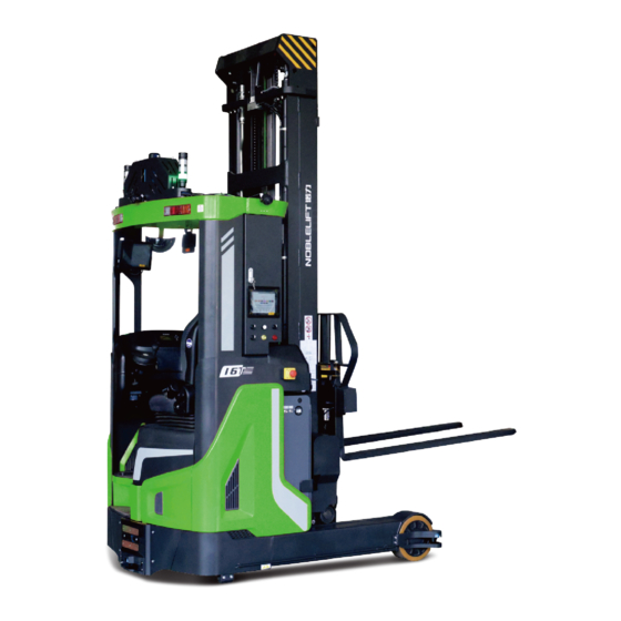
Page 6: Truck Description
2. TRUCK DESCRIPTION Overview of the main components Fig. 1: Overview main components Seat assembly 13. Mast reach (extend/retract) control Accelerator pedal 14. Mast tilt (up/down) control Brake pedal 15. Turn signal switch Safety pedal switch 16. Horn button Control unit 17. -
Page 7: Main Technical Data
Main technical data β α Fig. 2: Structure schematic drawing... - Page 8 Table 1: Main technical data for standard version Type sheet for industrial truck acc. to VDI 2198 Manufacturer’s type designation RT16P RT20P RT20PH Drive: electric (battery type, Battery Battery Battery mains, ...), diesel, petrol, fuel gas Operator type: hand, pedestrian, Seated Seated Seated...
- Page 9 lengthways 4.35 Turning radius (mm) 1650 1750 1840* 4.37 Length across wheel arms (mm) 1780 1900 2000* Travel speed, laden/ unladen km/h 10.5/10.5 10.5/10.5 10.5/10.5 Lift speed, laden/ unladen 0.35/0.50 0.35/0.50 0.35/0.50 Lowering speed, laden/ unladen 0.45/0.45 0.45/0.45 0.45/0.45 Reaching speed, laden/ unladen 0.10/0.10 0.10/0.10 0.10/0.10...
- Page 10 Standard mast designs, RT 16P Lift Free lift Lowered mast height Extended mast height Designation 4500 1563 2235 5410 5000 1730 2400 5910 5500 1897 2568 6410 6000 2063 2735 6910 6500 2230 2900 7410 Three stage mast 7000 2397 3068 7910 FFL (full free lift)
-
Page 11: Description Of The Safety Devices And Warning Labels (Europe And Other, Excepting Usa)
Description of the safety devices and warning labels (Europe and other, excepting USA) Warning labels: 前 移 式 叉 车 特 种 设 备 制 造 许 可 证 编 号 : TS 2 51 0 35 0 -2 0 21 T el : 40 0 8—... - Page 12 Safety devices Fig. 4: Safety devices Emergency switch: Press this button immediately to cut off the power supply when the truck is out of control, and all lifting-, lowering-functions will be stopped. Key switch: To prevent against unauthorized access, turn the key counterclockwise and pull it out. Service brake: To stop the truck when it is driving.
-
Page 13: Location Of Vin (Vehicle Identification Number)
Location of VIN (Vehicle Identification Number) Fig. 5: Location of VIN (Vehicle Identification Number) The VIN (Vehicle Identification Number) is located on the chassis, mast and forks of the truck, and the truck equipped with hook type fork also has the corresponding VIN on the fork. -
Page 14: Identification Plate (Id-Plate)
Identification plate (ID-plate) Identification plate Fig. 6: Location of the ID plate Designation, type Battery weight Min./Max in kg Serial number Nominal power in kW Rated capacity in kg Load center distance in mm Supply voltage in V Manufacturing date (MM/YY) Net weight in kg (without battery) Option Name and address of manufacturer) -
Page 15: Warnings, Residual Risk And Safety Instructions
3. WARNINGS, RESIDUAL RISK AND SAFETY INSTRUCTIONS DO NOT Use truck in environments with explosive gas, explosive dust or acid and alkali corrosion; Use truck in the environment with poor outdoor or ground conditions; Put feet or hands under or inside the lifting mechanism; ... -
Page 16: Commissioning, Transporting, Decommissioning
4. COMMISSIONING, TRANSPORTING, DECOMMISSIONING Commissioning After receiving our new reach truck or for re-commissioning you have to do following before (firstly) operating the truck: Check if all parts are included and not damaged Mast installation (please follow the instructions to install mast); ... -
Page 17: Lifting By Crane/ Transporting
Table 2: Chassis weight and mast weight Type RT16P RT20P RT20PH Chassis pack weight [kg] 2350 2550 3300 Chassis pack size [mm] 1900x1400X2300 2100x1400X2300 2100x1600X2300 Lift height H3 [mm] 5500 7500 9500 5500 7500 9500 10500 11500 12500 Mast pack weight [kg] 1300 1450 1600... -
Page 18: Storage/ Decommisioning
Transporting ALWAYS FASTEN THE TRUCK SECURELY WHEN TRANSPORTED ON A LORRY OR A TRAILER. Lower the forks and park the truck securely. Fasten the truck according to Fig. 10, put the wood blocks under the driving cab to prevent damage to the driving wheel in transporting. -
Page 19: Regular Inspection
5. REGULAR INSPECTION This chapter describes pre-shift checks before putting the truck into operation. Regular inspection is effective to find the malfunction or fault on this truck. Check the truck on the following points before operation. REMOVE THE LOAD FROM THE TRUCK AND LOWER THE FORKS. DO NOT USE THE TRUCK IF ANY MALFUNCTION IS FOUND. -
Page 20: Operation Instructions
6. OPERATION INSTRUCTIONS a. Overview of the control devices Fig. 11: Control devices b. Power-on operation Before operating the truck, make sure that the load is stable and will not cause poor visibility. Pull the emergency button (1), insert the key to the switch (2), and turn it clockwise to the "ON" position, then step on the safety switch (6). -
Page 21: Travelling
c. Travelling After starting the truck by turning the inserted key to “ON” position, firstly step on the safety pedal switch (6), then put your hand on the operating area. Set the switch to the forward or backward direction and control the travelling speed by pressing the accelerator pedal (4) carefully until the truck reaches the desired speed. -
Page 22: Residual Capacity Diagram
The white mark on the mast indicates the specific lifting limits. For instance, the truck with a load centre of gravity distance c of 600 mm and a maximum lift height h 9500 mm, the maximum capacity Q for RT16P-CS is 600 kg. Fig. 12: Residual capacity diagram g. -
Page 23: Fork Tilt (Up/Down) Control
k. Fork tilt (up/down) control Push the fork tilt control (9) forwards, the fork tilts down. Push the fork tilt control (9) backwards, the fork tilts up. l. Malfunctions If there are any malfunctions or the truck is inoperative, please stop using the truck and push the emergency button (1). -
Page 24: Battery Changes And Replacement
7. BATTERY CHANGES AND REPLACEMENT Only qualified personnel are allowed to service or charge the battery. The instructions of this manual and from the battery- manufacturer must be observed. Lead-acid battery and lithium battery are allowed. Recycling of batteries undergoes national regulations. Please follow these regulations. ... -
Page 25: Battery Replacement
THE BATTERY WEIGHT HAS AN INFLUENCE TO THE OPERATING BEHAVIOR OF THE TRUCK. PLEASE CONSIDER THE MAXIMUM OPERATING TEMPERATURE OF THE BATTERY. Battery replacement Park the truck securely, release the battery hook and move the mast and battery assembly forward to the appropriate position, turn off the key switch (2) and press the emergency button (1), disconnect the battery connector (15) and remove the battery. -
Page 26: Regular Maintenance
8. REGULAR MAINTENANCE Only qualified and trained personnel are allowed to maintain this truck. Remove the load from the fork and lower the fork to the lowest position before maintenance. Follow instructions in chapter 4b to lift the truck by using designated lashing or jacking equipment. - Page 27 Check the function of brake Electrical system Inspect the electric wiring for damage Check the electric connections and terminals Test the Emergency switch function Check the electric drive motor for noise and damages Test the display ...
-
Page 28: Lubricating Points
Lubricating points Lubricate the marked points according to the maintenance checklist. The required grease specification is: DIN 51825, standard grease. 加油种类 Type of oil 制动用油 Brake oil 润滑脂 齿轮润滑油 Lubricating grease Gear grease 工作油箱油 交换 补给 Working tank oil Refill Exchange Battery rack 车架导轨... -
Page 29: Check The Electrical Fuses
Check the electrical fuses Remove the plastic cover, the location of fuses is shown in Fig. 16 below. Specification of the fuses is shown in Table 4 below. F4A Controller 1232SE Controller Fig 16: Location of fuses Table 4: Fuse specification 1232SE Rate FU 1... -
Page 30: Trouble Shooting
9. TROUBLE SHOOTING If the truck malfunctions, follow the instructions in chapter 6. Table 5: Trouble shooting TROUBLE CAUSE MAINTENANCE Lift only the max. capacity, mentioned on the Load weight too high ID-plate Battery discharged Charge the battery Lifting fuse failure Check and eventually replace the lifting fuse Load lifting failure Hydraulic oil level too low... -
Page 31: Hydraulic Diagram
10. HYDRAULIC DIAGRAM Fig. 17: Hydraulic circuit... -
Page 32: Braking System Diagram
11. BRAKING SYSTEM DIAGRAM Brake Service brake (foot brake) Master cylinder Wheel cylinder Brake pipe Brake Brake shoe Wheel Fig. 18: Braking diagram (service brake) - Page 33 Fig. 19: Braking diagram (parking brake)
-
Page 34: Diagnostics And Troubleshooting, Display, And Wiring Diagram
12. DIAGNOSTICS AND TROUBLESHOOTING, DISPLAY, AND WIRING DIAGRAM a. Truck with 1232SE controller These controllers detect a wide variety of faults or error conditions. Faults can be detected by the operating system or by the VCL code. This section describes the faults detected by the operating system. Diagnostics information can be obtained in either of two ways: (1) by reading the display on a hand-held or PC programmer or (2) by observing the fault codes issued by the Status LEDs. - Page 35 Troubleshooting The troubleshooting chart provides the following information on all the controller faults: • fault code • fault name as displayed on the programmer's LCD • the effect of the fault • possible causes of the fault • fault set conditions •...
- Page 36 Fig. 20: Electrical diagram (truck with 1232SE controller)
- Page 37 Description of electrical components (truck with 1232SE controller) Code Item Code Item Battery 48V/480AH Battery monitor switch Emergency switch Mast limit switch Traction motor Mast speed limit switch Pump motor Reach FW. limit switch Steering motor Reach BW. limit switch Traction controller Reach FW.
- Page 38 Troubleshooting chart of 1232SE controller (drive/pump unit controller) PROGRAMMER LCD DISPLAY CODE POSSIBLE CAUSE SET/CLEAR CONDITIONS EFFECT OF FAULT 1. External short of phase Set: Phase current exceeded Controller Overcurrent ShutdownMotor; U,V, or W motor connections. the current measurement limit. ShutdownMainContactor;...
- Page 39 2. Non-controller system drain Undervoltage limit with FET on battery. bridge enabled. 3. Battery resistance too high. Clear: Bring capacitor voltage 4. Battery disconnected while above Severe Undervoltage driving. limit. 5. Blown B+ fuse or main contactor did not close. Severe Overvoltage 1.
- Page 40 declared only when the Controller is performance below the Overvoltage limit. controller is running in limited at this voltage. regen. 2. Battery parameters are misadjusted. 3. Battery resistance too high for given regen current. 4. Battery disconnected while regen braking. 5.
- Page 41 disabled. Coil 1 Driver Open/Short 1. Open or short on driver Set: Driver 1 (pin 6) is either ShutdownDriver1. load. open or shorted. This fault can 2. Dirty connector pins. be set only when Main Enable 3. Bad crimps or faulty wiring. = Off.
- Page 42 ShutdownThrottle; FullBrake; ShutdownPump. Main Contactor Welded 1. Main contactor tips are Set: Just prior to the main ShutdownMotor; welded closed. contactor closing, the capacitor ShutdownEMBrake; 2. Motor phase U or V is bank voltage (B+ connection ShutdownThrottle; disconnected or open. terminal) was loaded for a FullBrake;...
- Page 43 below the fault threshold Pot2 Wiper Low 1. See Monitor menu » Inputs: Set: Pot2 wiper (pin 17) FullBrake. Pot2 Raw. voltage is lower than the low 2. Pot2 wiper voltage too low. fault threshold (can be changed with the VCL function Setup_Pot_Faults() ).
- Page 44 FullBrake; For example, if a user ShutdownPump. changes the Throttle Type this fault will appear and require cycling KSI before the vehicle can operate. OEM Faults 1. These faults can be defined (See OEM by the OEM and are 51-6 documentation.) implemented in the specific application VCL code.
- Page 45 1. Time between CAN PDO Set: Time between CAN PDO PDO Timeout PDO Timeout messages received exceeded messages received exceeded ShutdownInterlock; the PDO Timeout Period. the PDO Timeout Period. CAN NMT State set to Clear: Cycle KSI or receive Pre-operational CAN NMT message.
- Page 46 ShutdownInterlock; Clear: Download the correct ShutdownDriver1, 2, 3, 4; VCL and OS software into the ShutdownPD; controller. FullBrake; ShutdownPump. EM Brake Failed to Set 1. Vehicle movement sensed Set: After the EM Brake was ShutdownEMBrake; after the EM Brake has been commanded to set and time ShutdownThrottle.
- Page 47 ShutdownPump. Feedback Type parameters with Feedback Type=1, and Motor do not match. Technology=1 must be paired with Feedback Type=2; otherwise this fault is set. Clear: Adjust parameters to appropriate values and cycle KSI. OEM Faults CODE POSSIBLE CAUSE SET/CLEAR CONDITIONS NOTE Steering CAN Comm failure EPS CAN Communication Timeout...
- Page 48 Bring Controller Controller is operating in an heatsink Warning Severe extreme environment. 3 = No action. temp above Only. Undertemp -35℃. 1. Improper mounting of Controller controller. Warning Severe 2. Excessive load on vehicle. Cycle KSI. then 1 = Stop. Overtemp 3.
- Page 49 2. If the application does not input within speed reduced use a motor thermistor, the the normal linearly from 100% Motor Temperature Sensor operating at 85℃ to 0% at Enable parameter should be range. 95℃) programmed Off. 1. Open or short on driver Warning Contactor load.
- Page 50 charging. Command input device’s Command Hold then Analog 1 Out Analog 1 input (pin 8) is out of Cycle KSI. 1 = Stop. Shutdown. of Range range. Command input device’s Command Analog 3 input (pin 19) is out Hold then Analog 3 Out Cycle KSI.
- Page 51 Switch inputs are a crossed Input 1 <> Supervision configuration (N.O. and N.C.), Interlock the two inputs are checked. A Input 3. fault is set if Switch 1 (pin 9) = Switch 3 (pin 11). 2. Interlock switch defective. 1. When the wheel position is not close to home, the redundant home switch inputs are checked and a fault s set...
- Page 52 Timeout device sending the PDO2 then message to the 1222 has Shutdown. halted. Communication from the CAN Warning PDO3 device sending the PDO3 Cycle KSI. then 1 = Stop. Timeout message to the 1222 has Shutdown. halted. Communication from the CAN Warning PDO4 device sending the PDO4...
-
Page 53: Truck With F4A Controller
b. Truck with F4A controller These controllers detect a wide variety of faults or error conditions. Faults can be detected by the operating system or by the VCL code. This section describes the faults detected by the operating system. Diagnostics information can be obtained in either of two ways: (2) by reading the display on a hand-held or PC programmer or (2) by observing the fault codes issued by the Status LEDs. - Page 54 Troubleshooting The troubleshooting chart provides the following information on all the controller faults: • fault code • fault name as displayed on the programmer's LCD • the effect of the fault • possible causes of the fault • fault set conditions •...
- Page 55 The BDI icon of the main interface of 3401T-5002 display will show different colors according to the battery level (0~100%). BDI icon in different colors indicates different states of the battery: Green BDI icon: state of charge of battery is 20%~100% Yellow BDI icon: state of charge of battery is 10%~19%, BDI icon flashes Red BDI icon: state of charge of battery is 0%~9%, BDI icon flashes and icon is displayed on the...
- Page 56 Fig. 21: Electrical diagram (truck with F4A controller)
- Page 57 Description of electrical components (truck with F4A controller) Code Item Code Item Battery 48V Battery monitor switch Emergency switch Reach FW. limit switch (mast) Traction motor Reach BW. limit switch (mast) Pump motor Reach FW. And BW. limit switch (mast) Steering motor Lowering speed limit switch (mast) Steering controller...
- Page 58 Troubleshooting chart of F4A controller (traction and pump controller) POSSIBLE CAUSES FLAS FAILT FAULT NAME FAULT ACTIONS NOTE CAUSE CODE SET/CLEAR CONDITIONS Controller Overcurrent Fault Type(s): 1. External short of phase U, V, 1 = Controller OverCurrent ShutdownMotor or W motor connections. Phase U ShutdownMainContactor 2.
- Page 59 temperature below +95° C and then Cycle KSI or Interlock, if fault is still there, Reset Controller. 1. Non-controller system drain on battery. 2. Battery resistance too high. 3. Battery disconnected while driving. 4. Blown B+ fuse or main Control Severe B+ Undervoltage No drive torque.
- Page 60 Application Setup » Max Speed Supervision menu. Motor Not Stopped Fault Type(s): 1 = The motor moved more revolutions than the parameter, Motor_ Not_Stopped_Position_Error 1. Misadjusted Motor Not setting. Stopped parameters. 2 = The motor moved faster ShutdownMotor 2. See: Programmer » than the parameter, Motor_ ShutdownMainContactor Application Setup »...
- Page 61 1. Controller is operating in an extreme environment. 2. Excessive load on vehicle. 3. Improper mounting of controller which is preventing controller cooling. 4. Controller is performance- Controller Overtemp Reduced drive torque. limited at this temperature. Control Cutback Reduced regen-braking 5.
- Page 62 Cutbacks » Overvoltage Cutback. 6. See Programmer» System Monitor menu » Controller » Capacitor Voltage. Ext 5V Supply Failure 1. External load impedance on Fault Type(s): the +5V supply (pin 16) is too 1 = 5V Supply’s voltage is low. Control Disables the 5V Supply.
- Page 63 EM Brake Driver Fault Fault Type(s): 1 = Drive short. 2 = Drive Overcurrent. 1. Open or short on driver load. 3 = Driver open/ short ShutdownEMBrake 2. Dirty connector pins at Control (Voltage measured ShutdownThrottle controller or contactor coil. high, should be low.) FullBrake 3.
- Page 64 Type 1: 1. Main contactor did not close. 2. Main contactor tips are oxidized, burned, or not making good contact. 3. An external load on the capacitor bank (B+ connection Main Contactor Did Not terminal) is preventing the Close ShutdownMotor capacitor bank from charging.
- Page 65 1. Incorrect sequence in application of KSI, Interlock, Direction, or Throttle. 2. Faulty wiring, crimps, or switches at KSI, Interlock, Direction, or Throttle. 3. Moisture in above-noted digital input switches causing Control HPD Sequencing ShutdownThrottle invalid (real) On/Off state. 4. Verify input switch status. See Programmer »...
- Page 66 ShutdownThrottle FullBrake ShutdownPump ShutdownMotor ShutdownMainContactor Clear communication issues ShutdownEMBrake Control Arm_PDO_Fault with the controller (matching, ShutdownThrottle Faults protocols, wiring, etc.) FullBrake ShutdownPump ShutdownMotor ShutdownMainContactor Throttle signal comes first, Control VCL HPD Fault ShutdownEMBrake operate in the correct order Faults ShutdownThrottle FullBrake ShutdownMotor ShutdownMainContactor...
- Page 67 ShutdownMotor ShutdownMainContactor Battery BMS Temp High fault ShutdownEMBrake Check the battery Faults ShutdownThrottle FullBrake No action Charges required Battery BMS low AH Faults ShutdownMotor ShutdownMainContactor BMS voltage difference ShutdownEMBrake Check the battery Battery Faults ShutdownThrottle FullBrake ShutdownMotor ShutdownMainContactor BMS Severe Overvoltage ShutdownEMBrake Check the battery Battery...
- Page 68 ShutdownThrottle FullBrake ShutdownMotor ShutdownMainContactor Clear communication problems Control Pump Handshake Fault ShutdownEMBrake with the controller (matching, Faults ShutdownThrottle protocol, line, etc.) FullBrake ShutdownMotor ShutdownMainContactor Push battery back into place Control Battery Unlock ShutdownEMBrake and lock it Faults ShutdownThrottle FullBrake 1. Runtime errors are defined using the VCL Error Module and VCL Error.
- Page 69 Curtis supervision code. ShutdownEMBrake ShutdownThrottle ShutdownInterlock ShutdownDriver1-5 ShutdownPD FullBrake ShutdownMotor ShutdownMainContactor ShutdownEMBrake ShutdownThrottle Control Supervision Input Check Set: Internal controller failure. ShutdownInterlock ShutdownDriver1-5 ShutdownPD FullBrake 1. The PDO Map has too many data bytes assigned or has objects mapped that are not compatible.
- Page 70 80 Current Regulator Tuning out of range 81 Encoder signal seen but step size not auto-detected, it must be set manually. 82 Aborted auto-commissioning 90/98 PMAC Motor feedback sine/cosine signal not detected 91 PMAC motor not rotating or motor type incorrect 92 PMAC Motor not accelerating.
- Page 71 OS does not match. 2. The application was built with an incompatible OS version. 1. Vehicle movement sensed ShutdownEMBrake after the EM Brake has been EM Brake Failed To Set ShutdownThrottle Control commanded to set. EM_Brake_Failed_to_Set Activate the Interlock 2. EM Brake will not hold the (EM Brake type 1).
- Page 72 beyond that set by Interlock_ Brake_ Supervision_ Position_ Settling_Limit. During interlock braking, motor speed exceeds the parameters set under Interlock ShutdownMotor EMR Supervision Braking Supervision Control 9-11 ShutdownEMBrake Emr_Supervision 2. See Programmer / Application ShutdownMainContactor Setup / Emergency Reverse / Emergency Reverse Supervision.
- Page 73 Driver 3 Fault Fault Type(s): 1. Driver short circuit 4. Driver current exceeded 1.Open or short on driver load. configured over-current limits 2.Dirty connector pins at 3. Open/short circuit (Voltage controller or contactor coil. measured high, should be 3.Bad connector crimps or faulty low) wiring.
- Page 74 5. Broken wire 6. No current of the output limit Fault types 3-5 are only checked if driver checks are enabled Driver 6 Fault Fault Type(s): 1. Driver short circuit 7. Driver current exceeded 1.Open or short on driver load. configured over-current limits 2.Dirty connector pins at 3.
- Page 75 Main Contactor Driver EM Brake Driver Hydraulic Contactor Driver Coil Supply Coil_Supply_Fault Fault Type(s): 1. Short on driver loads. 1. Short to B- or hardware 2. Dirty connector pins at fault. controller or device. Control 10-9 2. Driver short-circuit causes ShutdownAll: 3.
- Page 76 ANALOG 5 OUT OF RANGE Analog_ 5_Out_Of_Range See Analog 1 Out of Control 11-5 See Analog 1 Out of Range. Fault Type(s): Range. 1. Above High limit. Below Low limit. ANALOG 6 OUT OF RANGE Analog_ 6_Out_Of_Range See Analog 1 Out of Control 11-6 See Analog 1 Out of Range.
- Page 77 ANALOG 18 OUT OF RANGE Analog_ 18_Out_Of_Range See Analog 1 Out of Control 101 11-13 See Analog 1 Out of Range. Fault Type(s): Range. 1. Above High limit. Below Low limit. ANALOG 19 OUT OF RANGE Analog_ 19_Out_Of_Range See Analog 1 Out of Control 102 11-14 See Analog 1 Out of Range.
- Page 78 PWM Input 28 Out of Range PWM_Input_28_Out_of_Ran Fault Type(s): 1. The input is disconnected. 2. The measured input frequency is below the (PWM_Input_28_Low_ Frequency) – (PWM_Input_28_Frequency 1. This fault diagnostic _ Fault_ Tolerance). execution cycles every 3. The measured input 4msec.
- Page 79 Input_29_Frequency_Fault_ Tolerance). 4 = The measured duty cycle is below set limits, (PWM_Input_29_Low_Duty_ Cycle) – (PWM_Input_29_Duty_Cycle _Fault_ Tolerance). 5 = The measured duty cycle is above set limits, (PWM_ Input_29_High_Duty_Cycle) + (PWM_Input_29_Duty_ Cycle_Fault_ Tolerance). Primary State Error Primary_State_Error Fault Type(s): These are internal issues either occurring during startup, parameter...
- Page 80 HANDSHAKING_DONE, 12 = PRIMARY_RUNNING The associated fault diagnostic with the assigned lift-input source triggers this fault. For example: If the Lift_Input_Source is an analog input, then any faults detected by the respective Input fault diagnostics are cascaded Lift Input Fault Control 112 13-1 ShutdownLift...
- Page 81 assignment conflict, or out of range faults, then Reset Controller. Hazardous Movement Hazardous_Movement Fault Type(s): 1 = The motor speed is in the Set: This fault detects opposite direction of the hazardous movement when the speed request and the motor is requested to be motor fails to accelerate in moving.
- Page 82 Troubleshooting chart of 1222 controller (steering) FLASH FAULT NAME POSSIBLE CAUSE CLEAR STEER TRACTION CODE CODE CONDITION FAULT FAULT ACTION ACTION An internal hardware error Hardware Fault has been detected; Cycle KSI. Shutdown. 1 = Stop. controller defective. 4. External short of phase U, V, or W motor Controller connection.
- Page 83 1. Battery or battery cable resistancetoo high for a Severe given regen current. Cycle KSI. Shutdown. 1 = Stop. Overvoltage 2. Battery disconnected while regen braking. 2= Reduce 1. Improper mounting or speed. (Max cooling of controller. speed Controller 2. Excessive load on Heatsink reduced Overtemp...
- Page 84 Open/Short impedance on the fault Shutdown. output is too low. 2. Controller defective. 1. Stalled steer motor. 2. Steer motor encoder failure. 3. Bad crimps or faulty Warning then Motor Stalled Cycle KSI. 1 = Stop. wiring. Shutdown. 4. Problems with power supply of the steer motor encoder.
- Page 85 Range out of range. Position feedback device’s Feedback Analog Analog 5 input (pin 16) is Hold then Cycle KSI. 1 = Stop. 5 Out of Range out of range. Shutdown. Position feedback device’s Feedback Analog Hold then Analog 6 input (pin 17) is Cycle KSI.
- Page 86 crossed configuration Interlock (N.O. and N.C.), the two Input 3. inputs are checked. A fault is set if Switch 1 (pin 9) = Switch 3 (pin 11). 4. Interlock switch defective. 1. When the wheel position is not close to home, the redundant home switch inputs are checked and a fault s set if...
- Page 87 CAN device sending the Shutdown. PDO2 message to the 1222 has halted. Communication from the CAN device sending the Warning then PDO3 Timeout Cycle KSI. 1 = Stop. PDO3 message to the Shutdown. 1222 has halted. Communication from the CAN device sending the Warning then PDO4 Timeout Cycle KSI.
-
Page 88: Declaration Of Conformity (Valid For Sale In Eu)
CE-DD-002 13. DECLARATION OF CONFORMITY (VALID FOR SALE IN EU) GB] Original CE Declaration of conformity The signatory hereby declares that the specified machine conforms to the EC Directive 2006/42/EC (Machine Directive), and 2014/30/EU (Electro-Magnetic Compatibility, EMC) including their amendments as translated into national legislation of the member countries. The signatory is individually authorized to compile the technical documents and declares that the following standards, including the normative procedures contained therein, have been applied: [D] Original EG- Konformitätserklärung Der Unterzeichner erklärt hiermit, dass die angegebene Maschine den EG-Richtlinien 2006/42/EG (Maschinenrichtlinie) und 2014/30/EU (Elektromagnetische... - Page 89 (1) Type: XXXXXXXX (2) Serial No: YYYY (3) Year of constr.: (4) Manufacturer: Noblelift Intelligent Equipment Co., Ltd. 528 Changzhou Road, Taihu Sub-district, Changxing, 313100, PR China (5) Res ponsible for compiling the technical documentation : <Company name>, <Company Address>...
Need help?
Do you have a question about the RT16P-CS and is the answer not in the manual?
Questions and answers