Noblelift N Series Operation & Maintenance Manual
Battery counterbalanced forklift truck
Hide thumbs
Also See for N Series:
- Operation & maintenance manual (82 pages) ,
- Operation and maintenance manual (105 pages) ,
- Operation and maintenance manual (105 pages)
Table of Contents
Advertisement
FE3R16-SMS-001
Warning
Operators should read and understand
this manual and all warning labels on
the forklift before using the forklift!
Keep the manual for future reference!
Operation & Maintenance Manual
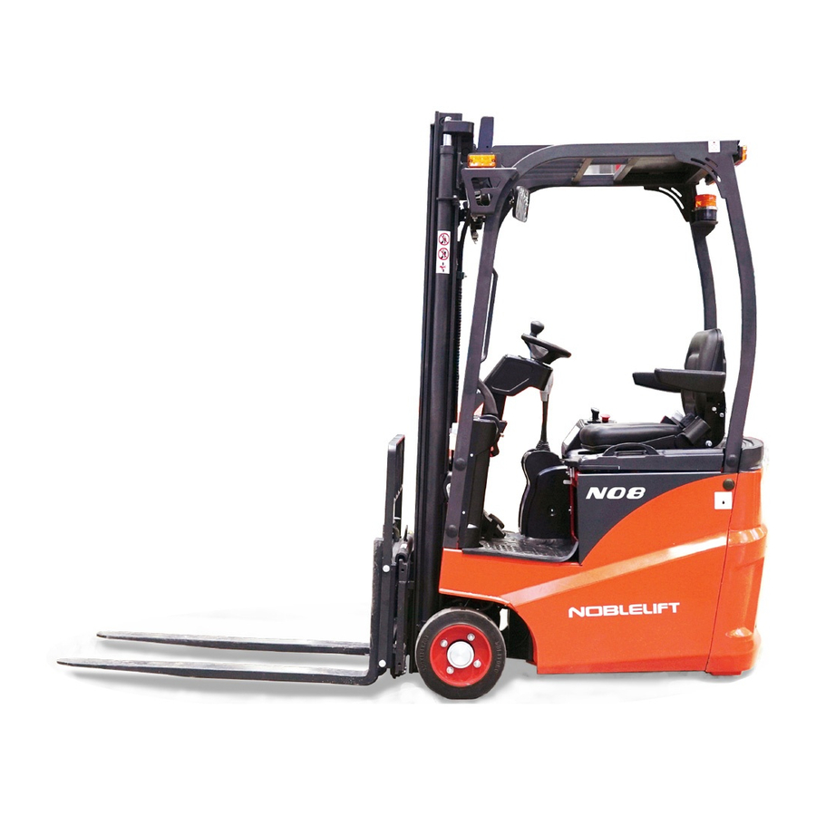
FE3R16
N/E SERIES
Battery Counterbalanced Forklift Truck
NOBLELIFT INTELLIGENT EQUIPMENT CO.,LTD.
Advertisement
Table of Contents


Need help?
Do you have a question about the N Series and is the answer not in the manual?
Questions and answers