
Related Manuals for Stinger STXKBR4


Summary of Contents for Stinger STXKBR4
- Page 1 ® 2 Channel Amplifier Wiring Kit 2021+ Ford Bronco Installation Guide STXKBR4 - 4GA STXKBR8 - 8GA StingerElectronics.com...
- Page 2 ® LIMITED WARRANTY: Stinger warrants this product to be free of defects in materials and workmanship for a period of one (1) years from the original date of purchase. This warranty is not transferable and applies only to the original purchaser from an authorized Stinger dealer in the United States of America only.
-
Page 3: Installation Notes
Installation of this product requires technical skill, experience and specialized tools. If in doubt, it’s recommended to have it professionally installed by an authorized Stinger Dealer. Designed for front driver or passenger under-seat amplifier locations. Make sure wire gauge matches amplifier power/ground inputs. -
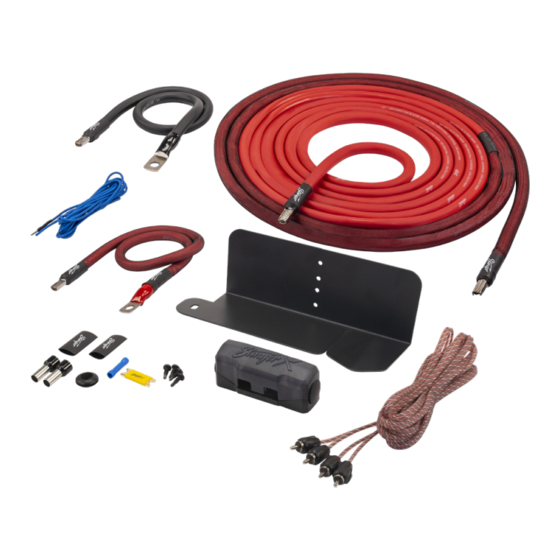
Page 4: What's In The Kit
® ® What's In The Kit ITEM DESCRIPTION Fuse to Vehicle Battery Wire (22in) Fuse to Amplifier Wire (17ft) Remote Turn-On Wire (10ft) Amplifier Ground Wire (24in) Fuse Holder Mounting Plate 2-Channel RCA Cable (12ft) Ferrules/Heat Shrink Rubber Grommet (5/8") 7"... - Page 5 StingerElectronics.com...
- Page 6 ® ® Mounting Plate and Fuse Holder Preparation 1. Remove the fuse holder 2. Using two of the supplied M3 cover and position it on the x 6mm screws, attach the fuse mounting plate as shown. holder to the mounting plate. 3.
- Page 7 6. Loosen the wire set screw 5. If installing the 4GA kit, remove on the right side and insert the the 8GA inserts (1) from both ends 22" power lead and tighten of the fuse holder by losening the securley. 4mm wire set screws.
- Page 8 ® ® Installing the Mounting Plate and Fuse Holder 1. In the engine compartment, 2. Remove the 13mm bolt and on the driver's side, locate the set aside. 13mm bolt on the inner fender between the battery and the fuse box. 3.
- Page 9 Routing the Power Wire Inside the Vehicle 1. If there are two rubber 2. Route the long end of the grommets available behind the power wire to the grommet. fuse box, use #1. Using a utility Lubricate the wire and pass it knife or diagonal cutters, cut a slit through the grommet into the in the grommet.
- Page 10 ® ® Disassembly NOTE: Disassembly is similiar for both sides of the vehicle. 1. Driver's Side Only: Using a 2. Driver's Side Only: Remove panel tool, remove the tread the two 10mm nuts securing the plate from the foot rest. foot rest to the floor.
- Page 11 5. Unclip the overlapping trim at 6. Pull the kick panel towards the the top of the kick panel. rear of the vehicle to release the remaining locking clips. 7. Pull up and release the clips on 8. Remove the rear door scuff the lower B pillar trim inside the plate by pulling upwards to front door.
- Page 12 ® ® Disassembly (cont.) 9. Pull up and release the clips on 10. Starting at the top, pull the the lower B pillar trim inside the B pillar trim towards the center rear door. of the vehicle to release the retaining clips.
- Page 13 At this point, you can remove the seat from the vehicle, or lean it all the way back out the way. NOTE! If you are going to unplug the seat wire harness, you must fully disconnect the vehicle batteries first and do not power up the vehicle with the harness unplugged.
- Page 14 ® ® In-Vehicle Wire Routing (cont.) 2. For passenger side installation, 3. Route the power wire from the pull back the carpeting on the driver's kick panel to the front of the driver's side. center console under the carpet. 4. Feed the power wire from the driver's side to the passenger side in front of the center console.
- Page 15 NOTE! The remaining steps show the Driver's side installation. The Passenger side is the same. Seat was removed for illustration purposes. 5. Pull back the carpet on the passenger side. Route the power wire to the passenger kick panel. 7. Depending on your amplifier's 6.
-
Page 16: Amplifier Wiring
® ® Amplifier Wiring 1. At the base of the B pillar, 2. Route the ground wire under attach the black ground wire the carpet from the B pillar to using the bolt indicated. Tighten the opening under the seat. securely. - Page 17 4. These are the basic connections for the amplifier. You will also need to run speaker Speaker Wire! wire (not included) to the amp Bass Knob? location. And, if the amp has a level control knob, that should also be routed to the amp mounting location.
-
Page 18: Connecting Power
® ® Amplifier Wiring (cont) NOTE: Some amplifier power terminals will not be large enough or are not designed to use ferrules. If that is the case, simply cut off the ferrule and attach the wire the old fashion way. 7. - Page 19 2. Install the ring termininal on one of the empty studs on the positve battery terminal. Secure with the M6 flange nut included in the kit. Adding an Optional Second X-Link Fuse Block The fuse mounting plate is designed to hold an optional second X-Link fuse holder.
- Page 20 ® ® Stinger is a Power Brand of AAMP Global 15500 Lightwave Drive, Suite 202 Clearwater, Florida 33760 ©2022 AAMP Global TECHNICAL SUPPORT: CUSTOMER SOLUTIONS: 727-592-5991 800-477-2267 support@stingerelectronics.com customersolutions@aampglobal.com StingerElectronics.com STXKBR-IG REV 102722...
Need help?
Do you have a question about the STXKBR4 and is the answer not in the manual?
Questions and answers