
Related Manuals for ESAB Aristo Mig 5000i 400 V


Summary of Contents for ESAB Aristo Mig 5000i 400 V
- Page 1 Mig 5000i Aristot 400 V version Instruction manual 0459 290 101 GB 060830 Valid for serial no. 620- -xxx- -xxxx...
-
Page 2: Table Of Contents
1 DIRECTIVE ............2 SAFETY . -
Page 3: Directive
DIRECTIVE DECLARATION OF CONFORMITY ESAB AB, Welding Equipment, SE--695 81 Laxå, Sweden, gives its unreserved guarantee that weld- ing power source Mig 5000i from serial number 620 complies with standard IEC/EN 60974--1, in ac- cordance with the requirements of directive (73/23/EEC) and addendum (93/68/EEC) and with stan- dard IEC/EN 60974--10 in accordance with the requirements of directive (89/336/EEC) and adden- dum (93/68/EEC). - Page 4 MALFUNCTION - - Call for expert assistance in the event of malfunction. READ AND UNDERSTAND THE INSTRUCTION MANUAL BEFORE INSTALLING OR OPERATING. PROTECT YOURSELF AND OTHERS! ESAB can provide you with all necessary welding protection and accessories. WARNING! Read and understand the instruction manual before installing or operating.
-
Page 5: Introduction
All the settings are made from the wire feed unit or control box U8. ESAB’s accessories for the product can be found on page 19. Equipment The power source is supplied complete with terminating resistor, 5 m return cable and instruction manual. -
Page 6: Installation
Mig 5000i Insulation class transformer Enclosure class IP 23 Application class Cooling unit Cooling power 2500 W at 40˚C temp. difference and flow1.5l/min Coolant 50 % water / 50% glycol Coolant quantity 5.5 l Maximum water flow 2.0 l/min Maximum number of water--cooled welding two MIG welding guns or guns/torches that may be connected one TIG torch and one MIG welding gun... -
Page 7: Lifting Instructions
Lifting instructions Power source Trolley and power source Trolley2 and power source Placing Position the welding power source such that its cooling air inlets and outlets are not obstructed. Mains power supply Check that the unit is connected to the correct mains power supply voltage, and that it is protected by the correct fuse sizes. -
Page 8: Terminating Resistor
Terminating resistor In order to avoid communication interference, the ends of the CAN bus must be fitted with terminating resistors. One end of the CAN bus is at the control panel, which has an integral terminating resistor. The other end at the power source must be fitted with the terminating resistor, as shown on the right. - Page 9 Two wire feed units A connection kit is required when connecting two wire feed units, see accessories on page 19. Four wire feed units Two connection kits and an extra cooling unit are required when connecting four wire feed units, see accessories on page 19. - - 9 - - ba37d1ea...
-
Page 10: Operation
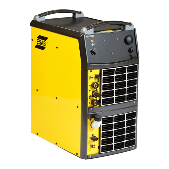
OPERATION General safety regulations for the handling of the equipment can be found on page 3. Read through before you start using the equipment! Connections and control devices Connection for cooling water. Not used on White indicating lamp -- Power supply ON this model. -
Page 11: Fan Control
Fan control The power source fans continue to run for 6,5 minutes after welding has stopped, and the unit switches to energy--saving mode. They start again when welding restarts. The fans run at reduced speed for welding currents up to 180 A, and at full speed for higher currents. -
Page 12: Maintenance
MAINTENANCE Regular maintenance is important for safe, reliable operation. Maintenance must be executed by a professional. Only those persons who have appropriate electrical knowledge (authorized personnel) may remove the safety plates. Note! All guarantee undertakings from the supplier cease to apply if the customer himself attempts any work in the product during the guarantee period in order to rectify any faults. -
Page 13: Fault Tracing
Repair and electrical work should be performed by an authorized ESAB serviceman. Use only ESAB original spare and wear parts. Spare parts may be ordered through your nearest ESAB dealer, see the last page of this publication. - - 13 - -... -
Page 14: Diagram
Diagram - - 14 - - ba37e11a... - Page 15 - - 15 - - ba37e11a...
- Page 16 Cooling unit - - 16 - - ba37e11a...
-
Page 17: Ordering Number
Mig 5000i 0459 230 881 Welding power source Mig 5000i with cooling unit 0459 290 990 Spare part list Mig 5000i The spare parts list is available on the Internet at www.esab.com - - 17 - - Edition 060830 ba37o11a... -
Page 18: Spare Parts List
Mig 5000i Spare parts list Item Ordering no. Denomination 0458 398 001 Filter 0458 383 001 Front grill - - 18 - - Edition 060830 ba37s... -
Page 19: Accessories
Mig 5000i Accessories Trolley ....... . . 0458 530 880 Trolley 2 (for feeder with counterbalance device and/or 2 gas bottles) . - Page 20 Mig 5000i Feeder stand ......0458 522 880 Remote control adapter RA12 12 pole ..0459 491 910 For analogue remote controls to CAN based equipment.
- Page 21 Mig 5000i Remote control cable 12 pole - - 4 pole 5 m ........0459 554 880 10 m .
- Page 22 Mig 5000i Connection set for connection of two wire feed units ..0459 546 880 Cooling unit OCE2H ....0414 191 881 - - 22 - - R0459 290/E060830/P24 ba37a11a...
- Page 23 - - 23 - -...
- Page 24 ESAB subsidiaries and representative offices Europe Asia/Pacific Representative offices NORWAY AS ESAB AUSTRIA BULGARIA CHINA Larvik ESAB Ges.m.b.H ESAB Representative Office Shanghai ESAB A/P Tel: +47 33 12 10 00 Vienna- -Liesing Sofia Shanghai Fax: +47 33 11 52 03...
Need help?
Do you have a question about the Aristo Mig 5000i 400 V and is the answer not in the manual?
Questions and answers