
Related Manuals for Satel PERFECTA-IP-32


Summary of Contents for Satel PERFECTA-IP-32
- Page 1 INSTALLER MANUAL perfecta-ip_i_en 07/20 SATEL sp. z o.o. ul. Budowlanych 66 • 80-298 Gdańsk • POLAND tel. +48 58 320 94 00 www.satel.eu...
- Page 2 Changes, modifications or repairs not authorized by the manufacturer shall void your rights under the warranty. SATEL aims to continually improve the quality of its products, which may result in changes in their technical specifications and software. Current information about the changes being introduced is available on our website.
-
Page 3: Table Of Contents
CONTENTS 1. Introduction ........................2 2. Features..........................2 3. Keypads..........................4 Keypads features ........................4 4. Expansion modules ......................4 5. MICRA wireless devices PERFECTA-IP 32-WRL ............5 6. System installation ......................5 Installation plan ........................5 Estimation of the system current consumption ................ 6 Cabling ............................. -
Page 4: Introduction
• Capability to connect keypads and expansion modules. • Electrical protection of communication bus. Wireless devices only PERFECTA-IP 32-WRL • Support for 433 MHz radio devices manufactured by SATEL: – up to 32 detectors, – up to 4 sirens, – up to 4 keypads, –... - Page 5 SATEL PERFECTA-IP • Up to 6 control functions available from keyfob. Communication • Built-in Ethernet module. Reporting • Reporting events to two monitoring stations. • Support for Contact ID and SIA communication formats. • Sending event codes to the monitoring station via Ethernet.
-
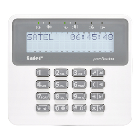
Page 6: Keypads
PERFECTA-IP SATEL 3. Keypads Fig. 1. PRF-LCD / PRF-LCD-WRL keypad. SATEL offers the following keypads for PERFECTA-IP alarm control panels: PRF-LCD – hardwired LCD keypad with mechanical keys, PRF-LCD-WRL – wireless keypad with mechanical keys (supported PERFECTA-IP 32-WRL control panel). -
Page 7: Micra Wireless Devices Perfecta-Ip 32-Wrl
SATEL PERFECTA-IP 5. MICRA wireless devices PERFECTA-IP 32-WRL The PERFECTA-IP 32-WRL control panel supports the following MICRA (433 MHz) wireless devices: MFD-300 – wireless water flood detector. MGD-300 – wireless glass-break detector. MMD-300 – wireless magnetic contact. MMD-302 – wireless magnetic contact with input for roller shutter detector. -
Page 8: Estimation Of The System Current Consumption
PERFECTA-IP SATEL When planning the installation location for the PERFECTA-IP 32-WRL control panel and MICRA wireless devices, you must take into consideration the range of radio communication. Remember that thick walls, metal partitions, etc. will reduce the range of the radio signal. -
Page 9: Description Of The Mainboards
SATEL PERFECTA-IP 6.4.1 Description of the mainboards Fig. 2. Mainboard of the control panel. LED indicators: left – not used. center – ON when the battery is being tested. right – not used. RESET pins for emergency starting the control panel (see: “Emergency procedure of the control panel start-up”... -
Page 10: Connecting Devices To The Communication Bus
PERFECTA-IP SATEL +OUT1-, +OUT2- - programmable high-current outputs. +12 VDC voltage is always present at the “+” terminal. The “–” terminal is either shorted to or disconnected from common ground, depending output status (active/inactive) and polarity. OUT3, OUT4 - programmable low-current outputs, OC type (disconnected from common ground / shorted to common ground). - Page 11 SATEL PERFECTA-IP Fig. 3. Opening the keypad enclosure. 2. Put the enclosure base on the wall and mark the location of mounting holes. 3. Drill the holes in the wall for wall plugs (screw anchors). 4. Run wires through the opening in the enclosure base.
-
Page 12: Perfecta-Ip 32
PERFECTA-IP SATEL Fig. 4. Connecting keypad to the control panel. 6.5.2 Connecting 433 MHz keyfobs receiver expansion module PERFECTA-IP 32 You can connect the INT-RX-S expansion module to the PERFECTA-IP 32 control panel. The module enables 433 MHz keyfobs to be assigned to the users (up to 15 keyfobs). - Page 13 SATEL PERFECTA-IP Fig. 7. Connecting the INT-E expander to the control panel. Address 12 (0Ch), 13 (0Dh) or 14 (0Eh) must be set in the zone expander. The DIP-switch 10 must be set to the OFF position. Fig. 8. Setting the DIP-switches in the INT-E expander.
-
Page 14: Connecting The Hardwired Output Expander
PERFECTA-IP SATEL 6.5.4 Connecting the hardwired output expander You can connect the INT-O or INT-ORS expander to the control panel. This enables expansion of the system by adding 8 programmable wired outputs. Address 15 (0Fh) must be set in the expander. In the case of the INT-ORS expander, the DIP-switch 10 must be set to the ON position. - Page 15 SATEL PERFECTA-IP 2EOL/NC – wiring configuration that is recommended when connecting a detector with NC alarm output and tamper output. Two EOL resistors must be used in the circuit. The zone can distinguish between 3 states: normal, alarm and tamper.
- Page 16 PERFECTA-IP SATEL PERFECTA-IP Fig. 13. Example of connecting an NC detector (NO detector connect in the same way). PERFECTA-IP Fig. 14. Example of connecting an NC detector in Single EOL configuration.
-
Page 17: Connecting The Sirens
SATEL PERFECTA-IP PERFECTA-IP Fig. 15. Example of connecting an NO detector in Single EOL configuration. PERFECTA-IP Fig. 16. Example of connecting an NC detector in Double EOL (2EOL) configuration (NO detector connect in the same way). End-of-line resistors For the Single EOL configuration, use a 2.2 kΩ resistor to close the circuit. For the Double EOL (2EOL) configuration, use two 1.1 kΩ... -
Page 18: Connecting The Ethernet Network
PERFECTA-IP SATEL Depending on the siren type: • sirens without own power supply (e.g. SP-500, SP-4001, SP-4003, SPL-2010, SPW-100, SPW-210, SPW-220) – high-current outputs are to be used to trigger the signaling, • sirens with own power supply (e.g. SP-4002, SP-4004, SP-4006, SP-6500, SPLZ-1011, SD-3001, SD-6000) –... -
Page 19: Backup Power Supply
SATEL PERFECTA-IP Do not connect two devices with power supply to one-section transformer. Before connecting transformer to a circuit from which it will be powered, make sure the circuit is de-energized. 6.9.2 Backup power supply A 12 V lead-acid sealed battery should be connected to the control panel as a backup power source. -
Page 20: Emergency Procedure Of The Control Panel Start-Up
PERFECTA-IP SATEL 4. When the cursor shows the S function, press ERVICE MODE 5. Service mode menu will be displayed (the cursor will show the E SM function). 6.9.5 Emergency procedure of the control panel start-up If the control panel fails to start properly, keypads are not supported, codes are not accepted by the control panel etc., despite all connections having been made correctly, follow the steps... -
Page 21: Programming The Address By Means Of The Service Function
SATEL PERFECTA-IP 6.10.1 Programming the address by means of the service function The address programming function can be started from either a wired or wireless keypad, but it will only allow setting addresses in the wired keypads. 1. Start the service mode (see: “Starting the service mode” p. 17). -
Page 22: Starting The Identification Function From Perfecta Soft Program
6.12 Connecting the computer to the control panel You can connect the control panel RS-232 (TTL) port with the USB port on a computer. To make the connection, use the USB-RS converter offered by SATEL. Having connected the computer to the control panel, you can: •... -
Page 23: Adding New Wireless Devices
SATEL PERFECTA-IP 6.13.1 Adding new wireless devices If you want to add the MRU-300 repeater, proceed in the same way as when adding a wireless detector. PERFECTA S program Adding wireless keypad 1. Click on the “Hardware” tab. 2. Click on one of the unused keypads. Address of this keypad will be assigned to the wireless keypad after the adding procedure is finished. -
Page 24: Removing Wireless Devices
PERFECTA-IP SATEL 2. Press successively to run the 1271.A function. 3. Enter the serial number of the wireless device. You will find it on the electronics board or enclosure of the device. 4. Press 5. When the “Open tamper device” command is displayed, −... -
Page 25: Numeration Of Zones And Outputs In The System
SATEL PERFECTA-IP 5. Click to save changes to the control panel. Keypad 1. Start the service mode (see “Starting the service mode” p. 17). 2. Press successively to run the 1273.R function. EMOVE 3. Use the keys to select: − when removing a keypad: the keypad you want to remove, −... - Page 26 PERFECTA-IP SATEL Standby current consumption PERFECTA-IP 32 ..............100 mA PERFECTA-IP 32-WRL ............120 mA Maximum current consumption PERFECTA-IP 32 ..............200 mA PERFECTA-IP 32-WRL ............220 mA Standby current consumption from battery PERFECTA-IP 32 ..............110 mA PERFECTA-IP 32-WRL ............130 mA Maximum current consumption from battery PERFECTA-IP 32 ..............
-
Page 27: Prf-Lcd Keypad
SATEL PERFECTA-IP PERFECTA-IP 32-WRL ............118 g PRF-LCD keypad Supply voltage ....................12 VDC ±15% Standby current consumption ..................30 mA Maximum current consumption ..................50 mA Environmental class according to EN 50130-5 ................ II Operating temperature range .................. -10…+55°C Maximum humidity ......................
Need help?
Do you have a question about the PERFECTA-IP-32 and is the answer not in the manual?
Questions and answers