
Related Manuals for Satel PERFECTA-T


Summary of Contents for Satel PERFECTA-T
- Page 1 INSTALLER MANUAL SATEL sp. z o.o. ul. Budowlanych 66 80-298 Gdańsk POLAND tel. +48 58 320 94 00 www.satel.eu perfecta-t_i_en 11/18...
- Page 2 Changes, modifications or repairs not authorized by the manufacturer shall void your rights under the warranty. SATEL's goal is to continually upgrade the quality of its products, which may result in some changes of their technical specifications and firmware. The current information on the introduced modifications is available on our website.
-
Page 3: Table Of Contents
Description of the mainboard ......................7 Connecting devices to the communication bus................ 8 6.5.1 Connecting keypads........................8 6.5.2 Connecting 433 MHz keyfobs receiver expansion module PERFECTA-T 32 ......10 6.5.3 Connecting the hardwired zone expanders................10 6.5.4 Connecting the hardwired output expander ................12 Connecting detectors and other devices to the zones ............12 Connecting the sirens ...................... -
Page 4: Introduction
PERFECTA-T SATEL 1. Introduction This manual describes the PERFECTA-T 32 and PERFECTA-T 32-WRL control panels and how to install them. In addition, the manual provides information about devices compatible with the control panel and how they are to be connected. -
Page 5: Voice Messages
SATEL PERFECTA-T Communication Built-in analog telephone communicator. Reporting Reporting events to two monitoring stations. Support for Contact ID and SIA communication formats. Messaging Event notification to 8 phone numbers in the form of 16 voice messages. -
Page 6: Keypads
PERFECTA-T SATEL 3. Keypads Fig. 1. PRF-LCD / PRF-LCD-WRL keypad. SATEL offers the following keypads for PERFECTA alarm control panels: PRF-LCD – hardwired LCD keypad with mechanical keys, – wireless keypad with mechanical keys (supported PRF-LCD-WRL PERFECTA-T 32-WRL control panel). -
Page 7: Wireless Devices Perfecta-T 32-Wrl
SATEL PERFECTA-T 5. Wireless devices PERFECTA-T 32-WRL The PERFECTA-T 32-WRL control panel supports the following 433 MHz wireless devices: MFD-300 – wireless water flood detector. MGD-300 – wireless glass-break detector. MMD-300 – wireless magnetic contact. MMD-302 – wireless magnetic contact with input for roller shutter detector. -
Page 8: Installation Of Control Panel
PERFECTA-T SATEL If you use the twisted-pair type of cable, remember that CLK (clock) and DTA (data) signals must not be sent through one pair of twisted conductors. Select cross-section of the power supply wires so that the supply voltage drop between the power supply and the supplied device should not exceed 1 V as against the output voltage. -
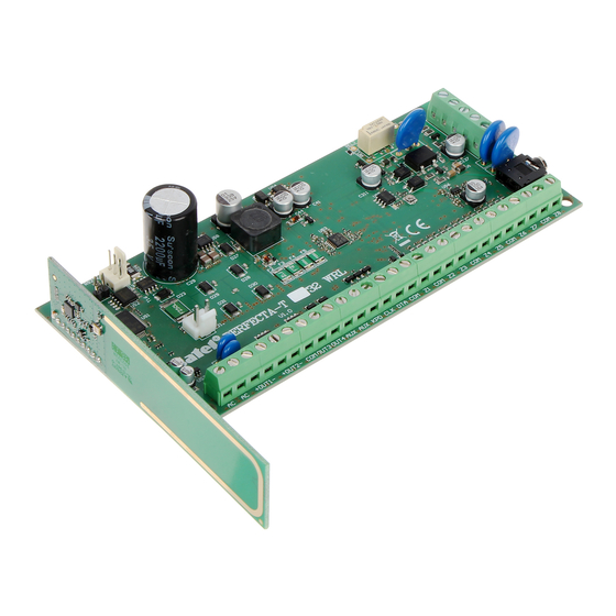
Page 9: Description Of The Mainboard
RS-232 (TTL) port. battery connection cables (red +, black -). LED indicating the status of control panel telephone communicator. wireless system module. only PERFECTA-T 32-WRL mini-jack socket for connecting microphone. Description of terminals: - power input (18 V AC). +OUT1-, +OUT2- - programmable high-current outputs. +12 V DC voltage is always present at the “+”... -
Page 10: Connecting Devices To The Communication Bus
PERFECTA-T SATEL - programmable low-current outputs, OC type (disconnected from OUT3, OUT4 common ground / shorted to common ground). - common ground. - +12 V DC power output. - +12 V DC power output. - communication bus data. - communication bus clock. - Page 11 SATEL PERFECTA-T Fig. 3. Opening the keypad enclosure. 2. Put the enclosure base on the wall and mark the location of mounting holes. 3. Drill the holes in the wall for wall plugs (screw anchors). 4. Run wires through the opening in the enclosure base.
-
Page 12: Perfecta-T 32
6.5.2 Connecting 433 MHz keyfobs receiver expansion module PERFECTA-T 32 You can connect the INT-RX-S expansion module to the PERFECTA-T 32 control panel. The module enables 433 MHz keyfobs to be assigned to the users (up to 15 keyfobs). Address 7 (07h) must be set in the module. - Page 13 SATEL PERFECTA-T Fig. 7. Connecting the INT-E expander to the control panel. Address 12 (0Ch), 13 (0Dh) or 14 (0Eh) must be set in the zone expander. The DIP-switch 10 must be set to the OFF position. Fig. 8. Setting the DIP-switches in the INT-E expander.
-
Page 14: Connecting The Hardwired Output Expander
PERFECTA-T SATEL 6.5.4 Connecting the hardwired output expander You can connect the INT-O or INT-ORS expander to the control panel. This enables expansion of the system by adding 8 programmable wired outputs. Address 15 (0Fh) must be set in the expander. In the case of the INT-ORS expander, the DIP-switch 10 must be set to the ON position. -
Page 15: Connecting The Sirens
SATEL PERFECTA-T 2EOL/NC – wiring configuration that is recommended when connecting a detector with NC alarm output and tamper output. Two EOL resistors must be used in the circuit. The zone can distinguish between 3 states: normal, alarm and tamper. -
Page 16: Connecting The Microphone
The microphone will allow the users to listen in to the sounds from the protected premises after establishing telephone connection with the control panel. SATEL offers the MIC-1 microphone, which can be connected to the mini-jack socket on the control panel. If you decide to use another type, it should be an electret microphone, e.g. -
Page 17: Connecting The Power Supply And Starting The Control Panel
SATEL PERFECTA-T If the ADSL service is used on the premises where the control panel is installed, the control panel should be connected after the ADSL filter, and the other devices using the analog telephone line should be connected to the control panel. -
Page 18: Control Panel Power-Up / Start-Up Procedure
PERFECTA-T SATEL Do not connect deeply discharged battery to the control panel (with voltage across unloaded terminals below 11 V). The battery should be precharged with a proper charger. The used batteries must not be discarded, but should be disposed of in accordance with the existing rules for environment protection. -
Page 19: First Steps After Starting-Up The Control Panel
SATEL PERFECTA-T 4. Wait a few seconds (until LEDs next to the RESET pins stop blinking) and remove the jumper from the RESET pins. The control panel will enter the service mode. The service mode menu will be displayed on the wired keypad with the lowest address. -
Page 20: Programming The Address Without Entering The Service Mode
PERFECTA-T SATEL Fig. 15. Programming keypad address (n = current address). 4. On the keypad the address of which you want to change, press the key whose digit corresponds to the new address. 5. Press to finish the function (the function will be finished automatically after 2 minutes since it was launched). -
Page 21: Starting The Identification Function From Perfecta Soft Program
6.13 Connecting the computer to the control panel You can connect the control panel RS-232 (TTL) port with the USB port on a computer. To make the connection, use the USB-RS converter offered by SATEL. Having connected the computer to the control panel, you can: ... - Page 22 PERFECTA-T SATEL 5. In the “Serial no.” field, enter the serial number of the keypad. You will find it on the keypad electronics board. 6. Press any key on the keypad being added. 7. When the “Device's data read” message appears, click “OK”.
-
Page 23: Removing Wireless Devices
SATEL PERFECTA-T 8. When the “SELECT...” command is displayed, use the keys to select: when adding a keypad: the address to be assigned to the keypad, when adding a detector: the zone to which the detector is to be assigned, ... -
Page 24: Numeration Of Zones And Outputs In The System
Supply voltage ................... 18 V AC ±15%, 50-60 Hz Recommended transforme r ..................... 40 VA Standby current consumpt PERF ECTA-T 32 ..............100 mA PERFECTA-T 32-WRL ............130 mA Maximum current consump tion PERFECTA-T 32 ..............160 mA PERFECTA-T 32-WRL ............190 mA Standby current consumpt ion from battery PERFECTA-T 32 ..............90... -
Page 25: Prf-Lcd Keypad
Operating temperature ran ge................. -10…+55 °C Maximum humidity ......................93±3% Electronics board dimensio PERFECTA-T 32 ............160 x 68 mm PERFECTA-T 32-WRL ..........160 x 110 mm Weight PERFECTA-T 32 ..............100 g PERFECTA-T 32-WRL ............110 g PRF-LCD keypad Supply voltage .................... - Page 26 PERFECTA-T SATEL Enclosure dimensions ................. 139 x 124 x 22 mm Weight..........................246 g...
Need help?
Do you have a question about the PERFECTA-T and is the answer not in the manual?
Questions and answers