
Related Manuals for Carrier EverFRESH


Summary of Contents for Carrier EverFRESH
- Page 1 Container Refrigeration OPERATIONS, SERVICE AND PARTS MANUAL EverFRESH® Controlled Atmosphere Option T-374 Rev E...
- Page 3 OPERATIONS, SERVICE AND PARTS MANUAL EverFRESH® Controlled Atmosphere Option © Carrier Corporation, 2023 Printed in U. S. A. April 2023...
-
Page 5: Table Of Contents
3–1 EVERFRESH AIR AND GAS FLOW .......... - Page 6 ........5–22 5.5.1 Removing the EverFRESH Nitrogen Valve ......5–22 SENSOR ASSEMBLY .
- Page 7 2–4 Figure 3.1 EverFRESH Air and Gas Flow Diagram ..........
- Page 8 5–1 Table 5–2 EverFRESH Function Codes ........... . .
-
Page 9: Safety Summary
CAUTION - alert to potential hazard or unsafe practice that could result in minor personal injury, product or property damage. The following safety statements are applicable to the EverFRESH option unit used with any container unit and appear elsewhere in this manual. These recommended precautions must be understood and applied during operation and maintenance of the equipment covered herein. - Page 10 CAUTION Do not run the Calibration tests under loaded conditions. While the EverFRESH option is operating, the process of inducing ripening by introducing eth- ylene should not be performed. It is required that the calibration procedure only be performed during Pre-Trip or when the con- tainer has been fully vented.
-
Page 11: Introduction
(Figure 2.1). The air compressor for EverFRESH is located below the condenser behind a splash guard. A manually operated venting system is located in the upper left access panel. The panel may be removed to allow entry into the evaporator section where the atmosphere sensors, control valves, water separator and air filters are located. -
Page 12: Figure 2.2 Refrigeration Unit - Evaporator Section (Upper Panel Removed)
Other than the air compressor, all of the components of the EverFRESH option are mounted in the evaporator 2.2) in addition to the standard refrigeration unit components. section (Figure Figure 2.2 Refrigeration Unit - Evaporator Section (Upper Panel Removed) EverFRESH components located in evaporator section 2.3) include the water separator, particulate filters, Water Drain Valve (WDV), Nitrogen... -
Page 13: Figure 2.3 Everfresh Components
1) Air Compressor 9) Nitrogen Supply Orifice 2) Condensing Loop 10) Nitrogen Sampling Orifice 3) Water Separator 11) EverFRESH Nitrogen Valve (EN) 4) Particulate Filters (2) 12) Cargo Air Sensor Inlet 5) Water Drain Valve (WDV) 13) Cargo Air Sensor Filter Assembly... -
Page 14: Optional Co2 Injection System
Optional CO2 Injection System There is an optional CO2 injection kit that can be added to the system that allows CO2 to be actively injected into the cargo space during transport. In this configuration, a CO bottle is used with a regulator to maintain an input pressure of 50 psig, not to exceed 100 psig. -
Page 15: System Data
System Data Table 2–1 System Data Component Data Detail Air Compressor Number of Cylinders Type Three Phase Induction Weight 44 lbs Full Load Amps 1.34 amps 50Hz / 1.4 amps 60Hz. Voltage and Frequency 360 - 460 VAC 50 Hz +/-2.5Hz 400 - 500 VAC 60Hz +/-2.5 Hz Speed 1425/50 Hz 1725/60Hz RPM... -
Page 17: Operation
O2 levels from dropping below the lower setpoint. A CO2 sensor provides CO2 levels to the controller to allow the control algorithm to activate the required EverFRESH components. For low respiring cargoes requiring high CO2 setpoints, an optional CO2 Injection system can be used to maintain CO2 levels. -
Page 18: Figure 3.1 Everfresh Air And Gas Flow Diagram
The Nitrogen Sampling orifice regulates the flow of nitrogen to the EverFRESH Nitrogen Valve (EN). The controller will open EN to allow the gas to flow into the sensor package for testing at the O2 Sensor. Elevated amounts of oxygen indicate the Nitrogen Membrane may be clogged. The EN is only energized during Pre-trip test P20-5 N2 Check. -
Page 19: Pre-Trip Inspection
Pre-Trip Inspection An EverFRESH Pre-Trip Inspection (PTI) is required to run prior to cargo being loaded in order to test operation of mechanical components and calibrate the sensors. A PTI must only be performed with a well vented container box. - Page 20 Then re-run the Pre-trip “AutCA” test under the PRE-TRIP key menu. P20-5 EverFRESH Nitrogen Valve (EN) Solenoid Test Test Sequence: Test will start with EAC off. Energize EN and wait 5 seconds. Energize EAC. Test will run up to an additional 300 seconds or until N2 reaches acceptable limit. Then the EAC and EN will be de-energized.
-
Page 21: Enabling Everfresh Operation
Enabling EverFRESH Operation EverFRESH is activated via function code Cd71. This code allows the user to select a specific mode of operation and the associated parameters. The modes of operation are: FrESh, OFF, and PUrgE. Within each of these modes of operation are sub menus that have selectable parameters. -
Page 22: Activate Or Deactivate Purge Mode
When Purge mode is active, it allows the user to suspend EverFRESH operations while pre-charging gas levels in the container. All EverFRESH control actions and alarm 929 is suspended in order to purge the container to a desired gas concentration. When activated, Purge mode stays active for a period of time selected from the Purge mode sub menu. -
Page 23: Co2 Injection Mode (Cd76)
3. Use the Arrow keys to toggle between “On” and “OFF” and press ENTER to confirm the selection. 3.5.5 Code 44 (Cd44) Cd44 allows the user to view the following EverFRESH values: CO2 setpoint, CO2 percentage, O2 setpoint, O2 percentage, O2 voltage and Membrane Pressure Transducer (MPT) pressure. 3.5.6 Display Cd44 Values 1. -
Page 24: Container Venting Procedure
Container Venting Procedure WARNING Potential hazardous atmosphere and low oxygen levels may exist inside the container. Venti- late before entering. Stay away from doors and access panels while venting. 1. Set the Start-Stop (ST) switch to the “I” position to turn the unit On. 2. -
Page 25: Troubleshooting
Manual Fresh Air Vent Open Cause: For units equipped with EverFRESH and a Vent Position Sensor (VPS), the controller will monitor the manual fresh air opening at a pre-determined time. If during this time the manual fresh air vent is open and EverFRESH is active, an alarm will be generated. - Page 26 Cause: Triggered anytime the CO2 sensor reading is outside of the normal operation range, after an initial signal was detected. Action: EverFRESH Air Compressor (EAC) 100% duty cycle and open the EverFRESH Air Valve (EA). Will prevent low O2 and cargo loss. If both AL909 and AL910 are active, run the EAC and open the EA.
- Page 27 Troubleshooting Seal container where possible (access panels, rear doors, mounting hardware, etc). AL976 Air Compressor Internal Protector Open Cause: EverFRESH Air Compressor (EAC) internal protector opens. Component EverFRESH Air Compressor (EAC) Troubleshooting Follow steps defined in AL929 EAC testing. Component ML5 Controller Troubleshooting Access function code Cd74 to perform an ML5 self-diagnostic test.
- Page 28 Membrane Pressure Transducer (MPT) Fault Cause: When the EverFRESH Air Compressor (EAC) is running and pressure is not between -5 psig and 200 psig or the EAC has been OFF for five minutes and pressure is not within the range of -5 psig and 5 psig.
- Page 29 AL980 Fresh Air Valve (EA) Fault Cause: When the system energizes the EverFRESH Air Valve (EA) solenoid and membrane pressure does not drop 40 psi, the alarm is triggered. The alarm triggers OFF when membrane pressure transducer (MPT) pressure drop is more than 40 psi when EA is opened.
-
Page 30: Everfresh Troubleshooting
EverFRESH Troubleshooting This troubleshooting section is for the EverFRESH option only. Prior to testing the EverFRESH unit, verify that the refrigeration system is functioning properly. Table 4–2 Troubleshooting System Conditions Condition Possible Causes Recommended Actions EverFRESH Air Compressor EAC contactor not engaging... - Page 31 Container box not sealed Perform pressure decay test. Leaky cylinder head Perform minor rebuild. EverFRESH Air Compressor EverFRESH Air Valve (EA) does not Check F3 fuse. (EAC) Runs But O2 Does open Not Come Up Run a P20 PTI test. P20-2 will check for proper valve operation: electrical and mechanical.
-
Page 33: Service
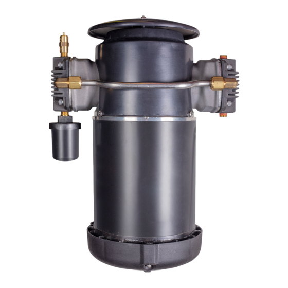
Note: Replace a sticker with date when making a filter change. 5000 Hours Perform minor rebuild of air compressor. Section 5.2.5 EverFRESH Air Compressor (EAC) Service Refer to Warnings in the beginning of this Service section before performing maintenance. 2.1) is an oil-less, two cylinder compressor mounted on the front of the unit next to the... -
Page 34: Air Compressor Function Codes
Cd73 Air Compressor Total Operational Hours Cd73 displays the total number of operational hours for the EverFRESH system and air compressor. The total hours are displayed in increments in 10 hours (i.e. 3000 hours will be displayed as 300). The sub menus in this function code are “ACHrt” and “ReSEt”: “ACHrt”... -
Page 35: Removing The Air Compressor
3. Clean any debris out of the filter housing. 4. Install the new felt filter and then replace the filter cap by pressing up into the slot and turn a 1/4 turn clock- wise to lock. 5.2.3 Removing the Air Compressor 1. - Page 36 3. Using a 5/8” wrench, remove the air compressor discharge line. 4. Using a 9/16” socket, remove the eight bolts securing the air compressor mounting bracket to the container frame. 5. Pull the air compressor with the bracket away from the container frame to complete removal. 5.2.4 Installing the Air Compressor 1.
-
Page 37: Air Compressor Minor Rebuild
2. Install the remaining seven bracket bolts and then torque to 30 to 35 ft-lbs. (41 to 47 Nm). 3. Install the discharge line. Tighten with a 5/8” wrench and then torque to 23 in-lbs. (2.6 Nm). 4. Connect the air compressor power connection and wire tie the harness to the drain line and yellow power cable. - Page 38 Procedure for Disassembly 1. Remove eight phillips screws from the protective shield. Remove the shield. The fan is not part of a minor rebuild so use caution not to damage. 2. Loosen the two crossover pipe compression nuts for one of the heads using a 3/4” wrench. 3.
- Page 39 4. Remove crossbars from the air compressor using a 3/4” wrench. 5. Remove the cylinder from the air compressor by removing the 2 - 3/16” hex bolts and pulling off the piston. Use caution not to damage the fan. Discard bolts, do not reuse. 6.
- Page 40 9. Remove the old gasket material from the cylinder head and cylinder using a gasket removal tool. Ensure all parts are clean and free of debris. Procedure for Reassembly 1. Install silver rings on the piston first. 2. Install the black ring over the silver ring on the piston. Open slightly to get over the piston and slide into place.
- Page 41 Use a straight edge to check that it is flush with the top of the cylinder. 4. Lay the head upside down on a bench. Take the gasket with the material in the middle and place it on the head lettering up and align with the separation in the head and indicator hole. 5.
- Page 42 6. Install the new valve plate by aligning the indicator hole on the plate to the discharge valve. When properly installed, two holes will cover the discharge valve and two holes the head is visible. If you cannot see the head on two adjacent holes, the backer plate is not installed properly.
-
Page 43: Air Compressor Major Rebuild
11. Replace the protective cover. Use thread locker on the eight screws holding the cover in place. 12. Reinstall the air compressor into the system. 13. Run the compressor for 10 minutes by setting the CO2 and O2 setpoints to 5% and turn on the EverFRESH option in Cd71. - Page 44 Procedure for Disassembly 1. Remove eight phillips screws from the protective shield. Remove the shield. 2. Loosen the two crossover bar compression nuts for one of the heads using a 3/4” wrench. 3. Remove the head with loosened crossbar nuts using a 3/16” hex key. Remove the four head bolts and pull off the head assembly including valve plates.
- Page 45 5. Remove the cylinder from the air compressor by removing the 2 - 3/16” hex bolts and pulling off the piston. Use caution not to damage the fan. Discard all components except for the crossbar. 6. Remove the piston guide and rings from the piston and discard. 7.
-
Page 46: Filter Assembly
10. Remove the c-clip from the shaft. This is not required for rebuild and can be discarded. 11. Slide the connecting rod removal tool (part # 07-00579-00) behind the connecting rod. Have the angled edge towards the motor. Rotate the tool so the open slot is parallel to the connecting rod. 12. -
Page 47: Removing The Water Separator And Water Drain Valve
EverFRESH access panel door. 2. Cut the tie on the Vent Position Sensor (VPS) wiring to relieve tension. Unplug the VPS if installed and remove the access panel. - Page 48 4. Remove the cushion clamp from the Water Separator bowl. 5. Pull down the locking clamp and turn a 1/4 turn clockwise, and drop the Water Separator bowl. 6. Disconnect the air line and remove the complete assembly. T-374 5–16...
- Page 49 7. Remove the Water Drain Valve (WDV) from the manifold. Check the inlet for any debris and, if present, col- lect a sample. Blow out the WDV with shop air and set aside to reinstall after the Water Separator is inspected.
-
Page 50: Replacing The Particulate Air Filters
EverFRESH access panel door. 2. Remove both filter housings by turning counterclockwise until free. Carefully lay down each housing to pre- vent damage to evaporator fins. - Page 51 3. Remove the first filter by rotating the filter counterclockwise. Once removed, install the new filter by rotating clockwise. 4. Remove the second filter from the filter housing by pressing up on the locking tab holding the filter in place. 5.
-
Page 52: Everfresh Air Valve (Ea)
5.2) maintains the desired oxygen levels inside the cargo space. When the controller detects that oxygen levels are dropping below the threshold setting, it will open the EA valve to force the clean, dry, pressurized, air into the cargo space. Figure 5.2 EverFRESH Air Valve (EA) T-374 5–20... -
Page 53: Removing The Everfresh Air Valve
Removing the EverFRESH Air Valve NOTE Make note of the direction arrow on the valve body to ensure proper direction of flow. 1. Open the panel needed to gain access to the EverFRESH Air Valve (EA) (Figure 5.2). This component can be accessed from the front of the unit through the upper left access panel, or from inside the container through the EverFRESH access panel door. -
Page 54: Everfresh Nitrogen Valve (En)
EA coil. Removing the evaporator fan motor will allow for more space but not neces- sary. When removing from the back of the unit through the EverFRESH access panel, access to the compo- nents is easier. -
Page 55: Sensor Assembly
5.4) consists of an air filter, O2 sensor and CO2 sensor. The O2 sensor monitors O2 levels and allows the system to prevent O2 levels from dropping below the lower setpoint. A CO2 sensor provides CO2 levels to the controller to allow the control algorithm to activate the required EverFRESH components. Figure 5.4 Sensor Assembly... -
Page 56: Replacing The Sensor Air Filter Element
EverFRESH access panel door. 3. Unscrew and remove the filter cup from the bottom of the sensor air filter assembly. -
Page 57: Identifying And Replacing Orifices
(Figure fan deck between the evaporator fan motors. Refer to Figure 2.3 for location of the orifices in relation to all of the EverFRESH components. Refer to Warnings in the beginning of this Service section before performing maintenance. Figure 5.5 Nitrogen Supply and Nitrogen Sampling Orifices 5.8.1... -
Page 59: Everfresh And Container Pre-Trip Preparation
Box Checkout / Leak Test When using the EverFRESH system, the box must conform to leak rates in order to maintain control of the O2 and CO2 setpoints. The minimal box requirement is a pressure decay of 2 inch WG (50mm) to 1 inch WG (25mm) of four minutes or more for a 40 foot container. -
Page 60: Figure 6.1 Pressure Connection Ports
Figure 6.1 Pressure Connection Ports Schrader Valve Locations Magnahelic connection Portable air compressor If the ports are not available, then a Manual Fresh Air panel disc assembly (part # 79-04098-03) with two charging ports should be installed. Refer to Figure 6.2. -
Page 61: Figure 6.3 Magnehelic Gauge (Kit # 07-00177-20)
Figure 6.3 Magnehelic Gauge (Kit # 07-00177-20) Start Timer* Shut Off Air Supply Check Container for Leaks * 40’ Container - at least 4 minutes External Checks: Check for leaks with the following recommended checks. Re-pressurize the container to 2 inches water gauge and look for leaks at the following areas using soapy water (mixture of dish detergent and water) looking for bubbles. -
Page 62: Container Curtain
Container Curtain WARNING Potential hazardous atmosphere and low oxygen levels may exist inside the container. Venti- late before entering. Stay away from doors and access panels while venting. Refer to Section 3.6. Required Tools: • CA Curtain Wedge Tool (pack of 5: 07-00573-00PK5) •... - Page 63 NOTE The flat side of the ribbon is pressed into the track. 3. Use retaining clips to align the polysheet curtain line on the curtain into the track across the top of the con- tainer. Using the line will keep the curtain square. 4.
- Page 64 8. Use the Ribbon install tool to finish inserting the curtain ribbon. 9. Repeat steps 3 - 8 on the other side of the door. 10. At the ribbon mating point overlap, by approximately 6 inches (15 cm) and carefully cutoff the excess ribbon allowing for the overlap.
-
Page 65: Pre-Gassing Procedure
6.2. Connect the charging hose and leave the second port open. 2. If Carrier Transicold disk is not installed, open the manual fresh air vent to allow for charging of gas. For units equipped with a Vent Position Sensor (VPS): a. -
Page 67: Schematics & Diagrams - Standard Units
Section 8 Schematics & Diagrams - Standard Units Figure 8.1 Legend, Standard Units 8–1 T-374... -
Page 68: Figure 8.2 Schematic, Standard Units
Figure 8.2 Schematic, Standard Units - Page 1 T-374 8–2... -
Page 69: Figure 8.3 Schematic, Standard Units
Figure 8.3 Schematic, Standard Units - Page 2 8–3 T-374... -
Page 70: Figure 8.4 Wiring Diagram, Standard Units
Figure 8.4 Wiring Diagram, Standard Units T-374 8–4... -
Page 71: Schematics & Diagrams - Units With Co2 Injection
Section 9 Schematics & Diagrams - Units with CO2 Injection Figure 9.1 Legend, Units with CO2 Injection 9–1 T-374... -
Page 72: Figure 9.2 Schematic, Units With Co2 Injection
Figure 9.2 Schematic, Units with CO2 Injection - Page 1 T-374 9–2... -
Page 73: Figure 9.3 Schematic, Units With Co2 Injection
Figure 9.3 Schematic, Units with CO2 Injection - Page 2 9–3 T-374... -
Page 74: Figure 9.4 Wiring Diagram, Units With Co2 Injection
Figure 9.4 Wiring Diagram, Units with CO2 Injection T-374 9–4... -
Page 75: Service Parts List
All orders and inquiries for parts must include: Parts Identification Number (PID), Model Number, Unit Serial Number, Part Number, Description of part as shown on list and Quantity required. Address all correspondence for parts to the following address: For parts ordering and inquiries, go to the Carrier Container website: https://www.carrier.com/container-refrigeration/en/worldwide/ 10.2 Letter Designations... - Page 76 11 Parts List for Compressor Kits 22 23 Item Part Number Description 18-10185-20 Minor Rebuild Kit - Includes: 1/4-20 Shcs Head / Cylinder Bolts Gasket-Head Gasket-Cylinder Piston Seal Piston Ring Valve Cylinder Side of Valve Plate Valve Head Side of Valve Plate Compression Sleeve Rider Ring 18-10185-31...
- Page 77 18-10185-21 Major Rebuild Kit - Includes 18-10185-20 Minor Rebuild Kit Rod Assembly (Includes Eccentric & Piston) Cylinder 18-10185-39 Fan And Spring Clamp Head Brass Pipe Plug 1/4 Machine Key Push-On Retainer 18-10185-22 Shroud Assembly - Includes: Shroud Motor End Shield Spacer, V.O.Rated Washer Flat #10 Plastite #10-14 X 1.50...
- Page 78 12 Parts List for EverFRESH Kit 130 131 132 134 143 134 143 53 54 55 56 134 143 36 57 58 60 Compressor Mounting View Section A-A 57 58 32 30 Tee Orifice Assembly 112 134 Air Flow Air Flow...
- Page 79 Section D-D 7 57 58 73 16 Detail G 12 57 58 Air Flow Detail B See Detail B See Detail G Section C-C H2O Separator / Air Filter Assy 100 129 136 137 Section F-F From Air Compressor 5 88 12–2 T-374...
- Page 80 Item Part Number Description 18-10185-25 Compressor 68-18687-00 Bracket 40-00342-03 Elbow, Male 56-09581-00 Tube, Heat Trans 40-66656-00 Adapter 30-00554-00 Water Separator - Includes: 30-00554-20 O-Ring 68-18588-00 Bracket 68-18642-00 Bracket 34-00373-75 Clamp, Tube 40-00671-00 Fitting 40-01176-04 Nipple 44-00102-51 Clamp, Cushioned 30-00558-00 Particulate Air Filter - Includes: 30-00558-20 O-Ring 30-00558-21...
- Page 81 58-04497-01 Tube 58-05188-03 Tube 44-00102-57 Clamp, Cushioned 68-86456-00 Bracket 62-10530-54 Label 40-00067-04 Nipple, Hex 40-00794-00 Coupling, Pipe 40-00107-02 34-00807-08 Screw, Cap Hxhd 34-00663-13 Washer, Lock 66-U---1--5321-17 Washer, Plain 34-06053-02 Washer 66-U---1--5361-25 Screw, Cap Hxhd 66-U---1--5321-7 Washer, Plain 66CH---1--1172-65 Trim, Flexible 34-06053-00 Washer 34-06053-15...
- Page 82 40-00121-01 Bushing 06DA-403---844 Valve Assembly 12-00352-08 Transducer 68-18639-00 Bracket 40-01176-07 Nipple 48-00515-00 Manifold 68-18640-00 Bracket 66-U---1--5371-11 Screw, Hxhd 34-06212-08 Washer, Plain 34-00667-08 Nut, Self Lock 40-00253-01 Adapter 40-00343-11 Connector, Male 58-00507-13 Tube, Black 40-00342-00 Elbow, Male 58-04316-00 Base, Mounting 58-05137-01 Collar 42-66643-00 Gasket...
-
Page 83: Figure 5.1 Filter Assembly
13 Parts List for Sensor Assembly 3 19 3 19 Item Part Number Description 79-66787-01 Sensor Assembly - Includes: 68-17351-01 Plate 40-00297-00 Coupling 40-00108-03 Coupling 30-00415-01 Filter Assembly 34-00373-07 Clamp, Tube 58-04497-04 Tube 58-04497-05 Tube 10-00398-01 CO2 Sensor 12-00852-02 O2 Sensor Assembly 12-00852-20 O2 Sensor 12-00852-33... - Page 84 14 Parts List for Control Box Components Item Part Number Description 22-04043-01 Fuse FEF1 22-04043-01 Fuse FEF2 22-04043-01 Fuse FEF3 10-00431-00 Air Compressor AC Contactor T-374 14–1...
- Page 86 15 Parts List for CO2 Injection Kit (Option) See Detail C See Detail B See Detail A Detail B Detail A View B-B View A-A Detail C 18 19 20 16 18 18 19 45 See Detail D 27 25 Section F-F Detail D See Detail E...
- Page 87 34-06053-07 Washer 34-00663-14 Washer, Lock 40-00671-00 Fitting 40-00343-01 Connector, Male 40-00805-00 Tee, Union 68-18744-01 Bracket, Mounting 68-18723-00 Bracket 68-18792-00 Bracket 66-U---1--5361-25 Screw, Cap Hxhd 66-U---1--5321-7 Washer, Plain 34-00373-53 Clamp, Tube 12-00352-08 Transducer 40-01176-03 Nipple 40-01176-02 Nipple 40-00792-00 Valve, Solenoid 40-00512-00 Elbow, Union 40-00108-03 Coupling...
- Page 88 16 Parts List for PTI Filter Kit Item Part Number Description 76-00950-00 PTI Procedure Installation Kit 30-00558-20 O-Ring, Filter Bowl 30-00558-21 Filter, 5 Micron 30-00558-22 Filter, 0.01 Micron 18-10185-32 Filter for Air Compressor Inlet T-374 16–1...
- Page 89 China RoHS per SJ/T 11364-2014 产品中有害物质的名称及含量 有害物质 铅 汞 镉 六价铬 多溴联苯 多溴二苯醚 部件名称 (Pb) (Hg) (Cd) (Cr (VI)) (PBB) (PBDE) 金属板部件 塑料部件 加热部件 马达与风扇组件 接触器 变压器 传感器 阀组件 电缆线 标签与绝缘材料 本表格依据 SJ/T 11364 的规定编制。 O:表示该有害物质在该部件所有均质材料中的含量均在 GB/T 26572 规定的限量要求以下。 X:表示该有害物质至少在该部件的某一均质材料中的含量超出 GB/T 26572 规定的限量要求。 62-66122-03, Rev A T-374...
-
Page 91: Index
INDEX Numerics 40-00067-02 12-3 40-00067-04 12-4 06DA-403---844 12-5 40-00107-01 15-2 10-00398-01 13-1 40-00107-02 12-4 10-00431-00 14-1 40-00108-03 13-1 15-2 12-00352-08 12-5 15-2 40-00121-01 12-5 12-00852-02 13-1 40-00123-01 12-5 12-00852-20 13-1 40-00249-01 12-3 12-00852-33 13-1 40-00253-01 12-5 18-10185-20 11-1 40-00297-00 13-1 18-10185-21 11-1 40-00342-00... - Page 92 58-00507-13 12-5 58-00507-16 12-4 Air Compressor Location 2-1 58-00507-24 12-4 Air Compressor System Data 2-5 58-00507-79 15-2 Alarm AL909 58-00507-95 15-2 Alarm AL910 58-00508-104 12-4 Alarm AL929 58-00508-105 12-4 Alarm AL962 58-00508-106 12-4 Alarm AL976 58-00508-70 12-4 Alarm AL977 58-00508-81 12-4 Alarm AL978 58-04316-00...
- Page 93 EverFRESH Air and Gas Flow 3-1 O2 Setpoint EverFRESH Air Compressor (EAC) Operation 3-1 O2 Voltage EverFRESH Air Compressor (EAC) Service 5-1 Off Mode EverFRESH Air Valve (EA) Location 2-3 Operation Overview EverFRESH Air Valve (EA) Operation 5-20 Optional CO2 Injection System 2-4...
- Page 94 Carrier Transicold Division, Carrier Corporation P.O. Box 4805 Syracuse, NY 13221 USA https://www.carrier.com/container-refrigeration...
Need help?
Do you have a question about the EverFRESH and is the answer not in the manual?
Questions and answers