
Subscribe to Our Youtube Channel
Related Manuals for MAKSIWA SC.1100.X


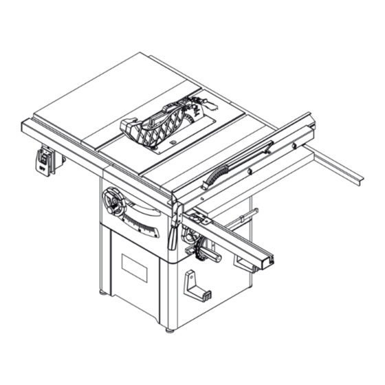
Summary of Contents for MAKSIWA SC.1100.X
- Page 1 SC.1100.X 10” Table Saw - 3 Wire 220 V - 1 Phase INSTRUCTION MANUAL ATTENTION: READ THIS MANUAL BEFORE USING THE MACHINE.
- Page 2 Congratulations, you just purchased the SC.1100.X Maksiwa Table Saw, which was developed with the Maksiwa’s highest standards of technology and quality. Your SC.1100.X Maksiwa Table Saw allows you to have the highest productivity in woodworking. It should be noted that to use this machine with maximum effi ciency, you should read and understand the instructions in this manual.
- Page 3 Furthermore, the manual must be kept to hand and within the vicinity of the machine so that it is accessible to operators when using, maintaining or repairing the machine. Maksiwa International Inc. 4100 N Powerline Rd, Suite D3 Pompa-...
-
Page 4: Table Of Contents
Contents General..................................05 Symbol legend ..............................05 1.2 Information on the operating instructions ....................05 Liability and warranty.............................05 Copyright................................06 1.5 Spare parts..............................06 1.6 Disposal .................................06 2. Safety Regulations...............................07 2.1 Workspace..............................07 Maintainance ..............................07 Machine Safety..............................08 3.Specifi cations..............................13 3.1 Technical Specifi cations ...........................13 3.2 Electrical Requirements ..........................13 4. -
Page 5: General
1 General 1 General 1.1 Symbol legend Important technical safety instructions in this manual are marked with symbols. These instructions for work safety must be followed. In all these particular cases, special attention must be paid in order to avoid accidents, injury to persons or material damage. -
Page 6: Copyright
1 General manual must be read carefully before commencing any work on or with this machine. The manufacturer shall not be liable for damage and/or faults resulting from the disregard of instructions in the manual. The text and images do not necessarily represent the delivery contents. The images and graphics are not depicted on a 1:1 scale. -
Page 7: Safety Regulations
2 Safety Regulations 2 Safety Regulations For your own safety, read all of the instructions and precautions before operating tool. • Wear proper apparel. Do not wear loose clothing, gloves, neckties, rings, bracelets or other jewelry which may get caught in moving parts of machine. •... -
Page 8: Machine Safety
2 Safety Regulations • Maintain proper adjustment of rip fence and blade guard. • Never adjust saw while running. Disconnect power to avoid accidental start-up. • Have damaged or worn power cords replaced immediately. • Keep blade sharp for effi cient and safest operation. 2.3 Machine Safety •... - Page 9 2 Safety Regulations and possible injury from them can usually be avoided by: • Maintaining rip fence parallel to saw blade. • Keeping saw blade sharp. Replace or sharpen anti-kick-back pawls when points become dull. • Keeping saw blade guard, spreader, and anti-kickback pawls in place and operating properly. The spreader must be in alignment with the saw blade and the pawls must stop a kickback once it has started.
- Page 10 2 Safety Regulations boards can help to prevent kickbacks and binding. Feather boards should be used for all “non thru-sawing” operations. • Never reach in back of the cutting tool with either hand to hold down or support the workpiece, remove wood scraps, or for any other reason.
- Page 11 2 Safety Regulations...
- Page 12 2 Safety Regulations KNOW YOUR CUTTING TOOLS • Dull, gummy, improperly sharpened or set cutting tools can cause material to stick, jam, stall saw, or kickback at operator. Minimize potential injury by proper care and machine maintenance. WARNING: Never attempt to free a stalled saw blade without first turning saw OFF. •...
-
Page 13: Specifi Cations
3 Specifi cations 3 Specifi cations 3.1 Technical Specifi cations Please choose proper power source, voltage and frequency that are shown in the label for your machine. 10” Contractor Table Saw Motor 2.5 Hp 8 Amp or A 1800W Table Size 20″X 27″... - Page 14 3 Specifi cations WARNING: Improper connection of equipment grounding conductor can result in the risk of electrical shock. Equipment should be grounded while in use to protect operator from electrical shock. WARNING: This machine is for indoor use only. Do not expose to rain or use in damp locations. GUIDELINES FOR EXTENSION CORDS USE PROPER EXTENSION CORD.
-
Page 15: Installation
4 Installation 4 Installation 4.1 Unpacking and Checking Contents Carefully unpack the table saw and all its parts, and compare against the illustration following. WARNING: • To avoid injury from unexpected starting, do not plug the power cord into a power source receptacle during unpacking and assembly. -
Page 16: Assembly
4 Unpacking and Checking Contents Hardware Bag #1 (For extension table assembly) M10X25 Socket head bolt (6) 10mm Lock washer 10mm Flat washer Hardware Bag #2 (For guide rail) M8X25 Hex head bolt (6) M8X25 Socket head bolt (6) 8mm Flat washer (18) M8 Hex nut (12) Hardware Bag #3 M8X16 Carriage bolt (16) (For assembling stand to main machine) - Page 17 4 Unpacking and Checking Contents INSTALL HANDWHEELS Refer to following fi gure • Remove saw cabinet from the carton box and place upside down on cardboard on fl oor. • Place one of the handwheels onto the blade raise/lower shaft located on the front of the cabinet. Align the groove in the back of the handwheel with the pin.
- Page 18 4 Unpacking and Checking Contents ASSEMBLE THE STAND BASE Refer to following fi gure Assemble the two side stands, front brace with label and rear brace together using 8 carriage bolts, fl at washers and nuts. ATTACH STAND BASE TO CABINET Refer to following fi...
- Page 19 4 Unpacking and Checking Contents ATTACH EXTENSION TABLES Refer to following fi gure • With help of another person, place the table saw upright. Adjust the feet to make the table saw stand stably. • With help of another person, Assemble extension table to the table using socket head bolts, lock washers and fl...
- Page 20 4 Unpacking and Checking Contents INSTALL BLADE Refer to following fi gure • Unlock the knob and remove the table insert. • Raise blade assembly all the way up. • Pull arbor lock and use wrench to loosen fl ange nut. Remove fl ange and nut from arbor. •...
- Page 21 4 Unpacking and Checking Contents • Gauge this tooth with the dowel rod. If the tooth is in the same position, relative to the miter gauge slot, the table is parallel with the blade. In short, the miter gauge slots must be parallel with the blade. This means that when measuring distance between blade and miter gauge slot at the front and rear of the blade, the distances will be equal.
- Page 22 4 Unpacking and Checking Contents ATTACH SWITCH ASSEMBLY Refer to following fi gure. • Remove the cover from left front rail, Insert bolt heads into T-slot on bottom of left front rail. Replace the cover. • Slide switch assembly 6″to 8″from left end of rail. •...
- Page 23 4 Unpacking and Checking Contents RIVING KNIFE TO BLADE ADJUSTMENT The riving knife should be in line with the saw blade. If adjustment is necessary: • Loosen the two socket pan head screws slightly. • Adjust the set screws as needed to correct the out-of-align blade attachment. Do small adjustments and check.
- Page 24 4 Unpacking and Checking Contents ATTACH SWITCH ASSEMBLY Refer to following fi gure. • Remove the thread forming screw and the battery cover. Insert the two AAA batteries and replace the battery cover and thread forming screw. The laser is an optional accessory. If your machine has not this part, skip this step. •...
- Page 25 4 Unpacking and Checking Contents CHECK AND ADJUST THE LASER The laser is an optional accessory. If your machine has not this part, skip this step. • Turn on the switch, check if the laser line is in the middle of the blade and blade mark. If not, some adjustments are needed.(The blade mark should have been aligned with blade) •...
- Page 26 4 Unpacking and Checking Contents INSTALL RIP FENCE Refer to following fi gure. • Place rip fence assembly onto rails. • Rip fence should ride freely on rails. Once rip fence is completely installed, it should be parallel with the miter gauge and perpendicular to the table.
- Page 27 4 Unpacking and Checking Contents STORE BLADE GUARD, MITER GAUGE, RIP FENCE AND OTHER PARTS Refer to following fi gure.
-
Page 28: Operating Procedures
5 Operating Procedures 5 Operating Procedures 5.1 Description The 10″ contractor saw offers precise cutting performance for all woods up to 3-1⁄8″ thick. The saw is designed for the professional user and is ruggedly constructed for continuous service. The 10″Saw is recommended for use with a 10″... -
Page 29: Adjustments
5 Operating Procedures 5.3 Adjustment BLADE HEIGHT ADJUSTMENT Refer to following fi gure. • Blade height is controlled by handwheel on the front of the saw. • To adjust height, loosen locking hand knob. Rotate knob counterclockwise approximately three turns. Turn handwheel to desired blade height. - Page 30 5 Operating Procedures MITER GAUGE ADJUSTMENT Refer to following fi gure. • Miter gauge supplied with saw is equipped with individually adjustable index stops at 0° and 45°, right and left, and can be manually adjusted up to 60° right and left. Adjustment to index stops can be made by loosening locking nut and tightening or loosening three adjusting screws.
- Page 31 5 Operating Procedures NOTE: This is for micro-adjustment only. If fence cannot be adjusted square, recheck rail adjustment. • Lock fence in position and recheck. Continue this procedure until fence is square to the table. PARALLEL ADJUSTMENT • Position fence so that fence edge is aligned with slot edge. •...
-
Page 32: Types Of Cuts/Operations
5 Operating Procedures RIP FENCE OPERATION • Unlock the fence by lifting the locking lever. Using the scale for placement, position the rip fence. Lock the rip fence into position by placing the locking lever in the down position. • The rip fence is used for the following operations: ripping, bevel ripping, ploughing, resawing, rabbeting and dadoing. - Page 33 5 Operating Procedures to the blade guard assembly and personal injury. Before starting the motor, test the operation by feeding the workpiece into the blade guard assembly. If the blade guard assembly contacts the blade, place the workpiece under the blade guard assembly, not touching the blade, before starting the motor. WARNING: Certain workpiece shapes, such as molding may not lift the blade guard assembly properly.
- Page 34 5 Operating Procedures RESAWING This cut is performed with the rip fence, and is used to rip a workpiece through its thickness rather than across its fl at width. Do not attempt to resaw bowed or warped material. NOTE: It may be necessary to remove blade guard and use work supports as well as push blocks when performing this operation.
- Page 35 5 Operating Procedures IMPORTANT: Do not allow facings to interfere with operation of blade guard. DUST COLLECTING • Saw is fi tted with a 4″male exhaust port. • Before starting saw, see that all adjustments are properly made and guards in place. With power disconnected, turn pulley by hand to make sure everything is correct before connecting power and starting saw.
-
Page 36: Maintenance
6 Maintenance 6 Maintenance 6.1 Safety instructions Warning! Risk of injury: improper maintenance can cause serious injury or damage. For this reason, this work may only be carried out by authorised, trained personnel who are familiar with how to operate the machine and in strict observance of all safety instructions. -
Page 37: Changing The Blade Saw
6 Maintenance replaced immediately. • Make sure teeth of anti-kickback pawls are always sharp. • Sharpen dull teeth using a few light strokes of a smooth cut fl at fi le. 6.5 Changing the Saw Blade Refer to following fi gure. WARNING: Turn the power switch “OFF”... -
Page 38: Troubleshooting
7 Troubleshooting 7 Troubleshooting SYMPTOM POSSIBLE CAUSE(S) CORRECTIVE ACTION Saw stops or will not start 1.Overload tripped 1.Allow motor to cool and reset by pushing reset switch 2.Saw unplugged from wall or motor 2.Check all plug connections 3.Fuse blown or circuit breaker tripped 3.Replace fuse or reset circuit breaker 4.Cord damaged 4.Replace cord... - Page 39 7 Troubleshooting SYMPTOM POSSIBLE CAUSE(S) CORRECTIVE ACTION Frequent opening of fuses or 1.Motor overloaded 1.Feed work slower into blade circuit breakers 2.Fuses or circuit breakers do not 2.Install proper size fuses or circuit breakers have suffi cient capacity Material kicked back from 1.Rip fence out of alignment 1.Align rip fence with miter slot blade...
-
Page 40: Exploded View
8 Exploded View 8 Exploded View... - Page 41 8 Exploded View Part A PARTS NUMBER ITEM PARTS NAME SPMAK-SCX-A01 FENCE SPMAK-SCX-A02 END CAP FOR FRAME SPMAK-SCX-A03 FENCE SEAT FRAME SPMAK-SCX-A04 5-0.8X10 PAN HEAD SCREW SPMAK-SCX-A05 SPRING PIECE FOR HOLDING PUSH STICK SPMAK-SCX-A06 FENCE SLIDING LOCK PLATE SPMAK-SCX-A07 FLAT WASHER SPMAK-SCX-A08 KNOB SPMAK-SCX-A09...
- Page 42 8 Exploded View Part A PARTS NUMBER ITEM PARTS NAME PARTS NUMBER ITEM PARTS NAME SPMAK-SCX-A42 4X30MM SPRING PIN SPMAK-SCX-A81 BATTERY BOX ASSEMBLY SPMAK-SCX-A82 BATTERY COVER SPMAK-SCX-A43 PIVOT PIN SPMAK-SCX-A83 THREAD FORMING SCREW SPMAK-SCX-A44 4X12MM SPRING PIN SPMAK-SCX-A84 AAA BATTERY SPMAK-SCX-A45 LATCH SPMAK-SCX-A46...
- Page 43 8 Exploded View...
- Page 44 8 Exploded View Part B PARTS NUMBER ITEM PARTS NAME PARTS NUMBER ITEM PARTS NAME SPMAK-SCX-B01 LEFT REAR RAIL SPMAK-SCX-B38 SWITH MOUNTING PLATE SPMAK-SCX-B02 RIGHT REAR RAIL SPMAK-SCX-B39 5-0.8X10MM FLAT HEAD SCREW SPMAK-SCX-B03 8-1.25X25MM SOCKET HEAD BOLT SPMAK-SCX-B40 SWITCH SPMAK-SCX-B04 8MM FLAT WASHER SPMAK-SCX-B41 4-0.7X16MM PAN HEAD SCREW...
- Page 45 8 Exploded View...
- Page 46 8 Exploded View Part C PARTS NUMBER ITEM PARTS NAME SPMAK-SCX-C01 TRUNNION SPMAK-SCX-C02 8MM FLAT WASHER SPMAK-SCX-C03 8MM LOCK WASHER SPMAK-SCX-C04 8-1.25X25MM SOCKET HEAD BOLT SPMAK-SCX-C05 BEVEL BASE SPMAK-SCX-C06 SPRING SPMAK-SCX-C07 8-1.25X12MM SOCKET HEAD BOLT SPMAK-SCX-C08 RETAINING RING SPMAK-SCX-C09 SPRING SPMAK-SCX-C10 LOCKING PLATE SPMAK-SCX-C11...
- Page 47 8 Exploded View Part C PARTS NUMBER ITEM PARTS NAME PARTS NUMBER ITEM PARTS NAME SPMAK-SCX-C42 6MM FLAT WASHER SPMAK-SCX-C81 3X20MM SPRING PIN SPMAK-SCX-C82 BEARING FIXING PLATE SPMAK-SCX-C43 6-1.0X12MM SOCKET HEAD BOLT SPMAK-SCX-C83 BEARING SPMAK-SCX-C44 GUIDE ROD SPMAK-SCX-C84 RETAINING RING SPMAK-SCX-C45 8-1.25X30MM SOCKET HEAD BOLT SPMAK-SCX-C85...
- Page 48 8 Exploded View...
- Page 49 8 Exploded View Part D PARTS NUMBER ITEM PARTS NAME SPMAK-SCX-D01 4-0.7X8MM PAN HEAD SCREW SPMAK-SCX-D02 4MM FLAT WASHER SPMAK-SCX-D03 REAR BLADE GUARD BRACKET SPMAK-SCX-D04 FRONT BLADE GUARD BRACKET SPMAK-SCX-D05 LEFT PANEL SPMAK-SCX-D06 CONNECTING PANEL SPMAK-SCX-D07 CONNECTING PANEL SPMAK-SCX-D08 8-1.25X16MM CARRIAGE BOLT SPMAK-SCX-D09 FLAT WASHER SPMAK-SCX-D10...
-
Page 50: Wiring Diagram
9 Wiring Diagram 9 Wiring Diagram WIRING DIAGRAM 3-Wire 220V 1Phase... -
Page 51: Terms Of Warranty
10 Terms of Warranty 10 Terms of Warranty MAKSIWA assures the owner that their equipment, identifi ed by the Serial number issued on the Warranty Terms. The equipment under warranty, for two (2) years, is as followed: 1. The warranty period begins on the date of the Warranty Terms below. - Page 52 Imported by: Maksiwa International Inc. 4100 N Powerline Rd, Suite D3 Pompano Beach, Florida ZIP Code: 33073 Telephone: +1 (754) 205-6717 | Call us free: +1 (844) 319-6594 E-mail: tech@maksiwa.com www.maksiwa.com...
Need help?
Do you have a question about the SC.1100.X and is the answer not in the manual?
Questions and answers