
Related Manuals for MAKSIWA BMD.3200.IR


Summary of Contents for MAKSIWA BMD.3200.IR
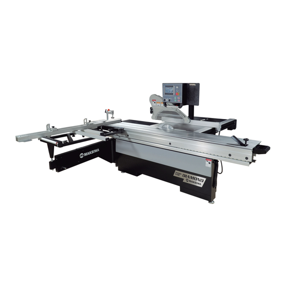
- Page 1 BMD.3200.IR Diamond Panel Saw - 10 HP - 1 Phase INSTRUCTION MANUAL ATTENTION: READ THIS MANUAL BEFORE USING THE MACHINE.
- Page 2 Congratulations, you just purchased the BMD.3200.IR Maksiwa Panel Saw, which was developed with the Maksiwa’s highest standards of technology and quality. Your BMD.3200.IR Maksiwa Panel Saw allows you to have the highest productivity in woodworking. It should be noted that to use this machine with maximum effi ciency, you should read and understand the instructions in this manual.
- Page 3 Furthermore, the manual must be kept to hand and within the vicinity of the machine so that it is accessible to operators when using, maintaining or repairing the machine. Maksiwa International Inc. 909 S Rogers Circle suite 11...
-
Page 4: Table Of Contents
BMD.3200.IR Table of Content General Information ........................2 Safety Precautions .......................... 2 Machine Information ........................6 Specification ......................6 Machine structure ....................7 Installation ............................8 Assembling Sliding Table ..................8 Assembling Crosscut Frame & Crosscut fence ............9 Assembling Extension Table .................. 11 Assembling Motorized Rip Fence ................ -
Page 5: General Information
BMD.3200.IR General Information For any problems regarding this machine, please contact the local agent or service department. Kindly provide the following information: Machine model number Serial number Purchase date Approximate number of working hours Effect only adjustments and maintenance operations on machine as indicated in this manual. - Page 6 BMD.3200.IR Don't use machines in damp or wet locations, or expose them to rain. Please provide a suitable illumination around the machine for safety operation. Keep children and visitors away All children and visitors should be kept in a safe distance from working area.
- Page 7 Our authorized agency is responsible for a future connection of the machine with ancillary equipment only if we ourselves have designed such connection. Reduce the risk of unintentional starting. Make sure switches of control panel are OFF position before operating. Never leave machine running unattended.
- Page 8 Use of a push block and a push stick: A push stick should be used to avoid working with hands close to the saw blade. Push blocks should be between 300mm and 400mm long, 80mm to 100mm wide and 15mm to 20mm high. Push blocks should be used when cutting small work pieces and in circumstances where it is necessary to push the work piece against the fence.
-
Page 9: Machine Information
3 Machine Information 3.1 Specification Model 3200mm 3800mm Sliding table dimension 3200x395mm 3800x395mm Cast Iron table 548x896mm Extension table (rear) 952x896mm Extension table (front) 830X320mm Table size 1500x1726mm Main saw blade (Max.) 355mm Main saw bore φ30mm Max. cutting height at 90 (355mm) 105mm Max. -
Page 10: Machine Structure
Machine structure A. Sliding Table Crosscut Fence B. Hold Down Digital Readout for length (Optional) Miter fence Crosscut Frame D. Edge shoe Swing Arm Motorized rip fence Support tube Control panel Digital readout for angle (Optional) G. Overhead guard Support leg for 3800mm sliding table H. -
Page 11: Installation
4 Installation 4.1 Assembling Sliding Table Sliding Table is detached from the machine and needed to be assembled before using. Please following the steps to assembled it successfully. ※Please put the sliding table on the machine frame before started to assemble it※ 1. -
Page 12: Assembling Crosscut Frame & Crosscut Fence
Sticker 5. Sliding table locker. Please follow the sticker to lock or unlock the sliding table. 4.2 Assembling Crosscut Frame & Crosscut fence The Crosscut Frame and Crosscut Fence are detached from the machine and need to be assembled before use. - Page 13 3. Turn the Crosscut Fence to match the arrows on the crosscut frame. 4. Tighten the screws for the parts in their position: A. Insert the screws into the hole on the arrow A B. Insert the screws into the hole on the arrow B C.
-
Page 14: Assembling Extension Table
4.2.3 Assembling Flip Stop Slide the flip stop unit into groove M. Then tight Knob N to fix. Assembling Extension Table ※The extension table must be the same level as the cast iron table. If the extension table is lower, the gap must be less than 0.2mm for smooth operation※... -
Page 15: Assembling Motorized Rip Fence
4.3.3 Assembling Extension Table (Left Side) 1. Keep the extension table close with cast iron table. Please check with the fence plate to make sure they are in the same level. 2. Tighten two screws A. 3. Adjust the extension table and the sliding table are in the same level with screws B. Extension Table 4.4 Assembling Motorized Rip Fence ※The motorized rip fence frame should as same level as the cast iron table. -
Page 16: Assembling Saw Blade Guard
Adjust the set screws B close to the rip fence. Insert the aluminum ruler in to the rip fence with Low and High side. High Side Low Side Insert the connector. Connect the break (For A405E/NC only) Plug in the break connector Lock the two screws Control panel Frame D... - Page 17 Frame A Loosen the nut and washer on the machine frame then put on frame A. Make sure the screw A1 is close to the frame. Do not tighten A1, washer and nuts now. Close to the frame Frame A Washers &...
- Page 18 Frame C Fit the dust frame C to the square pipe. Insert the Circle Dust pipe into the dust frame C completely and tighten the screws A. Make sure the washers touch the square pipe, and tighten the screw B. Dust Frame C Square pipe Circle dust pipe...
- Page 19 Assembling the dust hood to the dust frame. Tighten the screws to insert the dust hood into dust frame. M6x12mm Use hose clamp to tighten the hose. Frame D Tighten four screws with the panel from D for the next step. Tighten two screws with the panel frame D for the next step.
-
Page 20: Assembling Saw Blade And Riving Knife
Control Panel Tighten four screws to fix the panel with the panel frame D. Corrugated pipe Tighten the seven screws to fix each clamps with the frame, then install the corrugated pipe in the clamps. This clamps is packed with control panel. - Page 21 Insert the round bar C into the hole on the working table for locking the spindle, and use a wrench to remove the nut D & flange E. Fit the saw blade then tight nut D & flange E to fix the saw blade. Please check the direction of the blade.
-
Page 22: Assembling Edge Shoe And Hold Down
Assembling Edge Shoe and Hold Down 1.2.1 Assembling Edge shoe 1. Loosen knob A and slide the edge shoe into sliding table. 2. Lock A at the ideal location. 1.2.2 Assembling Hold down Loose stopper A and slide the hold down into the sliding table groove. Lock stopper A at your ideal location. -
Page 23: Machine Operation
2 Machine Operation Wiring and Test Run WARNING: WORK ON ELECTRICAL FITTINGS MAY ONLY BE CARRIED OUT BY QUALIFIED PERSON. SERIOUS INJURY MAY OCCURRED WHEN LACK OF ATTENTION. Check the voltage and the power frequency are corresponding to the machine nameplate. -
Page 24: Touch Screen Panel
Touch Screen Panel A. Switch for main blade angle B. Micro-adjustment for blade angle D. MAIN BLADE ON Button—Turn on the main saw C. Switch for main blade going up/down blade. E. SCORING BLADE ON Button—Start the scoring F. MAIN BLADE OFF Button—Stop the main blade blade. - Page 25 5.3.2 Calibration When you receive the machine, need to do motorized rip fence calibration before operating the machine to make sure the dimension shows on the control panel screen is equal to the actual dimension. Please follow the following steps to do calibration. 1.
- Page 26 5.3.6 Grooves /concealed cuts Kindly notice that before operating the grooves function, make sure to input the blade information or choose the blade that you are currently using. Lock & Unlock Press lock button A to prevent accidental pressing during the operation. (lock sign will show as B). 1.
-
Page 27: Crosscut Fence Operation And Adjustment
2. Enter password to enter setting page. 3. Setting for long side and short side rip fence. 5.3.10 Travel Alarm The Max travel is set at 1350mm, Min travel is at 0mm. When exceed the system setting, the screen will display a warning signal. 5.3.11 Change to Manual Control After receiving the new machine, not using the machine for a long time, or having the power shut off suddenly, the memory of the... - Page 28 Make sure the nut E touched against the pad. 5.4.2 Crosscut Fence for different angel Loosen the knob A and B and the knob C. Move the crosscut fence to the desired value. Tighten the Knob B and C. 5.4.3 Flip Stop Operation and Adjustment When cutting the panel, please make sure the panel is close to the flip stop for the accurate cutting.
- Page 29 Please make sure the flip stops and the crosscut fence is on the same level. The seam Red line Crosscut Fence Adjustment-1/2 When the setting value is not the same as the cutting value, please make the following steps to improve the accuracy of the operation.
-
Page 30: Motor Speed And Belt Change
Motor Speed and Belt Change 5.5.1 Speed Change 1. Turn the nut A clockwise, and then the motor will be moved up and belt will be slacked. 2. Put the belt to the desired speed. 3. Turn the nut A on opposite side counterclockwise, the motor will be moved to the original position. 3000 rpm 4000 rpm 5000 rpm... - Page 31 5.6.1 Saw Blade Verticality Adjustment (follow the steps) 1. Loosen the nuts A and screw out the screw B. 2. Loosen the nuts C and screw out the screw D. 3. Loosen the nut E and adjust the screw F. 4.
- Page 32 BMD.3200.IR...
- Page 33 QCA405M010124 ITEM PART NO. PART NAME SIZE Q`TY NOTE 0010 208247A Upper Front Guard 0020 SH100700 Hex. Head Screw M10*1.5*35 0030 NH101700 M10x1.5 0040 208439 Machine Body 0050 SH121000 Hex. Head Screw M12*1.75*50 0060 WS120000 Spring Washer 0070 203410 Ring 0080 WS060000 Spring Washer...
- Page 34 BMD.3200.IR ITEM PART NO. PART NAME SIZE Q`TY NOTE 0640 NH162400 M16*2*13T 0650 SS080500 Set Screw M8*1.25*25 0660 NH081300 M8*13 0700 NH061000 M6*φ16 0710 WF061620 Flat Washer 0810 SH101040 Hex. Head Screw M10*1.5*50 0820 NH101400 M10x1.5P 0840 NH121900 M12*1.75*10t M12*φ40 t3mm...
- Page 35 BMD.3200.IR ITEM PART NO PART NAME SIZE Q`TY NOTE SS100400 Set Screw M10*20 NH101700 Hex Nut 207077 Left Ext. Plate 207151 Left Ext. Plate R / S SR100500 Cap Screw M10*25 206643 Table 207078 Ext. Plate M10*ψ20 WF102030 Washer WS100000...
- Page 36 BMD.3200.IR ITEM PART NO PART NAME SIZE Q`TY NOTE 208069 Cover AB136012-5 Door Safety Switch Assembly 136012 Door Safety Switch 709411 Strain Relief PG11 SP040700 Pan Head Plate M4*35 206341 Fix Plate IC200810 STOP CORD 0.75x2Cx3.1Mx4Y.E SH059300 Hex Head Bolt...
- Page 37 BMD.3200.IR ITEM PART NO PART NAME SIZE Q`TY NOTE WS050000 Lock Washer M5*ψ10 WF051010 Washer 150527 Sponge SF089300 Hex Head Bolt(+)/W M8x12 ψ5" 206118 Dust Port ψ4" 208423 Dust Port 207940 Hinge WF051010 Washer M5*10 WS050000 Lock Washer SR059200 Cap Screw...
- Page 38 BMD.3200.IR...
- Page 39 BMD.3200.IR ITEM PART NO PART NAME SIZE Q`TY NOTE SR100402 Cap Screw M10*1.5P*20(LH) M10*ψ40*3t WF104030 Washer 205788 Pulley 50HZ X2 / CE 205794 Pulley 60HZ X2 / CSA 994220 Thrust Bearing 32X54X1.5MM 210018A Main Motor Plate 210008 Main Motor Shaft...
- Page 40 BMD.3200.IR...
- Page 41 BMD.3200.IR ITEM PART NO PART NAME SIZE Q`TY NOTE 999455 AB208186 Fix Block ASM NH121900 Hex Nut M12*1.75 M12*ψ40 WF124030 Washer SS050200 Setscrew M5x10 206461 Fix Block 208186 Fix Block SC120800 Carriage Screw M12x40 SI069400 Counter Sunk Screw M6*16 208141 M24*3.0P...
- Page 42 BMD.3200.IR ITEM PART NO PART NAME SIZE Q`TY NOTE SR080400 Cap Screw M8×20 WS080000 Lock Washer 210038 Gear wheel...
- Page 43 BMD.3200.IR ITEM PART NO PART NAME SIZE Q`TY NOTE SR101600 Cap Screw M10*80 205568 Angle Driver NL101700 Lock Nut NH101700 Hex Nut SR120500 Cap Screw M12*25 WS120000 Lock Washer M12*ψ30 WF123025 Washer 208062 Shaft M6*ψ16 WF061620 Washer WS060000 Lock Washer...
- Page 44 BMD.3200.IR ITEM PART NO PART NAME SIZE Q`TY NOTE 207139 NH142200 Hex Nut 208124 Plate SI080500 Counter Sunk Screw M8*25 RS100000 Retaining Ring AB205545 Height Driver 205545 Height Driver 205545-1 Gear 994657 Switch SR101300 Cap Screw M10*65 NH101700 Hex Nut...
- Page 45 BMD.3200.IR ITEM PART NO PART NAME SIZE Q`TY NOTE SH120440 Hex Head Bolt M12×20 206320 Flange 206321 Shaft BB600304 Ball Bearing 6003LLB RS150000 Int. Retaining Ring ψ26*ψ34 t=0.3 ( 6202 ) WW263403 Wave Washer RR350000 Int. Retaining Ring 206497 Shaft...
- Page 46 BMD.3200.IR ITEM PART NO PART NAME SIZE Q`TY NOTE SH089400 Hex Head Bolt M8*16 WS080000 Lock Washer M8*ψ30 WF083030 Washer 206590 Spring 208172 Shaft SS069300 Setscrew M6*12 205919 Ring...
- Page 47 BMD.3200.IR ITEM PART NO PART NAME SIZE Q`TY NOTE SR080400 Cap Screw M8*20 WS080000 Lock Washer M8*ψ30 WF083030 Washer 207033 Ring 207034 Ring SH069400 Hex Head Bolt M6*16 208120 Fix Plate M6*ψ13 WF061310 Washer WS060000 Lock Washer NH061000 Hex Nut...
- Page 48 BMD.3200.IR ITEM PART NO PART NAME SIZE Q`TY NOTE 206627 Pully 50Hz 206336 Pully 60Hz LF150020 Belt 18WX380L 50Hz/60Hz 208184 Shaft SJ080400 Button Head Screw M8*20 WS080000 Lock Washer 208185 Plate M14*ψ35 WF143530 Washer NH142200 Hex Nut MH206301 Scoring Motor 0.75P (M20P)
- Page 49 BMD.3200.IR ITEM PART NO PART NAME SIZE Q`TY NOTE 205208 Sliding Tube 203545 Hex Nut 205505 Screw Threads 203470 Plug 40*120 NH081300 Hex Nut SH080400 Hex Head Screw M8*20 207948 Rotary Arm BB620203A Ball Bearing 6202LLU 208405 Shaft...
- Page 50 BMD.3200.IR ITEM PART NO PART NAME SIZE Q`TY NOTE AB203356 Ring Assembly BB620202 Ball Bearing 6202ZZ 203356 Ring 203357 Shaft RS150000 Retaining Ring AB203348 Roller Assembly 203349 Shaft 203348 Roller BB620202 Ball Bearing 6202ZZ RS150000 Retaining Ring M8*ψ18 WF081818 Washer...
- Page 51 BMD.3200.IR ITEM PART NO PART NAME SIZE Q`TY NOTE 203116 Fixed Plate ψ8×20 PS082000 Spring Pin SI100400 Counter Sunk Screw M10×20 200910 Plug 40×80 203979 Frame 201576 Hole Plugs HP-09 NH081300 Hex Nut WS080000 Lock Washer 201103 T-Nut M8x1.25p...
- Page 52 BMD.3200.IR ITEM PART NO PART NAME SIZE Q`TY NOTE 203284 Hole Plugs HP-19 SH120801 Screw M12×1.25×40 AB208181 Square Brace ST040200 Tap Screw #8x3/8" 208196 Cover 208181 Square Brace 203302 Roller RR320000 Retaining Ring 203094 Plug BB620103A Ball Bearing 6201LLU 017058...
- Page 53 BMD.3200.IR ITEM PART NO PART NAME SIZE Q`TY NOTE 201576 Hole Plugs HP-09 207734 Fixed Plate WS080000 Lock Washer SR080200 Cap Screw M8×10...
- Page 54 BMD.3200.IR...
- Page 55 BMD.3200.IR ITEM PART NO PART NAME SIZE Q`TY NOTE AB207207 Flip Stop Assembly 207203 Shaft 207207 Flip Stop 207208 Washer 207263 Knob M8x1.25px42L 200472 Washer M8x20x1 WF081818 Washer M8x18 207235 207200 207201 Stop Bracket 207223 Pipe 207202 Magnifier 203286 Set Screw...
- Page 56 BMD.3200.IR ITEM PART NO PART NAME SIZE Q`TY NOTE SJ080400 Button Head Screw M8*20 203598 Screw M8*1.25p M8*ψ18 WF081818 Washer SR060800 Cap Screw M6*40 207219 Fixed Block 207220 Plate SS069100 Setscrew M6*6 207218 Fixed Block SS080700 Setscrew M8*35 SS089300 Setscrew...
- Page 57 BMD.3200.IR...
- Page 58 BMD.3200.IR ITEM PART NO. PART NAME SIZE Q`TY NOTE 0010 SP050910 Pan Head Screw M5*0.8*45 0020 WS040000 Spring Washer M4*φ8 0030 WF040808 Flat Washer 0040 NH061000 0050 WS060000 Spring Washer 0060 WS050000 Spring Washer 0070 SR049300 Hex. Socket Screw M4*0.7*12 M6xφ19...
- Page 59 BMD.3200.IR ITEM PART NO PART NAME SIZE Q`TY NOTE 2395160D Table 395x1600mm 2395250D Table 395x2500mm 2395320D Table 395x3200mm 203423 Hander SH050200 Hex Head Bolt M5*10 203520 Fixed Block SR080500 Cap Screw M8*25 205246 Fixed Block SR080500 Cap Screw M8*25...
- Page 60 BMD.3200.IR...
- Page 61 BMD.3200.IR ITEM PART NO PART NAME SIZE Q`TY NOTE SR060400 Cap Screw M6*20 WS060000 Lock Washer M6*ψ19 WF061920 Washer AB207981 Link ASM SH100700 Hex Head Bolt M10*35 WS100000 Lock Washer SR060900 Cap Screw M6*45 WS060000 Lock Washer SH100700 Hex Head Bolt M10*35 M10*ψ20...
- Page 62 BMD.3200.IR ITEM PART NO PART NAME SIZE Q`TY NOTE LM207032 Warning Label LM207033 Warning Label AB205355 Protection Hood ASM 207867 Guard SP040200 Pan Head Screw M4*10 205355 Protection Hood AB207868 Roller ASM SP040200 Pan Head Screw M4*10 205356 Protection Hood...
- Page 63 BMD.3200.IR...
- Page 64 BMD.3200.IR ITEM PART NO. PART NAME SIZE Q`TY NOTE 0010 207770 Support Tube 0020 SR080500 Hex. Socket Screw M8*1.25*25 0030 WS080000 Spring Washer M8*φ18*t1.8 0040 WF081818 Flat Washer 0050 207774 Support Frame 0060 NH203000 M20*2.5*t16mm 0070 203338 Washer 0080 205116...
- Page 65 BMD.3200.IR ITEM PART NO PART NAME SIZE Q`TY NOTE 203017 Gear Wheel ψ10*30 PP103000 210055 Encoder Fixed Plate 206454 Encoder Shaft Ring 203154 Encoder M6*ψ19 WF061920 Washer WS060000 Lock Washer SJ069400 Button Head Screw M6*16 M3*ψ6 WF030605 Washer WS030000 Lock Washer...
- Page 66 BMD.3200.IR ITEM PART NO PART NAME SIZE Q`TY NOTE AB207065-2 Down Press ASM D,E,M 207143 Adjust Handle 100271 Ball Knob M8×P1.25 207070 Handle Bar 207067 RS140000 Ext. Retaining Ring 207069 Spring 207145 207065 Down Press 207068 Shaft NH602300 Hex Nut...
- Page 67 BMD.3200.IR ITEM PART NO PART NAME SIZE Q`TY NOTE AB208390 Block SI100400 Counter Sunk Screw M10*20 208390-1 Block 208390-2 Handle 208390-3 Hole Plugs ST040600 M4*30 208390-4 Knob M10*16...
- Page 68 BMD.3200.IR ITEM PART NO PART NAME SIZE Q`TY NOTE 201830 EDGE SHOE PLATE φ5*18 PS051800 SPINT PIN M10*φ20*2 WF102025 FLAT WASHER 203718 KNOB 201829 T-NUT M10x1.5p...
- Page 69 BMD.3200.IR ITEM PART NO PART NAME SIZE Q`TY NOTE 200526 Fence Plate AC198170AB1 Miter Gauge Assembly S, A AC204295A Miter Gauge Assembly 1600MM S, A 198170A Miter Gauge Body NH050800 Hex Nut SR050500 Cap Screw M5×25 SP049300 Pan Head Bolt M4×12...
- Page 70 BMD.3200.IR AB136012-5 ITEM PART NO PARTS NAME SIZE Q`TY NOTE 0010 AB136012A 0050 IC200810 Stop Control Cord 0.75x2Cx3.1Mx4Y AB136012A ITEM PART NO PARTS NAME SIZE Q`TY NOTE 0010 136012A Door Safety Switch AZD-1112(UL) 0020 709411 Strain Relief PG11 0030 SP040500 Pan Head Screw (+)
- Page 71 BMD.3200.IR...
- Page 72 BMD.3200.IR ITEM PART NO. PART NAME SIZE Q`TY NOTE 0010 203131 Fixed Base 0070 203199 Thrust Washers LFW1615 0080 SR040200 Hex. Socket Screw M4*0.7*10 0090 WS040000 Spring Washer M4*φ8 0100 WF040808 Flat Washer 0670 203178 Bushing 0680 203180 Steel Ball...
- Page 73 BMD.3200.IR ITEM PART NO. PART NAME SIZE Q`TY NOTE 0020 203296 Fixed Base 0040 203297 Metal Push Button Switch 0050 203481 Nylon Box Adapter 0060 203475 Hose NGN-12B 1090 IC205106 Proximity Switch Signal Wire 22AWGx4Cx2.5M 1100 IC205041 Fine Core Control Cord...
- Page 74 BMD.3200.IR ITEM PART NO. PART NAME SIZE Q`TY NOTE 0090 WS040000 Spring Washer 0390 203782 Base 0400 SR049200 Hex. Socket Screw M4*0.7*8 0410 203889 Hose Adapter SS-P400 PGB-06B 0420 203888 Hose "MM-WN-21-3/4" 0490 203997 Fixed Plate 0500 203184 Proximity Switch...
- Page 75 BMD.3200.IR AB207752 ITEM PART NO. PART NAME SIZE Q`TY NOTE 0010 207752 Fixed Plate 0020 205397A Micro Switch D4MC-5020 0030 SP040510 Pan Head Screw (+) M4*0.7*25 AB207751 ITEM PART NO. PART NAME SIZE Q`TY NOTE 0010 207751 Fixed Plate 0020...
- Page 76 BMD.3200.IR...
- Page 77 BMD.3200.IR ITEM PART NO. PART NAME SIZE Q`TY NOTE 0090 WS040000 Spring Washer 0110 SS049100 Set Screw M4*0.7*6 0120 205323 DC Motor DC24V 0130 NH061000 0140 203156 Timing Pulley 0150 SS049000 Set Screw M4*0.7*4 0160 WS060000 Spring Washer 0170 SR060400 Hex.
- Page 78 BMD.3200.IR ITEM PART NO. PART NAME SIZE Q`TY NOTE 0580 NH121900 M12*1.75*10t 0590 205937 Fixed Base 0600 BB620104B Ball Bearing 0620 SS121200 Set Screw M12*1.75*60 M6*φ16 0630 WF061620 Flat Washer 0640 203795 Liner Slide Rail 0650 203990 Fixed Base 0660...
- Page 79 BMD.3200.IR ITEM PART NO. PART NAME SIZE Q`TY NOTE 0010 208440B Electric Control Box M6*φ16 0020 WF061620 Flat Washer 0030 WS060000 Spring Washer 0040 NH061000 0050 207318 Strain Relief MGB40-25B 0060 203860 Strain Relief PGB21-18B 0070 AB208441B Electric Control Box Asm.
- Page 80 BMD.3200.IR ITEM PART NO. PART NAME SIZE Q`TY NOTE 0010 WS050000 Spring Washer R2SNL-22φ 0020 205240 Two-stage Selector Switch 0030 994855A R2 PRCF Flat Head Buckle Dust Cover 0040 994993 Inch Switch R2 PNF-1A-W 0050 994855 R2 PNF-1A-G Flat Head Push Button Switch...
- Page 81 BMD.3200.IR AB28541B ITEM PART NO. PART NAME SIZE Q`TY NOTE 0010 AB208440B Electric Control Box Asm. 0020 QYAB208540B Electric Control Plate 0030 AB203296 Clutch Metal Switch Box Set 0040 AB203869-4 Coupling Asm. AB208441B ITEM PART NO. PART NAME SIZE Q`TY...
- Page 82 10 Terms of Warranty 10 Terms of Warranty MAKSIWA assures the owner that their equipment, identifi ed by the Serial number issued on the Warranty Terms. The equipment under warranty, for two (2) years, is as followed: 1. The warranty period begins on the date of the Warranty Terms below.
- Page 83 Imported by: Maksiwa International Inc. 990 S Rogers Circle, Suite 11 Boca Raton, Florida ZIP Code: 33487 Telephone: +1 (754) 205-6717 | Call us free: +1 (844) 319-6594 E-mail: tech@maksiwa.com www.maksiwa.com...
Need help?
Do you have a question about the BMD.3200.IR and is the answer not in the manual?
Questions and answers