Table of Contents
Advertisement
Quick Links
TLD7002-16SYS_EVAL board
User guide
LITIX
Pixel Rear
™
Multi-channel LED driver
Z8F80459854
About this document
Scope and purpose
The scope of this user manual is to provide instructions on the use of the TLD7002-16SYS_EVAL board.
The TLD7002-16SYS_EVAL is an evaluation platform for the TLD7002-16ES LED driver, which features:
•
16 independent channels set from 5 mA to 76.5 mA
•
Power stages can be paralleled for higher currents
•
16 independent 14 bits PWM engines
•
UART over CAN interface (HSLI High speed lighting interface)
•
OTP (one time programmable) configuration memory
Intended audience
Hardware and Firmware engineers
Evaluation board
This board is to be used during the design-in process for evaluating and measuring characteristic curves, and
for checking datasheet specifications.
Note:
PCB and auxiliary circuits are NOT optimized for final customer design.
User guide
Please read the sections "Important notice" and "Warnings" at the end of this document
www.infineon.com
Revision 1.00
2023-05-29
Advertisement
Table of Contents

Related Manuals for Infineon TLD7002-16SYS EVAL


Summary of Contents for Infineon TLD7002-16SYS EVAL
-
Page 1: About This Document
This board is to be used during the design-in process for evaluating and measuring characteristic curves, and for checking datasheet specifications. Note: PCB and auxiliary circuits are NOT optimized for final customer design. User guide Please read the sections "Important notice" and "Warnings" at the end of this document Revision 1.00 www.infineon.com 2023-05-29... -
Page 2: Important Notice
Boards provided by Infineon Technologies. The design of the Evaluation Boards and Reference Boards has been tested by Infineon Technologies only as described in this document. The design is not qualified in terms of safety requirements, manufacturing and operation over the entire operating temperature range or lifetime. -
Page 3: Safety Precautions
TLD7002-16SYS_EVAL board User guide Safety precautions Safety precautions Note: Please note the following warnings regarding the hazards associated with development systems. Table 1 Safety precautions Caution: The device surface of the evaluation or reference board may become hot during testing. Hence, necessary precautions are required while handling the board. -
Page 4: Table Of Contents
TLD7002-16SYS_EVAL board User guide Table of contents Table of contents About this document ..............1 Important notice . -
Page 5: The Board At A Glance
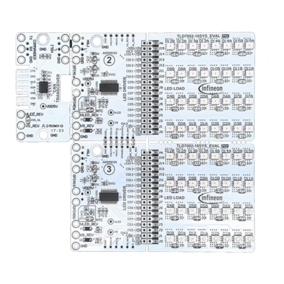
TLD7002-16SYS_EVAL board User guide 1 The board at a glance The board at a glance TLD7002-16SYS_EVAL consists of one PCB, with 3 snappable sections: • 1 x CAN transceiver section • 2 x LED driver, TLD7002-16ES section • 2 x LED load section The 5 sections of the PCB can be snapped in order to mimic different system implementation. -
Page 6: Block Diagram
TLD7002-16SYS_EVAL board User guide 1 The board at a glance Block diagram Below, find the block diagram of the TLD7002-16SYS_EVAL. Note: Microcontroller and power supply are not included TRANSCEIVER SECTION LED DRIVER SECTION LED LOAD SECTION HSLI-H VLED HSLI-L Microcontroller VLED GPIN0 OUT0... -
Page 7: Quick Start
TLD7002-16SYS_EVAL board User guide 2 Quick start Quick start Operational modes summary The TLD7002-16SYS_EVAL can operate in three different manners. • Fail safe operation • GPINx direct drive control • HSLI bus control Fail safe operation The TLD7002-16ES devices on the TLD7002-16SYS_EVAL are programmed watchdog timeout set to 2 s. If within 2 seconds from the board power up, no HSLI communication is received by the TLD7002-16ES, then the fail safe configuration will turn on as shown in figure below. -
Page 8: Gpinx Direct Drive Control
TLD7002-16SYS_EVAL board User guide 2 Quick start GPINx direct drive control Close JVS_VL to use a single power supply (or use 2 power supplies for VS and VLED_REV) Connect the GND at the - terminal of a 6 V to 20 V 500 m A power supply Connect VS_REV to the + terminal of the power supply Connect GPIN0 or GPIN1 test points to VDD5V test point directly to VBAT or to the VDD test point The respective GPIN0 or GPIN1 OTP configuration, pre-written in the OTP, will light up... -
Page 9: Hsli Bus Control
TLD7002-16SYS_EVAL board User guide 2 Quick start HSLI bus control The TLD 7002-16ES can be connected to an external microcontroller UART. The TLD7002-16ES device drivers are available on the TLD7002-16ES webpage [2]. Close JVS_VL to use a single power supply Connect the GND at the - terminal of a 6 V to 20 V 1 A power supply Connect VS_REV to the + terminal of the power supply Connect GND, RX, TX COMMANDER test points to a commander µC GND, RX(UART), TX(UART) -
Page 10: Control With Arduino Uno And Demo Software Sketch
TLD7002-16_ES website [4]. The OTP wizard can be used to read the OTP configuration files. The OTP wizard tool (see Figure 7) can used to read and interpret the .ocfg configuration files. The tool can be installed from the Infineon developer center [5]. User guide Revision 1.00 2023-05-29... - Page 11 TLD7002-16SYS_EVAL board User guide 2 Quick start The TLD7002-16SYS_EVAL sketch program can be used to emulate the OTP, because the OTP emulation function is implemented in the code - OTPemuComplete function present in file TLD7002FuncLayer.c. See TLD7002-16 OTP programming application note for further details on OTP emulation and programming.
-
Page 12: System Design
TLD7002-16SYS_EVAL board User guide 3 System design System design Schematics Figure 8 Schematic User guide Revision 1.00 2023-05-29... -
Page 13: Layout
TLD7002-16SYS_EVAL board User guide 3 System design Layout Figure 9 Top layer User guide Revision 1.00 2023-05-29... -
Page 14: Bill Of Material
TLD7002-16SYS_EVAL board User guide 3 System design Figure 10 Bottom layer Bill of material Table 3 Bill of material Designator Value Quantity Footprint Voltage Note C1, C10 470nF C0603 X7R 5% C12, C13 47pF C0603 X7R 5% C2, C11 4.7nF C0603 X7R 5% CNTC, CO0, CO1, CO2, CO3,... - Page 15 TLD7002-16SYS_EVAL board User guide 3 System design Table 3 (continued) Bill of material Designator Value Quantity Footprint Voltage Note CVDD1, CVL2, CVL3, CVS1 100nF c0603 X7R 5% CVDD2 4.7uF c0805 X7R 5% CVL1, CVS2 470nF C0805 X7R 5% D0A, D0B, D1A, D1B, D2A, Red LED LED SMD Lite On –...
-
Page 16: References
TLD7002-16SYS_EVAL board User guide References References Arduino IDE downloads:; https://www.arduino.cc/en/software Infineon TLD7002-16ES https://www.infineon.com/cms/en/product/power/lighting-ics/litix-automotive- led-driver-ic/litix-pixel-rear/tld7002-16es/ Infineon TLD7002-16ES OTP programming procedure https://www.infineon.com/ dgdl/Infineon-Infineon-TLD7002-16ES_OTP_programming_procedure-AN-v01_20-EN-ApplicationNotes- v01_20-EN.pdf?fileId=8ac78c8c80f4d32901816672cf833ad1 Infineon TLD7002-16SYS_EVAL https://www.infineon.com/cms/en/product/power/lighting-ics/litix- automotive-led-driver-ic/litix-pixel-rear/tld7002-16es/?tab=~%27boards_designs#!designsupport Infineon Developer Center Launcher https://www.infineon.com/cms/en/design-support/tools/utilities/ infineon-developer-center-idc-launcher/ User guide Revision 1.00 2023-05-29... -
Page 17: Revision History
TLD7002-16SYS_EVAL board User guide Revision history Revision history Document Date of Description of changes version release 2023-05-29 Rev.1.00 • Initial release User guide Revision 1.00 2023-05-29... -
Page 18: Disclaimer
Infineon Technologies, Email: erratum@infineon.com Infineon Technologies’ products may not be used in any applications where a failure of the product or any consequences of the use thereof can reasonably be Document reference expected to result in personal injury.
Need help?
Do you have a question about the TLD7002-16SYS EVAL and is the answer not in the manual?
Questions and answers