Table of Contents
Advertisement
Quick Links
TLD5542-1IVREG-EVAL evaluation board
User Manual
About this document
Product description
TLD5542-1: H-Bridge buck-boost DC-DC controller designed for high power, high efficiency automotive
applications
• Constant current (LED) and constant voltage regulation
• SPI for diagnostics and control
• Limp home function (Fail-safe mode)
• EMC optimized device: Spread spectrum
Scope and purpose
Scope of this user manual is to provide to the audience instructions on usage of the TLD5542-1 device evaluation
board TLD5542-1IVREG-EVAL schematic version S01 PCB version P01
The TLD5542-1IVREG-EVAL is an evaluation platform for the TLD5542-1, which can work as buck-boost LED driver,
or as a voltage regulator.
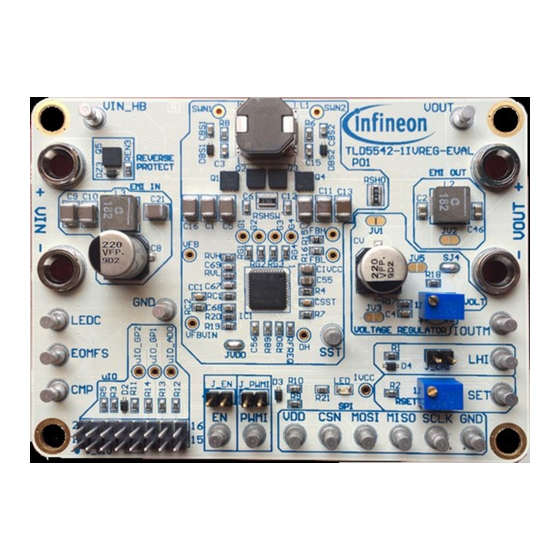
Figure 1
TLD5542-1IVREG-EVAL device evaluation board
Intended audience
Hardware engineers, software engineers, system architects
User Manual
Please read the Important Notice and Warnings at the end of this document
Rev.1.00
www.infineon.com
page 1 of 18
2020-05-25
Advertisement
Table of Contents

Related Manuals for Infineon TLD5542-1IVREG-EVAL


Summary of Contents for Infineon TLD5542-1IVREG-EVAL
-
Page 1: About This Document
Scope of this user manual is to provide to the audience instructions on usage of the TLD5542-1 device evaluation board TLD5542-1IVREG-EVAL schematic version S01 PCB version P01 The TLD5542-1IVREG-EVAL is an evaluation platform for the TLD5542-1, which can work as buck-boost LED driver, or as a voltage regulator. -
Page 2: Table Of Contents
Set up as voltage regulator - Limp home mode (μC-less – no PC GUI) ..........5 Connecting the board to the μIO stick....................6 Infineon μIO stick and Infineon Toolbox ..................8 Install and launch Config Wizard ......................9 Board control with PC GUI ......................10 Basic user interface .......................... -
Page 3: Description
TLD5542-1 provides complete control and diagnostics through the SPI interface. The device can be used in microcontroller-less applications, because of the limp home mode. The TLD5542-1IVREG-EVAL is an evaluation platform for the TLD5542-1 as LED driver or voltage regulator. The default configuration is constant current LED driver with 1.5 A maximum output current. -
Page 4: Quick Start Procedure
Quick start procedure Quick start procedure Below, step by step procedures are laid out for setup and running the TLD5542-1IVREG-EVAL in all available configurations. Installation procedure for PC GUI (graphical user interface) and μIO stick interface is described from Chapter 4. -
Page 5: Set Up As Voltage Regulator - Limp Home Mode (Μc-Less - No Pc Gui)
TLD5542-1IVREG-EVAL evaluation board User Manual Quick start procedure Set up as voltage regulator - Limp home mode (μC-less – no PC GUI) Configure solder jumper for VREG (Figure 6), if I > 3 A bypass RSHO with a solder joint on the resistor top... -
Page 6: Connecting The Board To The Μio Stick
Voltage regulator with μIO stick: connect μIO and power supply Launch Infineon toolbox, see chapter 5 to learn how to control the eval board with the PC GUI In case of voltage regulator: rotate RVOLT trimmer to obtain the maximum desired V... - Page 7 TLD5542-1IVREG-EVAL evaluation board User Manual Quick start procedure Figure 11 Voltage regulator with μIO stick: Adjust full scale (100% ADIM) V Connect the load NOTE: It is possible to adjust output voltage from 0 to full scale (previously set by RVOLT) with the GUI Analog dimming knob, but the best transient response is when analog dimming is set to 100%.
-
Page 8: Infineon Μio Stick And Infineon Toolbox
Infineon μIO stick and Infineon Toolbox 4 Infineon μIO stick and Infineon Toolbox The Infineon μIO stick is an interface device for controlling Infineon boards/kits during run time through PC. Enables the connection between the evaluation board and USB for SPI programming and monitoring ... -
Page 9: Install And Launch Config Wizard
Search for “Config Wizard for LED” and click on “Install” button Figure 14 Install Config Wizard for LED Select “My Tools” tab on Infineon Toolbox Press “Start” on the config wizard for LED to start Figure 15 Start Config Wizard tool... -
Page 10: Board Control With Pc Gui
TLD5542-1IVREG-EVAL evaluation board User Manual Board control with PC GUI 5 Board control with PC GUI The TLD5542-1 PC GUI consists of 2 interfaces: Basic user interface Engineering user interface The GUI works only if the TLD5542-1 EVALBOARD is correctly connected to the μIO stick and power supply is applied to the V connector. -
Page 11: Engineering User Interface
TLD5542-1IVREG-EVAL evaluation board User Manual Board control with PC GUI On the “Compensation Setting” tab (see Figure 18 ), it is possible to tune the compensation transfer function in order to have the smoothest transition from buck-boost to boost mode, which depends by the switching... - Page 12 TLD5542-1IVREG-EVAL evaluation board User Manual Board control with PC GUI It is possible to describe each command with a comment and to save the list of commands by clicking on the “Save” button. It is possible to set the delay applied before executing the next command in the “Delay” column, the accuracy of the timer is approximately 10 ms.
-
Page 13: Operating Range And Power Derating
User Manual Operating range and power derating Operating range and power derating The TLD5542-1IVREG-EVAL has very high efficiency, so it can deliver up to 60 W at the output without a heat sink at T = 25°C, V = 12 V ( see Figure 22 for power-derating curve). -
Page 14: Electrical Characteristics
TLD5542-1IVREG-EVAL evaluation board User Manual Electrical characteristics Electrical characteristics Table 1 TLD5542-1IVREG-EVAL version S01 P01 – electrical characteristics Value Parameter Symbol Unit Note/Test Condition Min. Typ. Max. Input voltage Power derating may occur for < 9 V LED driver mode Out voltage –... -
Page 15: Pcb Layout
TLD5542-1IVREG-EVAL evaluation board User Manual PCB layout 8 PCB layout Figure 23 PCB layout top view User Manual 15 of 18 Rev.1.00 2020-05-25... -
Page 16: Schematic
TLD5542-1IVREG-EVAL evaluation board User Manual Schematic 9 Schematic Figure 24 Schematic User Manual 16 of 18 Rev.1.00 2020-05-25... -
Page 17: Revision History
TLD5542-1IVREG-EVAL evaluation board User Manual Revision history Revision history Date of release Description of changes Document version Rev. 1.00 2020-05-25 Initial User Manual User Manual 17 of 18 Rev.1.00 2020-05-25... - Page 18 With respect to any examples, hints or any typical 81726 München, Germany values stated herein and/or any information WARNINGS regarding the application of the product, Infineon Technologies hereby disclaims any and all Due to technical requirements products may contain warranties and liabilities of any kind, including dangerous substances.
Need help?
Do you have a question about the TLD5542-1IVREG-EVAL and is the answer not in the manual?
Questions and answers