Table of Contents
Advertisement
Quick Links
Z8F80605411
TLD6099-2S-S_EVAL
User guide
About this document
Scope and purpose
This user guide provides instructions on the usage of the TLD6099-2ES dual-channel SEPIC topology evaluation
board (TLD6099-2S-S_EVAL).
Intended audience
This user guide is intended for engineers performing measurements and checks with the TLD6099-2ES in dual
SEPIC topology.
Evaluation board
This board is to be used during the design-in process for evaluating and measuring characteristic curves, and
for checking datasheet specifications.
Note:
PCB and auxiliary circuits are NOT optimized for final customer design.
Boards do not necessarily meet safety, EMI, quality standards (for example UL, CE) requirements.
User guide
Please read the sections "Important notice" and "Warnings" at the end of this document
www.infineon.com
Rev.1.10
2024-05-07
Advertisement
Table of Contents

Subscribe to Our Youtube Channel
Related Manuals for Infineon TLD6099-2S-S EVAL Series


Summary of Contents for Infineon TLD6099-2S-S EVAL Series
-
Page 1: About This Document
PCB and auxiliary circuits are NOT optimized for final customer design. Boards do not necessarily meet safety, EMI, quality standards (for example UL, CE) requirements. User guide Please read the sections "Important notice" and "Warnings" at the end of this document Rev.1.10 www.infineon.com 2024-05-07... -
Page 2: Important Notice
Boards provided by Infineon Technologies. The design of the Evaluation Boards and Reference Boards has been tested by Infineon Technologies only as described in this document. The design is not qualified in terms of safety requirements, manufacturing and operation over the entire operating temperature range or lifetime. -
Page 3: Safety Precautions
TLD6099-2S-S_EVAL User guide Safety precautions Safety precautions Note: Please note the following warnings regarding the hazards associated with development systems. Table 1 Safety precautions Warning: The evaluation or reference board contains DC bus capacitors, which take time to discharge after removal of the main supply. Before working on the drive system, wait 5 minutes for capacitors to discharge to safe voltage levels. -
Page 4: Table Of Contents
TLD6099-2S-S_EVAL User guide Table of contents Table of contents About this document ..............1 Important notice . -
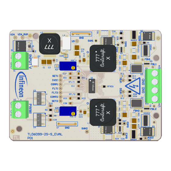
Page 5: The Board At A Glance
TLD6099-2S-S_EVAL User guide 1 The board at a glance The board at a glance The TLD6099-2S-S_EVAL is an evaluation board that embeds TLD6099-2ES, a multi-topology LED driver with Adaptive Output Discharge (AOD) feature. The board is designed to operate in SEPIC topology for both channels, that enables the user to regulate stable output current to a LED chain with a total forward voltage that can be lower, higher, or equal to the input voltage. -
Page 6: Block Diagram
TLD6099-2S-S_EVAL User guide 1 The board at a glance Block diagram Figure 2 Simplified schematic Main features • Diagnostic is always enabled to protect the load • Output current overshoots are strongly limited from AOD functionality Board parameters and technical data Table 2 Parameters Parameter... -
Page 7: System And Functional Description
TLD6099-2S-S_EVAL User guide 2 System and functional description System and functional description Getting started The basic board configuration includes two LED drivers, both utilizing the SEPIC topology, enabling stable output current regulation for an LED chain with a total forward voltage that can be lower, higher, or equal to the input voltage. -
Page 8: Output Current Variation
TLD6099-2S-S_EVAL User guide 2 System and functional description Output current variation It is possible to vary the output current (analog dimming) from 0 to 1 A by adjusting trimmers RSET1 and RSET2. These trimmers must be enabled with jumpers X27 and X28. Connect maximum 13 white LEDs in series per channel. -
Page 9: Digital Dimming
TLD6099-2S-S_EVAL User guide 2 System and functional description Digital dimming To drive channels with an external pulse-width modulation (PWM) dimming source, remove jumpers X3 and X4, and provide signals on connector PWMI (X2). Jumper ID Condition Description Open PWMI1 connected to PWMI CH1 input connector Open PWMI2 connected to PWMI CH1 input connector Open... -
Page 10: System Design
TLD6099-2S-S_EVAL User guide 3 System design System design Schematics TSM-103-01-S-SV TSM-103-01-S-SV SM6T39CA-E3/5B BZT52C10SQ-7-F 1, 2, 3 5, 6, 7, 8 1, 2, 3 5, 6, 7, 8 1, 2, 3 5, 6, 7, 8 1, 2, 3 5, 6, 7, 8 User guide Rev.1.10 2024-05-07... -
Page 11: Layout
TLD6099-2S-S_EVAL User guide 3 System design Figure 6 Schematics Layout Figure 7 Top layer User guide Rev.1.10 2024-05-07... - Page 12 TLD6099-2S-S_EVAL User guide 3 System design Figure 8 Internal layer 1 User guide Rev.1.10 2024-05-07...
- Page 13 TLD6099-2S-S_EVAL User guide 3 System design Figure 9 Internal layer 2 User guide Rev.1.10 2024-05-07...
- Page 14 TLD6099-2S-S_EVAL User guide 3 System design Figure 10 Bottom layer User guide Rev.1.10 2024-05-07...
-
Page 15: Bill Of Material
3.3 µH Coilcraft MSS1260T-332NLB 98 Ω Wurth Elektronik 7427932 MP1, MP2 BGA STD 050 ABL Components BGA STD 050 IPD90P03P4L-04 Infineon Technologies IPD90P03P4L-04 Q2, Q3, Q4, Q6 IAUC26N10S5L245 Infineon Technologies IAUC26N10S5L245 10 kΩ Stackpole Electronics RMCF0603FT10K0 R2, R3 150 mΩ... - Page 16 3 System design Table 3 (continued) Bill of material Designator Value Manufacturer Manufacturer P/N RSET1, RSET2 10 kΩ Vishay T93YA103KT20 Infineon Technologies TLD6099-2ES X1, X2, X9, X10 1935776 Phoenix Contact 1935776 X3, X4 TSM-103-01-S-SV Samtec TSM-103-01-S-SV X5, X6 M7583-05...
-
Page 17: System Performance
TLD6099-2S-S_EVAL User guide 4 System performance System performance Figure 11 Comparison between efficiency and input voltage range This efficiency performance is obtained with: Output current Output load 13 power white LEDs in series Ambient temperature 25°C User guide Rev.1.10 2024-05-07... -
Page 18: Glossary
TLD6099-2S-S_EVAL User guide Glossary Glossary pulse-width modulation (PWM) A technique to encode an analog value into the duty cycle of a pulsing signal with arbitrary amplitude. User guide Rev.1.10 2024-05-07... -
Page 19: Revision History
TLD6099-2S-S_EVAL User guide Revision history Revision history Document Date of Description of changes version release Rev.1.10 2024-05-07 • About this document is updated Rev.1.00 2024-04-30 • Initial release User guide Rev.1.10 2024-05-07... -
Page 20: Disclaimer
Infineon Technologies, All Rights Reserved. information given herein in the real application. Infineon Technologies’ products may not be used in Infineon Technologies hereby disclaims any and all any applications where a failure of the product or...
Need help?
Do you have a question about the TLD6099-2S-S EVAL Series and is the answer not in the manual?
Questions and answers