Infineon TLD5099EP User Manual
Voltage-mode boost to ground evaluation kit
Hide thumbs
Also See for TLD5099EP:
- User manual (14 pages) ,
- Quick start manual (15 pages) ,
- User manual (19 pages)
Table of Contents
Advertisement
Quick Links
User Manual
Voltage-mode boost to ground evaluation kit
TLD5099EP
About this document
Product description
The TLD5099EP is an AEC qualified DC/DC boost controller.
•
Built in diagnosis and protection features
•
ENABLE control pin available
•
Spread spectrum modulator to improve the EMI performance
Scope and purpose
Scope of this user manual is to provide to the audience instructions on usage of TLD5099EP voltage-mode boost
to ground evaluation board.
Intended audience
This document is intended for engineers who need to perform measurements and check performances with
TLD5099EP voltage-mode boost to ground evaluation board.
Table of contents
About this document . . . . . . . . . . . . . . . . . . . . . . . . . . . . . . . . . . . . . . . . . . . . . . . . . . . . . . . . . . . . . . . . . . . 1
Table of contents . . . . . . . . . . . . . . . . . . . . . . . . . . . . . . . . . . . . . . . . . . . . . . . . . . . . . . . . . . . . . . . . . . . . . . . 1
1
Description . . . . . . . . . . . . . . . . . . . . . . . . . . . . . . . . . . . . . . . . . . . . . . . . . . . . . . . . . . . . . . . . . . . . . . . . . . . . .2
2
Quick start procedure . . . . . . . . . . . . . . . . . . . . . . . . . . . . . . . . . . . . . . . . . . . . . . . . . . . . . . . . . . . . . . . . . . .4
3
Auto-enable configuration . . . . . . . . . . . . . . . . . . . . . . . . . . . . . . . . . . . . . . . . . . . . . . . . . . . . . . . . . . . . . . 5
4
Schematics . . . . . . . . . . . . . . . . . . . . . . . . . . . . . . . . . . . . . . . . . . . . . . . . . . . . . . . . . . . . . . . . . . . . . . . . . . . . .6
5
PCB layout . . . . . . . . . . . . . . . . . . . . . . . . . . . . . . . . . . . . . . . . . . . . . . . . . . . . . . . . . . . . . . . . . . . . . . . . . . . . . 8
6
Bill of material . . . . . . . . . . . . . . . . . . . . . . . . . . . . . . . . . . . . . . . . . . . . . . . . . . . . . . . . . . . . . . . . . . . . . . . . . 9
7
Efficiency measurements . . . . . . . . . . . . . . . . . . . . . . . . . . . . . . . . . . . . . . . . . . . . . . . . . . . . . . . . . . . . . . 11
8
Maximizing efficiency . . . . . . . . . . . . . . . . . . . . . . . . . . . . . . . . . . . . . . . . . . . . . . . . . . . . . . . . . . . . . . . . . .12
9
Minimizing EMI emissions . . . . . . . . . . . . . . . . . . . . . . . . . . . . . . . . . . . . . . . . . . . . . . . . . . . . . . . . . . . . . . 13
10
Revision history . . . . . . . . . . . . . . . . . . . . . . . . . . . . . . . . . . . . . . . . . . . . . . . . . . . . . . . . . . . . . . . . . . . . . . . 14
Disclaimer . . . . . . . . . . . . . . . . . . . . . . . . . . . . . . . . . . . . . . . . . . . . . . . . . . . . . . . . . . . . . . . . . . . . . . . . . . . . 15
User Manual
www.infineon.com
Please read the Important Notice and Warnings at the end of this document
2020-01-29
Advertisement
Table of Contents

Related Manuals for Infineon TLD5099EP


Summary of Contents for Infineon TLD5099EP
-
Page 1: Table Of Contents
• Spread spectrum modulator to improve the EMI performance Scope and purpose Scope of this user manual is to provide to the audience instructions on usage of TLD5099EP voltage-mode boost to ground evaluation board. Intended audience This document is intended for engineers who need to perform measurements and check performances with TLD5099EP voltage-mode boost to ground evaluation board. -
Page 2: Description
1 Description Description Evaluation board for medium power application with TLD5099EP configured in voltage-mode boost to ground topology. It can be implemented as a DC-DC power supply with constant voltage output. Default configuration of the board is voltage-mode boost to ground topology without any additional features enabled. - Page 3 Voltage-mode boost to ground evaluation kit TLD5099EP 1 Description Figure 2 Simplified schematic Table 1 Performance summary Parameter Conditions Value Input supply voltage Parameter degradation below 6.5 V 8 V to 27 V Down to 6.5 V for less than 2 s...
-
Page 4: Quick Start Procedure
Voltage-mode boost to ground evaluation kit TLD5099EP 2 Quick start procedure Quick start procedure The default configuration of the board has all additional features disabled. Jumper is positioned in 1-2 position. In this configuration ENABLE signal has to be applied on X18 (max 45 V). If another output voltage is required, the voltage divider composed of R24, R25, R26 must be changed according to the rule that a 300 mV dropout should be present across R25 when the desired voltage is present in the output. -
Page 5: Auto-Enable Configuration
Voltage-mode boost to ground evaluation kit TLD5099EP 3 Auto-enable configuration Auto-enable configuration By positioning the jumper on the position 2-3, an external enable signal to start the device is no longer needed. Figure 4 Auto-enable configuration User Manual 2020-01-29... -
Page 6: Schematics
Voltage-mode boost to ground evaluation kit TLD5099EP 4 Schematics Schematics Figure 5 Input filter User Manual 2020-01-29... - Page 7 Voltage-mode boost to ground evaluation kit TLD5099EP 4 Schematics Figure 6 Main power User Manual 2020-01-29...
-
Page 8: Pcb Layout
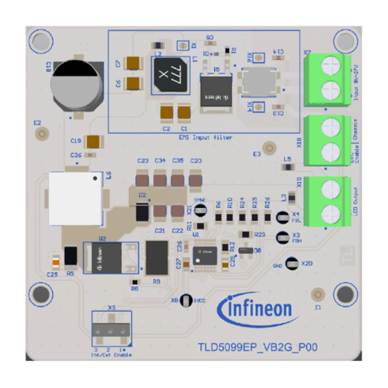
Voltage-mode boost to ground evaluation kit TLD5099EP 5 PCB layout PCB layout Figure 7 PCB layout top view Figure 8 PCB layout bottom view User Manual 2020-01-29... -
Page 9: Bill Of Material
12kΩ Vishay CRCW080512K0FK 150Ω Vishay CRCW0805150RFK TLD5099EP Infineon Technologies TLD5099EP X1, X14, X16 Solder Jumper 2 Infineon Technologies AG Solder Jumper 2 Pins Pins X2, X15, X18 1935776 Phoenix Contact 1935776 X3, X4, X8, X20, X21 5001 Keystone 5001 User Manual... - Page 10 Voltage-mode boost to ground evaluation kit TLD5099EP 6 Bill of material Table 2 Bill of material (continued) Designator Value Manufacturer Manufacturer order number TSM-103-01-S-SV Samtec TSM-103-01-S-SV User Manual 2020-01-29...
-
Page 11: Efficiency Measurements
Voltage-mode boost to ground evaluation kit TLD5099EP 7 Efficiency measurements Efficiency measurements Figure 9 Efficiency vs. input voltage This efficiency performance has been obtained with: Table 3 Parameters influencing efficiency Output load: 139 Ω power resistor EMI filter: Totally bypassed by closing the jumpers X1, X14 and X16... -
Page 12: Maximizing Efficiency
Voltage-mode boost to ground evaluation kit TLD5099EP 8 Maximizing efficiency Maximizing efficiency This evaluation board has been designed to reach a fair compromise between efficiency performance and EMI emissions compliance. Nevertheless, if the maximum efficiency is needed, the following actions are suggested:... -
Page 13: Minimizing Emi Emissions
Voltage-mode boost to ground evaluation kit TLD5099EP 9 Minimizing EMI emissions Minimizing EMI emissions This evaluation board has been designed to reach a fair compromise between efficiency performance and EMI emissions compliance. Furthermore, this evaluation board can fulfill the class V of the CISPR25 in conducted emissions from 150 kHz to 108 MHz. -
Page 14: Revision History
Voltage-mode boost to ground evaluation kit TLD5099EP 10 Revision history Revision history Document Date of release Description of changes version Rev. 1.00 2020-01-29 First release related to evalboard S00_P00. User Manual 2020-01-29... -
Page 15: Disclaimer
Infineon Technologies, All Rights Reserved. given herein in the real application. Infineon Infineon Technologies’ products may not be used in Technologies hereby disclaims any and all warranties any applications where a failure of the product or and liabilities of any kind (including without limitation...
Need help?
Do you have a question about the TLD5099EP and is the answer not in the manual?
Questions and answers