Table of Contents
Advertisement
Quick Links
Z8F80142094
UG xxx (user guide number)
TLD5191IVREG-EVAL board
User guide
LITIX™ Power TLD5191ES
About this document
Board description
TLD5191: Four switches buck boost DC-DC controller designed for automotive applications
•
Constant current (LED) and constant voltage regulation
•
High power, high efficiency buck-boost architecture
•
Embedded PWM engine for digital dimming
•
EMC optimized device: Spread spectrum
•
Scope and purpose
The scope of this user guide is to provide instructions on the use of the TLD5191ES device evaluation board
TLD5191IVREG-EVAL schematic version S03 PCB version P02.
The TLD5191IVREG-EVAL is an evaluation platform for the TLD5191ES, which can work as buck-boost LED driver,
or as a voltage regulator.
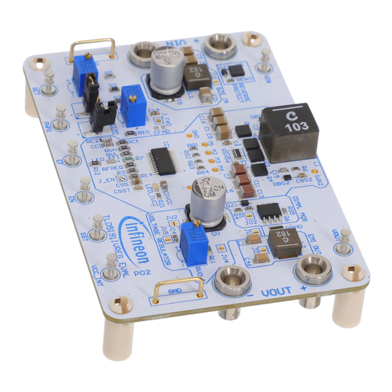
Figure 1
TLD5191IVREG-EVAL board
Intended audience
Hardware engineers
User guide
www.infineon.com
Please read the Important Notice and Warnings at the end of this document
page 1 of 17
Rev.2.00
2022-11-03
Advertisement
Table of Contents

Related Manuals for Infineon TLD5191IVREG-EVAL


Summary of Contents for Infineon TLD5191IVREG-EVAL
-
Page 1: About This Document
The scope of this user guide is to provide instructions on the use of the TLD5191ES device evaluation board TLD5191IVREG-EVAL schematic version S03 PCB version P02. The TLD5191IVREG-EVAL is an evaluation platform for the TLD5191ES, which can work as buck-boost LED driver, or as a voltage regulator. -
Page 2: Table Of Contents
TLD5191IVREG-EVAL board User guide Table of contents Table of contents About this document ......................... 1 Table of contents ........................2 Description ..........................3 Quick start procedure ....................... 4 Setup as LED driver ..........................4 3.1.1 Embedded PWM engine ........................5 Set up as voltage regulator ........................ -
Page 3: Description
The TLD5191ES provides digital and analog dimming control and one flag for diagnostics. The TLD5191IVREG-EVAL is an evaluation platform for the TLD5191ES as LED driver or voltage regulator. The default configuration delivers a constant current LED driver with 1.5 A maximum output current. The output... -
Page 4: Quick Start Procedure
Quick start procedure Quick start procedure Step-by-step procedures are laid out for setup and running the TLD5191IVREG-EVAL in all available configurations. In all configurations solder jumper J_EN has to be closed in order to enable the device via input supply lines. -
Page 5: Embedded Pwm Engine
TLD5191IVREG-EVAL board User guide Quick start procedure If an external PWM signal is intended to be used, open J_PWMI jumper Connect the LED load Connect a 12 V power supply to the V connector → the blue LED should turn on indicating V... -
Page 6: Set Up As Voltage Regulator
TLD5191IVREG-EVAL board User guide Quick start procedure Set up as voltage regulator To configure the board as voltage regulator the following jumpers needs to be configured: Table 2 Jumper position Jumper name Condition Meaning J_PWMI Closed Enable on board PWMI setting... -
Page 7: Operating Range
TLD5191IVREG-EVAL board User guide Operating range Operating range The TLD5191IVREG-EVAL has very high efficiency, so it can deliver up to 60 W at the output without a heat sink at T = 25°C, V = 12 V. Please note that the module does not implement thermal protection, so ensure proper cooling when output power exceeds 60 W or input voltage drops below 9 V. -
Page 8: Electrical Characteristics
TLD5191IVREG-EVAL board User guide Electrical characteristics Electrical characteristics Table 3 TLD5191IVREG-EVAL version S03 P02 – electrical characteristics Value Parameter Symbol Unit Note/Test Condition Min. Typ. Max. Minimum value set by resistor divider on the Input voltage – EN/INUVLO pin 2.15 41.8... -
Page 9: Efficiency Measurements
TLD5191IVREG-EVAL board User guide Efficiency measurements Efficiency measurements The following efficiency measurements have been taken under constant current configuration (LED driver). The efficiency discontinuities are given by the controller mode changes from buck to buck-boost and from buck- boost to boost. In buck-boost mode all the four external MOSFETs are switching, increasing the total losses, while in buck or boost mode only two external MOSFETs are switching. - Page 10 TLD5191IVREG-EVAL board User guide Efficiency measurements The efficiency performances have been obtained with the following configuration: Table 4 Efficiency measurement configuration EMI filters Bypassed by closing solder jumpers JI1 and JO1 PMOS dimming Bypassed by closing solder jumper JO2 Digital dimming...
-
Page 11: Bill Of Material, Layout And Schematic
TLD5191IVREG-EVAL board User guide Bill of material, layout and schematic 7 Bill of material, layout and schematic Table 5 Designator Value Footprint Quantity C1, C5, C9, C10, C16, C21 10uF C1210 C2, C46 470nF C1206 C3, C15 470pF C0603 C4, C14... - Page 12 TLD5191IVREG-EVAL board User guide Bill of material, layout and schematic Designator Value Footprint Quantity 2.2kΩ R0603 1kΩ R0805 3.3MΩ R0805 RFREQ 27kΩ R0805 RG1, RG2, RG3, RG4 10Ω R0603 0Ω R0603 RPWMI, RSET, RVOLT Bourns 3266Y-1-203LF RSHO 100mΩ R0612 RSHSW 7mΩ...
- Page 13 TLD5191IVREG-EVAL board User guide Bill of material, layout and schematic Figure 7 PCB layout top view Figure 8 PCB layer 2 User guide 13 of 17 Rev.2.00 2022-11-03...
- Page 14 TLD5191IVREG-EVAL board User guide Bill of material, layout and schematic Figure 9 PCB layer 3 Figure 10 PCB layout bottom view User guide 14 of 17 Rev.2.00 2022-11-03...
- Page 15 TLD5191IVREG-EVAL board User guide Bill of material, layout and schematic Figure 11 Schematic view User guide 15 of 17 Rev.2.00 2022-11-03...
-
Page 16: Revision History
TLD5191IVREG-EVAL board User guide Revision history 8 Revision history Document Date of release Description of changes version Rev. 2.00 2022-11-03 Updated description text • Repaired typo in Figure 2 • Updated Figure 1, Figure 3 and Figure 4, Figure 6 •... - Page 17 Infineon Technologies hereby disclaims dangerous substances. For information on the types © 2022 Infineon Technologies AG. any and all warranties and liabilities of any kind in question please contact your nearest Infineon All Rights Reserved. (including without limitation warranties of non- Technologies office.
Need help?
Do you have a question about the TLD5191IVREG-EVAL and is the answer not in the manual?
Questions and answers