Table of Contents
Advertisement
Quick Links
Z8F80417063
TLD6098-1SEPIC_EVAL
User guide
LITIX™ Power
Multitopology single -channel DC-DC controller
About this document
Product description
The TLD6098-1EP is an AEC qualified DC-DC boost controller, especially designed to drive LEDs. It embeds:
•
Built-in diagnosis and protection features
•
Pulse width modulator to implement a dimming function with reduced color shifting
•
Coded faults to easily detect the root cause of load failures
•
Voltage loop availability to implement constant output voltage power supply
The device also incorporates a spread spectrum modulator to reduce the electromagnetic emissions outside
the allowed bands.
Scope and purpose
The scope of this user guide is to provide instructions on the use of TLD6098-1SEPIC_EVAL.
Intended audience
Hardware engineers, software engineers, system architects
Evaluation board
This board is to be used during the design-in process for evaluating and measuring characteristic curves, and
for checking datasheet specifications.
Note:
PCB and auxiliary circuits are NOT optimized for final customer design.
User guide
www.infineon.com
Please read the sections "Important notice" and "Warnings" at the end of this document
Revision 1.00
2023-01-28
Advertisement
Table of Contents

Related Manuals for Infineon TLD6098-1SEPIC EVAL


Summary of Contents for Infineon TLD6098-1SEPIC EVAL
-
Page 1: About This Document
This board is to be used during the design-in process for evaluating and measuring characteristic curves, and for checking datasheet specifications. Note: PCB and auxiliary circuits are NOT optimized for final customer design. User guide Please read the sections “Important notice” and “Warnings” at the end of this document Revision 1.00 www.infineon.com 2023-01-28... -
Page 2: Important Notice
Boards provided by Infineon Technologies. The design of the Evaluation Boards and Reference Boards has been tested by Infineon Technologies only as described in this document. The design is not qualified in terms of safety requirements, manufacturing and operation over the entire operating temperature range or lifetime. -
Page 3: Safety Precautions
TLD6098-1SEPIC_EVAL User guide Safety precautions Safety precautions Note: Please note the following warnings regarding the hazards associated with development systems Table 1 Safety precautions Warning: Remove or disconnect power from the drive before you disconnect or reconnect wires, or perform maintenance work. Wait five minutes after removing power to discharge the bus capacitors. -
Page 4: Table Of Contents
TLD6098-1SEPIC_EVAL User guide Table of contents Table of contents About this document ........................1 Important notice ..........................2 Safety precautions .......................... 3 Table of contents ..........................4 The board at a glance ......................5 Scope of supply ............................6 System and functional description ................... 7 Current adjustment .......................... -
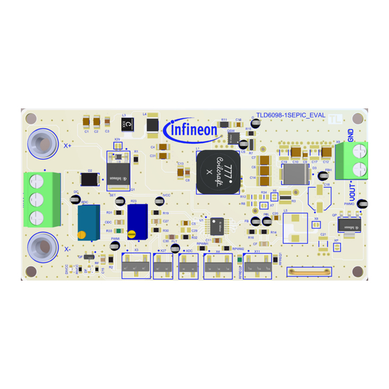
Page 5: The Board At A Glance
TLD6098-1SEPIC_EVAL User guide The board at a glance The board at a glance TLD6098-1SEPIC_EVAL is a PCB board designed to supply high power LED with TLD6098-1EP in SEPIC topology. In this configuration, the board can deliver up to 25 W. Auxiliary circuits, to protect the DC-DC and the load during the short to ground failure, are present and enabled. -
Page 6: Scope Of Supply
TLD6098-1SEPIC_EVAL User guide The board at a glance Scope of supply The jumpers are positioned as follows: Table 3 Jumper position Jumper Number Condition Meaning Open PWM adjustment disabled Close 2-3 Internal biased to provide DC = 100% External dimming disabled Open Output current analog adjustment disabled The default configuration is depicted below. -
Page 7: System And Functional Description
TLD6098-1SEPIC_EVAL User guide System and functional description System and functional description Current adjustment The output current adjustment is performed by adjusting the value of trimmer R14. The feature is enabled when the jumper X10 is closed. The output current can vary from 0% to 100% of the maximum output current. Jumpers are positioned as follows: Table 4 Jumper position... -
Page 8: Embedded Pwm Engine
TLD6098-1SEPIC_EVAL User guide System and functional description Embedded PWM engine The embedded PWM engine provides an internal PWM signal without any external dimming signal required. To enable the feature the jumper XDC is closed. RDC trimmer adjusts the dimming duty cycle by changing the voltage on the respective DC/PWMI pin. The PWM dimming frequency is set to 410 Hz. -
Page 9: External Dimming And Output Adjustment
TLD6098-1SEPIC_EVAL User guide System and functional description External dimming and output adjustment The analog output adjustment and the dimming signals can be provided by external sources. To enable the control from external sources the jumpers are positioned as follows: Table 6 Jumper position Jumper Number Condition... -
Page 10: Faults
TLD6098-1SEPIC_EVAL User guide Faults The system has been designed to use hard threshold for overvoltage detection. With this option, once the threshold is reached, the gate driver is disabled until the output voltage goes below the reset threshold. This behavior is selected with a resistor on FPWM/FAULT pin in range 18 kΩ to 90 kΩ. In this case each fault type is reported by the FPWM/FAULT pin with a dedicated PWM waveform. -
Page 11: System Design
TLD6098-1SEPIC_EVAL User guide System design System design Schematics Figure 6 Schematic Top level User guide Revision 1.00 2023-01-28... - Page 12 TLD6098-1SEPIC_EVAL User guide System design Figure 7 Schematic Input stage User guide Revision 1.00 2023-01-28...
- Page 13 TLD6098-1SEPIC_EVAL User guide System design Figure 8 Schematic Control stage User guide Revision 1.00 2023-01-28...
- Page 14 TLD6098-1SEPIC_EVAL User guide System design Figure 9 Schematic Power stage User guide Revision 1.00 2023-01-28...
-
Page 15: Layout
TLD6098-1SEPIC_EVAL User guide System design PCB Layout Figure 10 PCB layout top view Figure 11 PCB layout bottom view User guide Revision 1.00 2023-01-28... -
Page 16: Bill Of Material
1935789 8.2 µH Coilcraft MSD1278T-822MLD 2.2 µH Coilcraft XGL3520-222MED 100 Ω Wurth Elektronik 74279226101 0 Ω Not Used1 Vishay IPD90P03P4L-04 Infineon Technologies IPD90P03P4L-04 SN7002N Infineon Technologies SN7002N BSP613P Infineon Technologies BSP613P IAUZ30N06S5L140 Infineon Technologies IAUZ30N06S5L140 10 kΩ Vishay CRCW080510K0FK 10 kΩ... - Page 17 2.7 kΩ Vishay CRCW08052K70FK TLD6098-1 Infineon Technologies TLD6098-1 X3, X4, X11 TSM-103-01-S-SV Samtec TSM-103-01-S-SV Infineon Technologies AG, X6, X7, X8, X29, XP Solder Jumper 2 Pins Solder Jumper 2 Pins Infineon Technologies 1935776 Phoenix Contact 1935776 X27, XDC TSM-102-01-S-SV Samtec...
-
Page 18: References
TLD6098-1SEPIC_EVAL User guide References References Infineon: TLD6098-1EP Datasheet; https://www.infineon.com/cms/en/product/power/lighting-ics/litix- automotive-led-driver-ic/litix-power/tld6098-1ep/#!documents User guide Revision 1.00 2023-01-28... -
Page 19: Revision History
TLD6098-1SEPIC_EVAL User guide Revision history Revision history Document Date Description of changes revision Revision 1.00 2023-01-28 Initial release for evaluation board SEPIC S00_P00 User guide Revision 1.00 2023-01-28... -
Page 20: Disclaimer
For information on the types in question please contact your nearest Published by Infineon Technologies office. Except as otherwise explicitly approved by Infineon Infineon Technologies AG Technologies in a written document signed by 81726 Munich, Germany authorized...
Need help?
Do you have a question about the TLD6098-1SEPIC EVAL and is the answer not in the manual?
Questions and answers