Table of Contents
Advertisement
Quick Links
TLD5190 VOLT DEMO evaluation board
User Manual
About this document
Product description
TLD5190: H-Bridge buck-boost DC-DC controller designed for high power, high efficiency automotive
applications
• Constant current (LED driver) and constant voltage regulation
• EMC optimized device: Spread spectrum
Scope and purpose
Scope of this user manual is to provide to the audience instructions on usage of the TLD5190 VOLT DEMO
evaluation board schematic version V3.1, PCB version R2.
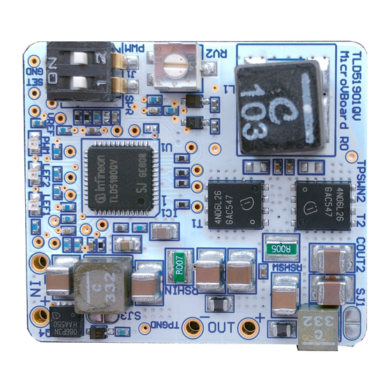
The TLD5190 VOLT DEMO is an evaluation platform for the TLD5190 set as compact voltage regulator.
Figure 1
TLD5190 VOLT DEMO evaluation board
Intended audience
Hardware engineers, system architects
User Manual
Please read the Important Notice and Warnings at the end of this document
Rev.1.00
www.infineon.com
page 1 of 12
2020-06-05
Advertisement
Table of Contents

Related Manuals for Infineon TLD5190


Summary of Contents for Infineon TLD5190
-
Page 1: About This Document
• EMC optimized device: Spread spectrum Scope and purpose Scope of this user manual is to provide to the audience instructions on usage of the TLD5190 VOLT DEMO evaluation board schematic version V3.1, PCB version R2. The TLD5190 VOLT DEMO is an evaluation platform for the TLD5190 set as compact voltage regulator. -
Page 2: Table Of Contents
TLD5190 VOLT DEMO evaluation board User Manual Table of contents Table of contents About this document ......................... 1 Table of contents ........................2 Description ..........................3 Quick start procedure ....................... 4 Operating range and power derating ..................6 Electrical characteristics ......................7 PCB - component placement ..................... -
Page 3: Description
TLD5190 can be configured as voltage regulator or LED driver. The TLD5190 VOLT DEMO is an evaluation platform for the TLD5190 as voltage regulator. The PCB is extremely compact and can fit in to small applications enclosures for fast prototyping. -
Page 4: Quick Start Procedure
Quick start procedure Quick start procedure Below, step by step procedures are laid out for setup and running the TLD5190 VOLT DEMO. Connect a dummy load at the OUT terminals which could withstand the Max a. Example: 10W 47 Ω resistor... - Page 5 TLD5190 VOLT DEMO evaluation board User Manual Quick start procedure Figure 6 Connect the real load User Manual 5 of 12 Rev.1.00 2020-06-05...
-
Page 6: Operating Range And Power Derating
User Manual Operating range and power derating Operating range and power derating The TLD5190 VOLT DEMO has very high efficiency, so it can deliver up to 40 W at the output without a heat sink at T = 25°C, V = 12 V I <... -
Page 7: Electrical Characteristics
TLD5190 VOLT DEMO evaluation board User Manual Electrical characteristics Electrical characteristics Table 1 TLD5190 VOLT DEMO schematic version V3.1 – Electrical characteristics Value Parameter Symbol Unit Note/Test Condition Min. Typ. Max. – Input voltage – – RV2 trimmer could set V as low as 1.5 V , but... -
Page 8: Pcb - Component Placement
TLD5190 VOLT DEMO evaluation board User Manual PCB - component placement 6 PCB - component placement Figure 9 PCB dimensions and component placement - top view User Manual 8 of 12 Rev.1.00 2020-06-05... -
Page 9: Schematic
TLD5190 VOLT DEMO evaluation board User Manual Schematic 7 Schematic Figure 10 Schematic User Manual 9 of 12 Rev.1.00 2020-06-05... -
Page 10: Bom
TLD5190 VOLT DEMO evaluation board User Manual About this document 8 BoM Table 2 BoM TLD5190 microVBoard BoM: TLD5190 - microVBoard R2 Configuration: Voltage mode Designator Comment Footprint 15nF 16V X7R C0402 C9,C21,CIN1,CIN2,COUT1,COUT2,COUT3,COUT4,COUT5 10uF 50V 1210 C1210 100n 0402 C0402... -
Page 11: Revision History
TLD5190 VOLT DEMO evaluation board User Manual Revision history Revision history Date of release Description of changes Document version Rev. 1.00 2020-06-05 Initial User Manual User Manual 11 of 12 Rev.1.00 2020-06-05... - Page 12 With respect to any examples, hints or any typical 81726 München, Germany values stated herein and/or any information WARNINGS regarding the application of the product, Infineon Technologies hereby disclaims any and all Due to technical requirements products may contain warranties and liabilities of any kind, including dangerous substances.
Need help?
Do you have a question about the TLD5190 and is the answer not in the manual?
Questions and answers