Table of Contents
Advertisement
Quick Links
Z8F80036493
TLD2252-2EP rear combination lamp evaluation
board
User Manual
About this document
Scope and purpose
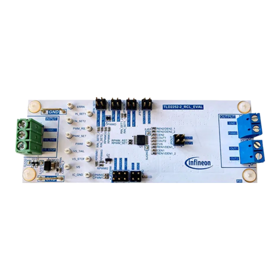
The purpose of the TLD2252-2EP rear combination lamp evaluation board (TLD2252-2_RCL_EVAL) board is to
help designers evaluate the features and the performance of the TLD2252-2EP, a two-channel linear current
source LED driver for automotive LED lighting applications. TLD2252-2EP provides a simple and compact
solution for the implementation of a rear combination lamp (RCL).
This user manual provides the usage instructions of the TLD2252-2 _RCL_ EVAL board (schematic version S00,
PCB version P00).
Figure 1
TLD2252-2_RCL_EVAL board
Intended audience
Hardware engineers, system architects.
User Manual
Please read the Important Notice and Warnings at the end of this document
Rev.1.00
www.infineon.com
page 1 of 14
2020-12-03
Advertisement
Table of Contents

Subscribe to Our Youtube Channel
Summary of Contents for Infineon TLD2252-2EP
-
Page 1: About This Document
The purpose of the TLD2252-2EP rear combination lamp evaluation board (TLD2252-2_RCL_EVAL) board is to help designers evaluate the features and the performance of the TLD2252-2EP, a two-channel linear current source LED driver for automotive LED lighting applications. TLD2252-2EP provides a simple and compact solution for the implementation of a rear combination lamp (RCL). -
Page 2: Table Of Contents
LITIX™ Basic+ LED driver Application note regarding the main operating principles of the pulse width family: How to implement a modulation (PWM) engine integrated into the LITIX™ Basic+ TLD2252-2EP, rear combination lamp TLD2141-3EP and TLD2142-1EP, and how to build a rear combination lamp (RCL) using PWM LITIX™... -
Page 3: Tld2252-2_Rcl_Eval Description
TLD2252-2_RCL_EVAL description The TLD2252-2_RCL_EVAL is an evaluation board equipped with one LITIX™ Basic+ TLD2252-2EP and on-board LEDs for easy evaluation of an RCL application when realized with use of the TLD2252-2EP pulse width modulation (PWM) engine. The board can be used within the typical automotive voltage range, 8 V to 16 V. It gives the user the freedom to evaluate all of the TLD2252-2EP features and possible configurations by setting the necessary jumpers accordingly. -
Page 4: Connectors And Jumpers
LITIX™ Basic+ TLD2252-2EP Ground OUTPUT Ground PWMO LITIX™ Basic+ TLD2252-2EP PWM signal to drive other LITIX™ Basic devices OUT1 External load for output channel 1, OUT1 OUT2 External load for output channel 2, OUT2 The TLD2252-2_RCL_EVAL board jumpers are described in Table 3. -
Page 5: On-Board Load
TLD2252-2EP rear combination lamp evaluation board User Manual TLD2252-2_RCL_EVAL description Jumper Description and configuration Open: when a fault is detected both channels will switch off • CD: when a fault is detected both channels will switch off after a delay time t •... -
Page 6: Test Points
TLD2252-2EP rear combination lamp evaluation board User Manual TLD2252-2_RCL_EVAL description Test points The TLD2252-2_RCL_EVAL board is equipped with several test points and two ground terminals for easy monitoring of significant voltages, Figure 4. Figure 4 Test points and ground terminals... -
Page 7: Quick Start
TLD2252-2EP rear combination lamp evaluation board User Manual Quick start Quick start Connect a voltage source to VS_TAIL or VS_STOP and GND, typical 8 V to 16 V • Select the output current by placing jumpers at JPN_SET1 and JPN_SET2 •... -
Page 8: Schematics, Layout And Bill Of Material
Schematics, layout and bill of material Schematics, layout and bill of material For the calculation of the external components required for the LITIX™ Basic+ TLD2252-2EP and used on the TLD2252-2_RCL_EVAL board refer to the following documentation: LITIX™ Basic+ TLD2252-2EP data sheet •... - Page 9 TLD2252-2EP rear combination lamp evaluation board User Manual Schematics, layout and bill of material Figure 6 Schematic of TLD2252-2_RCL_EVAL board – power supply Figure 7 Schematic of TLD2252-2_RCL_EVAL board – TLD2252-2EP User Manual 9 of 14 Rev.1.00 2020-12-03...
-
Page 10: Layout
TLD2252-2EP rear combination lamp evaluation board User Manual Schematics, layout and bill of material Figure 8 Schematic of TLD2252-2_RCL_EVAL board – on-board LED load Layout Figure 9 and Figure 10 show the layout of the TLD2252-2_RCL_EVAL board. Figure 9 Layout of TLD2252-2_RCL_EVAL board – top layer... -
Page 11: Bill Of Materials
TLD2252-2EP rear combination lamp evaluation board User Manual Schematics, layout and bill of material Figure 10 Layout of TLD2252-2_RCL_EVAL board – bottom layer Bill of materials Table 5 shows theTLD2252-2_RCL_EVAL board bill of material. Table 5 Bill of material Designator... -
Page 12: Pcb Design Data
TLD2252-2EP rear combination lamp evaluation board User Manual Schematics, layout and bill of material Designator Value Manufacturer Manufacturer order number REN1/DEN1_2, 3.6k Yageo AC0603FR-073K6L REN2/DEN2_2, RPWMI2 RERRN Yageo AC0603JR-0720KL RIN_SET1_1 36.5k Vishay CRCW060336K5FK RIN_SET1_2, RIN_SET2_2, RPWMO1, 7.32k Vishay CRCW06037K32FK RPWMO2 RIN_SET2_1 14.7k... -
Page 13: Revision History
TLD2252-2EP rear combination lamp evaluation board User Manual Revision history Revision history Date of release Description of changes Document version Rev.1.00 2020-12-03 Initial release User Manual 13 of 14 Rev.1.00 2020-12-03... - Page 14 Infineon Technologies hereby disclaims dangerous substances. For information on the types © 2020 Infineon Technologies AG. any and all warranties and liabilities of any kind in question please contact your nearest Infineon All Rights Reserved. (including without limitation warranties of non- Technologies office.


Need help?
Do you have a question about the TLD2252-2EP and is the answer not in the manual?
Questions and answers