Advertisement
Quick Links
!
DO NOT RETURN
TO THE STORE!
If you discover missing or damaged parts,
or if you have questions about the building process,
please reach out to us directly for the fastest service.
24/7 Support
help.backyardproducts.com
Call a Recruiter Today! 734-365-7000
Flexible schedule
*based on number of completed installations
STOP
Answers to frequently
asked questions
Technical assistance and
how-to videos
Submit a help request
Request replacement parts
Did you enjoy building your shed?
JOIN OUR TEAM
AND MAKE UP TO $1,500/WEEK*
No selling,
just building
Business Hours
(734) 242-6900
Monday - Friday ........... 8:00am - 6:00pm EST
Saturday - Sunday .................................Closed
Bonus incentives
available
16835-W
Advertisement

Related Manuals for Backyard Products 16835-W


Summary of Contents for Backyard Products 16835-W
- Page 1 16835-W STOP DO NOT RETURN TO THE STORE! If you discover missing or damaged parts, or if you have questions about the building process, please reach out to us directly for the fastest service. 24/7 Support Business Hours help.backyardproducts.com (734) 242-6900 Answers to frequently Monday - Friday ...
- Page 2 (This page intentionally left blank.)
-
Page 3: Assembly Manual
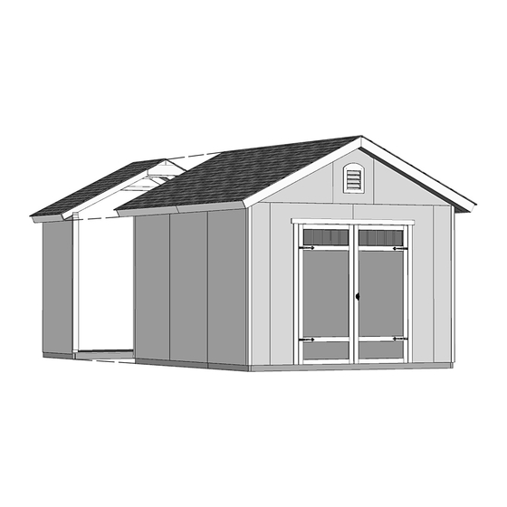
Backyard Products, LLC 16835-W 08/15/2022 ASSEMBLY MANUAL 1000 Ternes Drive Monroe, MI 48162 GABLE 10' x 12' (304,8 x 365,8 cm) BUILDING SIZE ACTUAL FLOOR SIZE 10' x 12' (304,8 x 365,8 cm) BASE MODEL 10' x 12' (304,8 x 365,8 cm) - Page 4 TOOLS Required Optional Phillips ❑ Tool Belt/ ❑ Utility Knife ❑ Screwdriver Nail Pouch Shingle Blades ❑ Drill / Driver ❑ Caulk Gun ❑ 1/8" Drill Bit ❑ Tin Snips ❑ 1/4" Drill Bit ❑ (for drip edge) 5/16" Drill Bit ❑...
-
Page 5: Additional Materials
ADDITIONAL MATERIALS FOUNDATION OR FLOOR MATERIALS • This shed does not include any floor or leveling materials. • See the FLOOR LEVELING section on page 10 for recommended methods and suggested materials to properly level your floor, as this will vary depending on your specific site. REINFORCED WOOD FLOOR FRAME (OPTIONAL) IMPORTANT! Depending on your specific use you may want to construct a heavy duty floor frame by adding additional floor joists (shown below as shaded). -
Page 6: Optional Materials
ADDITIONAL MATERIALS COMPLETING YOUR SHED You will need these additional materials: 10x12' 10x16' ALL SIZES 3-TAB SHINGLES (Bundles)....PAINT FOR TRIM ......2 Quarts Use 100% acrylic latex exterior paint. PAINT FOR SIDING (Gallons)....CAULK ...10x12 - 3 Tubes ...10x16 - 4 Tubes Use 100% acrylic latex exterior paint. -
Page 7: Parts List
PARTS IDENTIFICATION AND SIZES WOOD SIZE CONVERSION CHART Part identification letters are stamped on some parts. Treated lumber is stamped: Nominal Board Size Actual Size 2 x 4 ....1-1/2" x 3-1/2" (3,8 x 8,9 cm) 1 x 4 ....3/4" x 3-1/2" (1,9 x 8,9 cm) 2 x 3 ....1-1/2"... - Page 8 ROOF PANELS Roof panels are 7/16" (1,1 cm) thick. NOTE: Panel parts are not stamped. 7/16 x 8-5/8 x 27-1/4" (1,1 x 21,9 x 69,2 cm) 7/16 x 47-7/8 x 48" (1,1 x 121,6 x 121,9 cm) 7/16 x 8-5/8 x 48" (1,1 x 21,9 x 121,9 cm) 7/16 x 27-1/4 x 48"...
- Page 9 FASTENER/HARDWARE BAG x100 1-1/2" (3,8 cm) x255 2" (5,1 cm) x175 3" (7,6 cm) 2" (5,0 cm) 1-5/8" (4,1 cm) NOTE: If you are using a nail gun, nails 3/4" (1,9 cm) may be used where screws are shown for quicker assembly. 1"...
- Page 10 PARTS IDENTIFICATION AND SIZES Part identification is WOOD SIZE CONVERSION CHART stamped on some parts. Nominal Board Size Actual Size 2 x 4 ....1-1/2" x 3-1/2" (3,8 x 8,9 cm) 1 x 4 ....3/4" x 3-1/2" (1,9 x 8,9 cm) 2 x 3 ....1-1/2"...
- Page 11 CONCRETE FOUNDATION If you choose to install your kit on a concrete slab refer to the diagram below. Attach the sill plates on the foundaton as shown, and continue on to page 14. Treated Sill Plate Caulk between sill plate and concrete.
- Page 12 OPTIONAL WOOD FRAME FLOOR LEVELING OPTIONS There are multiple ways to level your floor frame. Our recommended leveling method is shown below. Leveling materials are not included in this kit. PREFERRED METHOD - 4x4 TREATED RUNNERS (Typical for 10' x 12' Kit) Runners are generally 12"...
- Page 13 LEVELING & SQUARING THE FLOOR FRAME (Not Included) LEVEL AND SQUARE FLOOR FRAME Before attaching floor decking, it is important to level and square the floor frame. A level and square floor frame is required to correctly construct your shed. See page 10 for the preferred foor leveling method.
- Page 14 Ensure that the foor frame is level after installing foor panels. Re-level if necessary. • The foor should used as a stable work surface for wall construction. • Organize your assembly procedure during the build process to avoid over-handling of the walls. HINT: GABLE WALL EAVE WALL...
-
Page 15: Rafter Assembly
RAFTER ASSEMBLY PARTS REQUIRED: 3" (7,6 cm) 2 x 4 x 4-7/8" (5,1 x 10,2 x 12,4 cm) Build a rafter jig using the floor and (2) CLA parts. ¸ BEGIN Secure (1) CLA flush to the floor deck with (2) 3" screws (Fig. A). Measure over 120-3/4"... - Page 16 RAFTER ASSEMBLY 10x12' 10x16' PARTS REQUIRED: OSB OR WOOD GRAIN 2 x 4 x 75-1/4" (5,1 x 10,2 x 191,1 cm) x130 x174 2" (5,1 cm) 1-5/8" (4,1 cm) ¸ BEGIN Place (2) rafters ECN into the jig, as shown. Press ECN firmly against the outside of CLA's, as shown (Fig.
- Page 17 WALL INDEX Create your own style of shed. Choose your door location. Use this guide to find the corresponding wall construction and installlation pages. As another option, eave walls with doors can be reversed during assembly. IMPORTANT! Build your door header before building any walls (see page 16). 10' x 12' Door on gable wall 10' x 12' Door on eave wall After assembling the walls for your 10' x 12' shed,...
- Page 18 DOOR HEADER Assemble this door header before building any walls! Any wall with a door will require this assembly. PARTS REQUIRED: 3" (7,6 cm) 2 x 4 x 67" (5,1 x 10,2 x 170,2 cm) 7/16 x 3-1/4 x 66-3/4" (1,1 x 8,3 x 170,2 cm) BEGIN Place (1) AM and OSB end-to-end on flat surface, flush in middle.
- Page 19 WALL PANEL INSTALLATION HINTS & EXAMPLES PARTS REQUIRED: 2" (5,1 cm) TEMP. SPACER 3/4" GAUGE BLOCK 3/8 x 48 x 84" (1 x 121,9 x 213,4 cm ) Ensure your wall is square by installing one panel and squaring frame. Install all wall panels with the primed side facing up.
- Page 20 10' WALL - 01 PARTS REQUIRED: 2 x 4 x 6-1/2" (5,1 x 10,2 x 16,5 cm) 3" (7,6 cm) x2 SL 2 x 4 x 36" (5,1 x 10,2 x 91,4 cm) 3" (7,6 cm) 2 x 4 x 68" (5,1 x 10,2 x 172,7 cm) 2 x 4 x 78-1/2"...
- Page 21 10' WALL 01 PARTS REQUIRED: 3" (7,6 cm) x158 2" (5,1 cm) 11-7/8" x 84" (30,2 x 213,4 cm) Temporary Brace 69" (75,3 cm) Door Stiffener Install the left panel 1-1/2" 1-1/2" from the top plate. Flush (3,8 cm) 3/4" BEGIN HERE Use a 2x4 spacer for (1,9 cm)
- Page 22 10' WALL 02 PARTS REQUIRED: 3" (7,6 cm) 2 x 4 x 24" (5,1 x 10,2 x 61 cm) 2 x 4 x 78-1/2" (5,1 x 10,2 x 199,4 cm) 2 x 4 x 96" (5,1 x 10,2 x 243,8 cm) BEGIN Arrange parts on edge on floor as shown.
- Page 23 10' WALL 02 PARTS REQUIRED: x136 2" (5,1 cm) 48 x 84" 23-7/8" x 84" (121,9 x 213,4 cm ) (60,6 x 213,4 cm ) 1-1/2" (3,8 cm) 3/4" BEGIN HERE Install 48" x 84" panel 1-1/2" (1,9 cm) from the top plate. Use a 2x4 spacer for consistent measurement.
- Page 24 10' WALL 03 PARTS REQUIRED: 3" (7,6 cm) x2 SL 2 x 4 x 36" (5,1 x 10,2 x 91,4 cm) 2 x 4 x 78-1/2" (5,1 x 10,2 x 199,4 cm) 2 x 4 x 84" (5,1 x 10,2 x 213,4 cm) BEGIN Orient parts on edge on floor as shown.
- Page 25 10' WALL 03 PARTS REQUIRED: x164 2" (5,1 cm) 48 x 84" (121,9 x 213,4 cm ) 11-7/8" x 84" (30,2 x 213,4 cm) 3/4" Install 48" x 84" panel BEGIN HERE 1-1/2" (1,9 cm) (3,8 cm) 1-1/2" from the top plate. Use a 2x4 spacer for consistent measurement.
- Page 26 12' WALL 04 PARTS REQUIRED: 3" (7,6 cm) 2 x 4 x 44-3/8" (5,1 x 10,2 x 112,7 cm) 2 x 4 x 92-5/8" (5,1 x 10,2 x 235,3 cm) 2 x 4 x 68-1/2" (5,1 x 10,2 x 174 cm) 2 x 4 x 78-1/2"...
- Page 27 12' WALL 04 PARTS REQUIRED: x120 2" (5,1 cm) 48 x 84" (121,9 x 213,4 cm ) 3/4" BEGIN HERE 3-1/2" (1,9 cm) Install 48" x 84" panel (8,9 cm) 1-1/2" from the top plate. 1-1/2" (3,8 cm) Use a 2x4 spacer for consistent measurement.
- Page 28 12' WALL 05 If a workbench is being installed, see next page for alternate framing. PARTS REQUIRED: 3" (7,6 cm) 2 x 4 x 6-1/2" (5,1 x 10,2 x 16,5 cm) 2 x 4 x 44-3/8" (5,1 x 10,2 x 112,7 cm) 3"...
- Page 29 12' WALL 05 If a workbench is being installed, use this page for alternate framing. PARTS REQUIRED: 3" (7,6 cm) 2 x 4 x 6-1/2" (5,1 x 10,2 x 16,5 cm) 2 x 4 x 44-3/8" (5,1 x 10,2 x 112,7 cm) 3"...
- Page 30 12' WALL 05 PARTS REQUIRED: x120 2" (5,1 cm) 48 x 84" (121,9 x 213,4 cm ) 3-1/2" 1-1/2" (8,9 cm) Install the left panel 1-1/2" Flush (3,8 cm) 3/4" BEGIN HERE from the top plate. (1,9 cm) Use a 2x4 spacer for consistent measurement.
- Page 31 16' WALL 06 PARTS REQUIRED: 3" (7,6 cm) 2 x 4 x 44-3/8" (5,1 x 10,2 x 112,7 cm) 2 x 4 x 48" (5,1 x 10,2 x 121,9 cm) 2 x 4 x 68-1/2" (5,1 x 10,2 x 174 cm) 2 x 4 x 78-1/2"...
- Page 32 16' WALL 06 PARTS REQUIRED: x170 2" (5,1 cm) 48 x 84" (121,9 x 213,4 cm ) Install 48" x 84" panel 1-1/2" from the top plate. 3/4" BEGIN HERE (1,9 cm) 1-1/2" Use a 2x4 spacer (3,8 cm) for consistent measurement.
- Page 33 16' WALL 07 PARTS REQUIRED: 3" (7,6 cm) 2 x 4 x 6-1/2" (5,1 x 10,2 x 16,5 cm) 3" (7,6 cm) 2 x 4 x 48" (5,1 x 10,2 x 121,9 cm) 2 x 4 x 68" (5,1 x 10,2 x 172,7 cm) 2 x 4 x 44-3/8"...
- Page 34 16' WALL 07 PARTS REQUIRED: 3" (7,6 cm) x164 2" (5,1 cm) Temporary Brace 48 x 84" (121,9 x 213,4 cm ) 69" (75,3 cm) Door Stiffener 3-1/2" 1-1/2" Install the left panel Flush (8,9 cm) (3,8 cm) 1-1/2" from the top plate. 3/4"...
- Page 35 STANDING YOUR WALLS The following steps show how to stand and secure your walls for a 10' x 12' shed. These instructions are by default with the door on the 10' gable wall. For 10' x 16' steps, start on page 38. STANDARD: DOOR LOCATED ON 10' GABLE WALL...
- Page 36 10' WALL 02 INSTALLATION PARTS REQUIRED: 3" (7,6 cm) 69" (175,3 cm) Door Stiffener 3" (7,6 cm) 2" (5,1 cm) BEGIN 1-1/2" Center 10' wall on the 120" (304,8 cm) floor dimension. (3,8 cm) 1-1/2" (3,8 cm) overlap is to the top. Use OO as a temporary brace.
- Page 37 12' WALL 04 or 05 INSTALLATION PARTS REQUIRED 2" (5,1 cm) 3" (7,6 cm) 2" (5,1 cm) 1-1/2" (3,8 cm) 3" (7,6 cm) Fig. B BEGIN Place 12' wall centered on floor. 1-1/2" (3,8 cm) overlap is to the top. 2"...
- Page 38 12' WALL 04 INSTALLATION PARTS REQUIRED: 2" (5,1 cm) 3" (7,6 cm) 2" (5,1 cm) 3" (7,6 cm) 1-1/2" (3,8 cm) 1-1/2" BEGIN Fig. B (3,8 cm) Remove temporary brace OO from installed 10' wall. Place 12' wall centered on floor. 2"...
- Page 39 10' WALL 01 or 03 INSTALLATION PARTS REQUIRED 2" (5,1 cm) 3" (7,6 cm) 2" (5,1 cm) 1-1/2" (3,8 cm) 3" (7,6 cm) Fig. B BEGIN 2" (5,1 cm) Place 10' wall on floor centered between 12' walls. Screw Secure wall with 2" screws into top and bottom plates (Fig.
- Page 40 10' x 12' WALL DOUBLERS INSTALLATION PARTS REQUIRED: 3" (7,6 cm) x2 JBD 2 x 4 x 20-3/8" (5,1 x 10,2 x 51,8 cm) 2 x 4 x 48" (5,1 x 10,2 x 121,9 cm) 3" (7,6 cm) 2 x 4 x 92-5/8" (5,1 x 10,2 x 235 cm) 2 x 4 x 96"...
- Page 41 10' WALL 02 INSTALLATION PARTS REQUIRED: 3" (7,6 cm) 69" (175,3 cm) Door Stiffener 3" (7,6 cm) 2" (5,1 cm) BEGIN 1-1/2" Center 10' wall on the 120" (3,8 cm) (304,8 cm) floor dimension. 1-1/2" (3,8 cm) overlap is to the top. 3"...
- Page 42 16' WALL 06 or 07 INSTALLATION PARTS REQUIRED 2" (5,1 cm) 3" (7,6 cm) Temporary Brace 1-1/2" (3,8 cm) 2 x 4 x 96" (5,1 x 10,2 x 243,8 cm) 2" (5,1 cm) 3" (7,6 cm) Fig. B BEGIN Place 16' wall centered on floor. 2"...
- Page 43 16' WALL 06 INSTALLATION PARTS REQUIRED: 2" (5,1 cm) 3" (7,6 cm) Temporary Brace 2 x 4 x 96" (5,1 x 10,2 x 243,8 cm) BEGIN 1-1/2" (3,8 cm) Remove temporary brace OO from installed 10' wall. Place 16' wall centered on floor. 3"...
- Page 44 16' WALL 06 INSTALLATION PARTS REQUIRED: 3" (7,6 cm) 2" (5,1 cm) 3" (7,6 cm) 1-1/2" (3,8 cm) Nail lower edge of wall panels to floor frame with 2" nails spaced 6" apart. Angle nails into floor frame (Fig. C). 3"...
- Page 45 10' WALL 01 or 03 INSTALLATION PARTS REQUIRED 2" (5,1 cm) 3" (7,6 cm) 2" (5,1 cm) 3" (7,6 cm) 1-1/2" (3,8 cm) Fig. B BEGIN 2" (5,1 cm) Place 10' wall on floor centered between 16' walls. Screw Secure wall with 2" screws into top and bottom plates (Fig.
- Page 46 10' x 16' WALL DOUBLERS INSTALLATION PARTS REQUIRED: 3" (7,6 cm) x2 JBD 2 x 4 x 20-3/8" (5,1 x 10,2 x 51,8 cm) 2 x 4 x 48" (5,1 x 10,2 x 121,9 cm) 3" (7,6 cm) 2 x 4 x 92-5/8" (5,1 x 10,2 x 235 cm) 2 x 4 x 96"...
- Page 47 RAFTER INSTALLATION 10x12' 10x16' PARTS REQUIRED: Two-Gusset Preassembled One-Gusset Preassembled 3" (7,6 cm) BEGIN Align rafters over the wall studs. Check that you have the measurements shown. Secure rafters with (2) 3" screws angled at each end (Fig. A, Fig. B). Secure rafters on opposite side.
- Page 48 GABLE UNITS PARTS REQUIRED: 1-1/2" (3,8 cm) 2 x 4 x 23-1/4" (5,1 x 10,2 x 59,1 cm) Install gable panels with the primed side facing up. BEGIN Place middle panel on (2) UV. Arrange parts to measurements shown. Secure panel with 1-1/2" nails spaced 6" apart along edge. Check measurements as you build the gable unit.
- Page 49 GABLE UNITS PARTS REQUIRED: 3" (7,6 cm) 2 x 4 x 4-7/8" (5,1 x 10,2 x 12,4 cm) 2 x 3 x 75-1/4" (5,1 x 7,6 x 191,1 cm) BEGIN Arrange parts as shown (Fig. A). You will build (4) assemblies (Fig. B). Arrange, measure and mark locations of (3) CLA as shown place ECA on top.
- Page 50 GABLE UNITS PARTS REQUIRED: 1-5/8" (4,1 cm) x2 Gable Assemblies x2 Ladder Assemblies Arrange gable and ladder assemblies as shown (Fig. E). You will build (2) complete assemblies. Ensure gable panels are flush at peak of ladder and flush along top edge of ladder assembly.
- Page 51 GABLE UNITS PARTS REQUIRED: 3" (7,6 cm) 2" (5,1 cm) x2 Gable Units BEGIN Measure 1-1/2" down from wall doubler and mark at each side as shown. Set gable unit on top plate. Fasten with (1) 2" nail on each side. BE SURE GABLE IS CENTERED ON WALL BEFORE NAILING.
- Page 52 GABLE UNITS PARTS REQUIRED: 3" (7,6 cm) Secure gable unit frame to end rafter with 3" screws, evenly spaced. Angle screws if neccessary END RAFTER 3" (7,6 cm) Screws Repeat all steps to install the 2nd gable unit. FINISH Your (2) gable units are now installed...
- Page 53 10' x 12' ROOF PANELS PARTS REQUIRED: 2" (5,1 cm) 3/4" GAUGE BLOCK 7/16 x 48 x 96" (1,1 x 121,9 x 243,8 cm) Install all roof panels with the rough side (painted grid lines) facing up. Roof panels may cause serious injury until securely fastened. BEGIN Install (1) 48"...
- Page 54 10' x 12' ROOF PANELS PARTS REQUIRED: 2" (5,1 cm) 7/16 x 27-1/4 x 48" (1,1 x 69,2,9 x 121,9 cm) Install (1) 27-1/4" x 48" panel flush to installed panel, and the panel flush to rafter ends (Fig. B). Secure panel with (2) 2"...
- Page 55 10' x 12' ROOF PANELS PARTS REQUIRED: 7/16 x 27-1/4 x 48" (1,1 x 69,2,9 x 121,9 cm) 2" (5,1 cm) 3/4" GAUGE 7/16 x 47-7/8 x 48" BLOCK (1,1 x 121,6 x 121,9 cm) 3/4" (1,9 cm) Install (1) 47-7/8" x 48" roof panel flush to installed panels.
- Page 56 10' x 12' ROOF PANELS PARTS REQUIRED: x275 2" (5,1 cm) 7/16 x 8-5/8 x 48" 7/16 x 8-5/8 x 27-1/4" (1,1 x 21,9 x 121,9 cm) (1,1 x 21,9 x 69,2 cm) Flush Install (2) 8-5/8" x 27-1/4" panels flush to lower ends of gable frame and rafter, and flush to outside 8-5/8"...
- Page 57 10' x 16' ROOF PANELS PARTS REQUIRED: 2" (5,1 cm) 3/4" GAUGE BLOCK 7/16 x 48 x 96" (1,1 x 121,9 x 243,8 cm) Install all roof panels with the rough side (painted grid lines) facing up. Roof panels may cause serious injury until securely fastened. BEGIN Install (1) 48"...
- Page 58 10' x 16' ROOF PANELS PARTS REQUIRED: 2" (5,1 cm) 7/16 x 47-7/8 x 48" 7/16 x 27-1/4 x 48" (1,1 x 121,6 x 121,9 cm) (1,1 x 69,2,9 x 121,9 cm) Install (1) 27-1/4" x 48" panel flush to installed panel, and the panel flush to rafter ends (Fig.
- Page 59 10' x 16' ROOF PANELS PARTS REQUIRED: 7/16 x 27-1/4 x 48" (1,1 x 69,2,9 x 121,9 cm) 2" (5,1 cm) 3/4" GAUGE 7/16 x 47-7/8 x 48" BLOCK (1,1 x 121,6 x 121,9 cm) 3/4" (1,9 cm) Install (1) 47-7/8" x 48" roof panel flush to installed panels.
- Page 60 10' x 16' ROOF PANELS PARTS REQUIRED: x317 2" (5,1 cm) 7/16 x 8-5/8 x 48" 7/16 x 8-5/8 x 27-1/4" (1,1 x 21,9 x 121,9 cm) (1,1 x 21,9 x 69,2 cm) Flush Install (2) 8-5/8" x 27-1/4" panels flush to lower ends of gable frame and rafter, and flush to outside 8-5/8"...
- Page 61 GABLE SOFFIT PANELS PARTS REQUIRED: 2" (5,1 cm) 3/8 x 7-7/8 x 73-5/16" (1 x 20 x 186,2 cm) Install all soffit panels with the primed side facing out. BEGIN Position right 73-5/16" soffit panel flush to gable panel and flush to gable end. Secure with 2"...
- Page 62 EAVE SOFFIT PANELS 10'x12' PARTS REQUIRED: 2" (5,1 cm) 3/8 x 5-7/8 x 72-3/4" (1 x 14,9 x 184,8 cm) Install all soffit panels with the primed side facing out. BEGIN Install (2) 72-3/4" soffit panels flush at seamm (Fig A). Secure with 2"...
- Page 63 EAVE SOFFIT PANELS 10'x16' PARTS REQUIRED: 2" (5,1 cm) 3/8 x 5-7/8 x 72-3/4" (1 x 14,9 x 184,8 cm) 3/8 x 5-7/8 x 48" (1 x 14,9 x 121,9 cm) Install all soffit panels with the primed side facing out. BEGIN Install (1) 48"...
- Page 64 GABLE FASCIA PARTS REQUIRED: 2" (5,1 cm) Painted Red 3/8 x 4-3/4 x 75-7/8" (1 x 12,1 x 192,7 cm) Painted Green 3/8 x 4-3/4 x 75-7/8" (1 x 12,1 x 192,7 cm) Install all trim with the primed side facing out. BEGIN Position fascia with primed side out and flush to peak and roof panels as shown (Fig.
- Page 65 EAVE SIDE FASCIA 10'x12' PARTS REQUIRED: 2" (5,1 cm) 3/8 x 4-3/4 x 80-5/8" (1 x 12,1 x 204,8 cm) Install all trim with the primed side facing out. BEGIN Install (2) 4-3/4" x 80-5/8" fascia boards flush with roof panels and flush to center seam (Fig.
- Page 66 DOORS PARTS REQUIRED: 3" (7,6 cm) 1-5/8" (4,1 cm) 1 x 3 x 5" (2,5 x 7,6 x 12,7 cm) Door Stiffener 69" (175,3 cm) ¸ BEGIN Arrange parts as shown on flat surface. 3/8" offset is to top. Look for red (right) and green (left) on hinge board. Attach temporary support OO with 3"...
- Page 67 DOORS PARTS REQUIRED: 3" (7,6 cm) 69" Door Stiffener (175,3 cm) Install temporary support OO as a ledger board flush under wall panels for doors to rest on. Secure with (2) 3" screws (Fig. A) . Flush against wall panels. Fig.
- Page 68 DOOR TRIM PARTS REQUIRED: 3/4" (1,9 cm) x11 2" (5,1 cm) Bagged seperately / special coating 19/32 x 3 x 26-5/8" (1,5 x 7,6 x 67,6 cm) 64" Metal Threshold 3/4" (1,9 cm) 19/32 x 3 x 72" (1,5 x 7,6 x 183 cm) BEGIN Secure door trim from inside using 3/4"...
- Page 69 DOOR TRANSOM WINDOWS PARTS REQUIRED: 3/4" (1,9 cm) Transom Window ¸ BEGIN Apply high quality exterior-grade caulk behind frame near edge before installing to seal window. You must caulk completely around window frame and all exposed door panel edges and trim to validate your warranty. Use a paintable exterior rated caulk.
- Page 70 DOOR STIFFENERS PARTS REQUIRED: 2" (5,1 cm) 69" Door Stiffener (175,3 cm) BEGIN Center OO vertically on the left door in the door opening flush with the edge of door (Fig. A). Secure with (7) 2" screws through outside trim into OO (Fig. B) Repeat steps to install OO on right door.
-
Page 71: Door Hardware
DOOR HARDWARE PARTS REQUIRED: 1/2" (13 mm) Drill Bit 1/4" (6 mm) Drill Bit 1" (2,5 cm) BEGIN Measure and mark location of hole on outside of right door as shown (Fig. A) . Pre-drill hole with 1/4" drill. Re-drill hole with 1/2" drill (Fig. B) . Keep drilled hole square to trim to avoid breaking edge of door stiffener OO. - Page 72 DOOR HARDWARE PARTS REQUIRED: Handle (locking) with Screws 1-1/4” x2 1/2" (13 mm) Drill Bit 1/4" (6 mm) Drill Bit Secure handle with 1-1/4" screws, as shown. Screw 1-1/4" Wood Screws...
- Page 73 DOUBLE DOOR HARDWARE PARTS REQUIRED: 1-1/4 (3,2 cm) 3/8" BIT (9,5 mm) ¸ BEGIN Flush and center top spring bolt at the top of OO (Fig. A). Secure with (4) 1-1/4" screws. Mark spring bolt pin location on over door frame. Drill a 1-1/2" deep hole using a 3/8" drill bit. Flush and center bottom spring bolt to bottom of OO (Fig.
- Page 74 CORNER TRIM PARTS REQUIRED: 2" (5,1 cm) 3/8 x 1-3/4 x 82-1/2" (1 x 4,4 x 209,6 cm) 3/8 x 1-3/4 x 81-7/8" (1 x 4,4 x 208 cm) ¸ BEGIN Install gable end 82-1/2" corner trim flush to gable panel (Fig. A) and flush with eave wall panel (Fig.
- Page 75 COLLAR TIE INSTALLATION 10x12' 10x16' PARTS REQUIRED: 1 x 3 x 72" (5,1 x 10,3 x 183 cm) 2" (5,1 cm) BEGIN Fig. A Install collar tie to the rafter with (3) 3" nails at each end (Fig. A). Flush to roof panel 2"...
- Page 76 GABLE VENTS PARTS REQUIRED: #8 x 1" (2,5 cm) Pan Head Screws ¸ BEGIN Locate vent in the gable wall, as shown. Locate vent in the gable wall, as shown. Seal vent from behind with exterior grade caulk before installing. Secure vent with 1"...
- Page 77 PAINT & CAULK - NOT INCLUDED - • Use acrylic latex caulk that is paintable. Caulk at all horizontal and vertical seams, between the trim and walls, and all around the door trim. • Use a high quality exterior acrylic latex paint. When painting your building, there are a few key areas that can be easily overlooked that must be painted: •...
- Page 78 SHINGLES - NOT INCLUDED - • Follow directions provided by manufacturer and these instructions. Familiarize yourself with a 3-Tab Shingle. Notch Notch SHINGLE NAIL PATTERN 1/2 " 1" Sealing Str 1" (1,3 cm) (2,5 cm) (2,5 cm) Half A Rain Slot Full Rain Slot NAILS NEVER DRIVE FASTENERS INTO OR ABOVE SEALING STRIPS.
- Page 79 SHINGLES continued... Beginning at front of shed, install first row of shingles with notch at 1" past roof edge or flush with drip edge. Roof Deck FRONT OF BACK OF SHED SHED 1" (2,5 cm) Flush with starter row. Notch - or - Drip Edge Flush with starter row.
- Page 80 SHINGLES continued... Continue installing rows of shingles to the peak. At the peak make sure there is a maximum of 5" or less to the rain slot, as shown below. If shingles overlap at ridge cut to peak with a utility knife. 5"...
- Page 81 SHINGLES - RIDGE CAP • You will finish off the top of the roof with a ridge cap made from shingles. BEGIN Cut shingles into THREE pieces. Hint: Use cut-off pieces first. 2" 2" (5 cm) (5 cm 2" 2" 2"...
- Page 82 SHINGLES - RIDGE CAP continued... Continue installing ridge cap to back of roof. Make sure there is 4" between the shingle-color and edge of shingles. 4" (10 cm) Trim cap off fush to shingles When you have 4" minimum of shingle color cut one piece to cap your roof. Cut at top of rain slot.
- Page 83 16835-W 10' x12' Order Form CATEGORY PART DESCRIPTION PART SIZE PART ITEM # BUILDING QTY. PART ID 2 X 3 Window Crippler 2 X 3 X 8" SOFFIT FILLER Q 08000000000 Overhang Blocking & Gable Framing 2 X 4 X 4-7/8" OVERHANG BLOCK O 04140000000 Sidewall Top &...
- Page 84 LIMITED CONDITIONAL WARRANTY* Backyard Storage Solutions, LLC warrants the following: Every product is warranted from defects in workmanship and manufacturing for 1 year. All accessories, hardware and metal components are warranted for 2 years. All Oriented Strand Board (OSB) is warranted for 2 years Siding and Trim is warranted for 10 years.