Advertisement
Quick Links
!
DO NOT RETURN
TO THE STORE!
If you discover missing or damaged parts,
or if you have questions about the building process,
please reach out to us directly for the fastest service.
24/7 Support
help.backyardproducts.com
Call a Recruiter Today! 734-365-7000
Flexible schedule
*based on number of completed installations
STOP
Answers to frequently
asked questions
Technical assistance and
how-to videos
Submit a help request
Request replacement parts
Did you enjoy building your shed?
JOIN OUR TEAM
AND MAKE UP TO $1,500/WEEK*
No selling,
just building
Business Hours
(734) 242-6900
Monday - Friday ........... 8:00am - 6:00pm EST
Saturday - Sunday .................................Closed
Bonus incentives
available
16162
Advertisement

Subscribe to Our Youtube Channel
Related Manuals for Backyard Products HANDY HOME PRODUCTS MARCO Series


Summary of Contents for Backyard Products HANDY HOME PRODUCTS MARCO Series
- Page 1 16162 STOP DO NOT RETURN TO THE STORE! If you discover missing or damaged parts, or if you have questions about the building process, please reach out to us directly for the fastest service. 24/7 Support Business Hours help.backyardproducts.com (734) 242-6900 Answers to frequently Monday - Friday ...
- Page 2 (This page intentionally left blank.)
-
Page 3: Assembly Manual
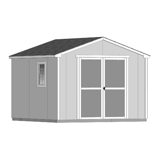
16162 11/09/2022 ASSEMBLY MANUAL A Backyard Products Company MARCO SERIES PRINCETON 10' x 10' (305 x 305 cm) ACTUAL FLOOR SIZE IS 120" x 116-5/8" (305 x 296 cm) KEEP THIS MANUAL FOR FUTURE REFERENCE I M PO RTANT! READ INSTRUCTIONS THOROUGHLY PRIOR TO BEGINNING ASSEMBLY. - Page 4 TOOLS Required Optional K Phillips K Tool Belt/ K Utility Knife Screwdriver Nail Pouch K Shingle Blades K Drill / Driver K Tin Snips K 3/8" Drill Bit K Caulk Gun (for drip edge) K #2 Philips Drive Bit K Chalk Line K Hammer K Paint Tools K Level...
-
Page 5: Additional Materials
ADDITIONAL MATERIALS FOUNDATION OR FLOOR MATERIALS • This kit includes a complete floor. • This shed kit does not include ANY leveling materials. • See the FLOOR LEVELING section on page 7 for recommended methods and suggested materials to properly level your floor, as this will vary depending on your specific site. -
Page 6: Parts List
PARTS IDENTIFICATION AND SIZES WOOD SIZE CONVERSION CHART Part identification Treated lumber is stamped: Nominal Board Size Actual Size is stamped on some parts. 2 x 4 ....1-1/2" x 3-1/2" (3,8 x 8,9 cm) 1 x 4 ....3/4" x 3-1/2" (1,9 x 8,9 cm) 2 x 3 ....1-1/2"... - Page 7 WALL PANELS and DOORS 3/8 x 23-7/8 x 72" 3/8 x 48 x 72" 3/8 x 48 x 72" LEFT DOOR RIGHT DOOR (1 x 61 x 183 cm) (1 x 122 x 183 cm) (1 x 122 x 183 cm) ROOF PANELS Roof panels are 7/16"...
- Page 8 FLOOR PANELS Floor panels are 5/8" (1,6 cm) thick. 23-7/8 x 23-7/8" (61 x 61 cm) 23-7/8 x 92-5/8" (61 x 235,3 cm) 23-7/8 x 96" (61 x 244 cm) 48 x 92-5/8" (122 x 235,3 cm) WINDOW, VENTS and RAMPS 1/2"...
- Page 9 FLOOR LEVELING OPTIONS There are multiple ways to level your floor frame. Our recommended leveling method is shown below. Leveling materials are not included in this kit. PREFERRED METHOD - 4x4 TREATED RUNNERS 4x4 Runners (not included). Measurements to • 3" Screw angled into 4x4. centers of 4x4's.
- Page 10 CONCRETE FOUNDATION Your kit contains all materials to construct a wooden floor. If you choose to install your kit on a concrete slab, refer to the diagram below. Treated Sill Plate Caulk between sill plate and concrete. 3-1/2" (8,9 cm) 4"...
- Page 11 FLOOR FRAME PARTS REQUIRED: 3" (7,6 cm) 2 x 4 x 21" (5 x 10 x 58,3 cm) TREATED NOTE: Look for Stamp. 2 x 4 x 48" (5 x 10 x 122 cm) TREATED 2 x 4 x 72" (5 x 10 x 183 cm) TREATED You will build two floor sections.
- Page 12 FLOOR FRAME PARTS REQUIRED: NOTE: Look for Stamp. 3" (7,6 cm) 2 x 4 x 48" (5 x 10 x 122 cm) TREATED 2 x 4 x 72" (5 x 10 x 182,9 cm) TREATED 2 x 4 x 89-1/2" (5 x 10 x 227,3cm) TREATED Arrange parts as shown on flat surface.
- Page 13 FLOOR FRAME PARTS REQUIRED: 3" (7,6 cm) Fasten fl oor sections together, as shown. Secure with 3" nails. Flush Flush Stagger nail pattern. 116-1/2" (295,9 cm) 120" (304,8 cm) FINISH Your fl oor frame is now assembled. Proceed to level and square frame.
- Page 14 LEVEL AND SQUARE FLOOR FRAME Before attaching fl oor decking, it is important to level and square the fl oor frame. A level and square fl oor frame is required to correctly construct your shed. BEGIN See page 7 for the preferred fl oor leveling method. Use level and check the frame is level before applying fl oor panels.
- Page 15 FLOOR PANELS PARTS REQUIRED: 2" (5,1 cm) 5/8 x 48 x 92-1/2" 3/4" GAUGE (1,6 x 121,9 x 235 cm) BLOCK Ensure your wall frame is square by installing one panel and squaring frame. Install panels with rough side up (painted grid lines). BEGIN Install (1) 48"...
- Page 16 FLOOR PANELS PARTS REQUIRED: x195 5/8 x 23-7/8 x 23-7/8" 2" (5,1 cm) (1,6 x 60,6 x 60,6 cm) 5/8 x 48 x 92-1/2" 5/8 x 23-7/8 x 96" 3/4" GAUGE 5/8 x 23-7/8 x 92-1/2" BLOCK (1,6 x 121,9 x 235 cm) (1,6 x 121,9 x 235 cm) (1,6 x 60,6 x 243,8 cm) Continue installing the remaining panels in the following order:...
- Page 17 IMPORTANT! Ensure that the floor frame is level after installing floor panels. Re-level if necessary. • The floor should used as a stable work surface for wall construction. HINT: • Organize your assembly procedure during the build process to avoid over-handling of the walls. BACK WALL SIDE WALL SIDE WALL...
- Page 18 RAFTER ASSEMBLY JIG PARTS REQUIRED: 1-1/4" (3,2 cm) x8 1 x 3 x 7-1/2" (2,5 x 7,6 x 19 cm) Build a jig to ensure all rafters are assembled the same. ¸ BEGIN Mark a straight line on the fl oor from corner to corner. Secure blocks in place with 1-1/4"...
- Page 19 RAFTERS PARTS REQUIRED: 2" (5 cm) x96 6 x 24" (15 x 61 cm) 2 x 4 x 65-7/8" (5 x 10 x 167 cm) ¸ BEGIN Place (2) rafter halves CV on fl oor jig. You will assemble (4) rafters. Flush rafters at peak.
- Page 20 BACK WALL FRAME PARTS REQUIRED: 3" (7,6 cm) x6 2 x 3 x 46-1/4" (5 x 7,6 x 117,5 cm) 2 x 3 x 77" (5 x 7,6 x 196 cm) 2 x 3 x 94-1/2" (5 x 7,6 x 240 cm) BEGIN Arrange parts on edge on floor, as shown.
- Page 21 BACK WALL FRAME PARTS REQUIRED: 3" (7,6 cm) x2 2 x 3 x 46-1/4" (5 x 7,6 x 117,5 cm) Arrange parts on edge on fl oor, as shown. Secure with (2) 3" screws at middle connection. 48-3/4" 48-3/4" (124 cm) (124 cm) 1-1/2 (3,8 cm)
- Page 22 BACK WALL PANELS PARTS REQUIRED: 2" (5 cm) 3/4" GAUGE BLOCK 3/8 x 48 x 84" (1 x 122 x 213,4 cm) Install panels with the primed side facing up. BEGIN Install left panel on back frame, as shown. Use a 3/4" gauge block at edges of panel. Be sure to maintain 1"...
- Page 23 BACK WALL PANELS PARTS REQUIRED: 2" (5 cm) 3/4" GAUGE BLOCK 3/8 x 48 x 84" (1 x 122 x 213,4 cm) Install right panel on back frame, as shown. Use a 3/4" gauge block at edges of panel. Secure with 2" nails spaced 6" apart on edges and 12" apart inside panel. 6"...
- Page 24 WING WALL PANELS PARTS REQUIRED: 1-1/4" (3 cm) RIGHT LEFT 2 x 3 x 72" (5 x 7,6 x 183 cm) Wing Panels panels must be assembled with the primed side facing DOWN. You will assemble (2) right and (2) left wing walls. BEGIN Place OY on floor.
- Page 25 BACK WALL WING PANELS PARTS REQUIRED: 2" (5 cm) Pre-assembled LEFT Pre-assembled RIGHT Wing Panels panels must be installed with the primed side facing UP. Install wing wall assemblies onto back wall frame with bottom of panels fl ush to installed panels. Secure wing wall assemblies to back wall frame with 2"...
- Page 26 BACK WALL GABLE PANELS PARTS REQUIRED: 2" (5 cm) 3/4" GAUGE BLOCK RIGHT LEFT Gable panels must be assembled with the primed side facing up. BEGIN Install left gable panel onto frame, fl ush to installed panel. Maintain 3/4" on frame using a gauge block at edge of panel. Secure with 2"...
- Page 27 FRONT WALL FRAME PARTS REQUIRED: 3" (7,6 cm) 2 x 3 x 22-1/8" (5 x 7,6 x 56 cm) 2 x 3 x 77" (5 x 7,6 x 196 cm) 2 x 3 x 94-1/2" (5 x 7,6 x 240 cm) BEGIN Arrange parts on edge on fl oor.
- Page 28 FRONT WALL PANELS PARTS REQUIRED: 2" (5 cm) 3/4" GAUGE BLOCK 3/8 x 48 x 96" (1 x 122 x 244 cm) Install panels with the primed side facing up. BEGIN Install left panel on front frame, as shown. Use a 3/4" gauge block on edges of panel.Be sure to maintain 1" measurement between bottom edge of frame and bottom edge of panel (Fig.
- Page 29 FRONT WALL PANELS PARTS REQUIRED: 2" (5 cm) 3/4" GAUGE BLOCK 3/8 x 48 x 96" (1 x 122 x 244 cm) Install right panel on front frame, flush to installed panel. Use a 3/4" gauge block on edges of panel. Secure panel to frame with 2"...
- Page 30 FRONT WALL PANELS PARTS REQUIRED: 2" (5 cm) Pre-assembled LEFT Pre-assembled RIGHT Wing Panels panels must be installed with the primed side facing UP. Install wing wall assemblies onto front wall frame with bottom of panels fl ush to installed panels. Secure wing wall assemblies to back wall frame with 2"...
- Page 31 RIGHT SIDE WALL FRAME PARTS REQUIRED: 3" (7,6 cm) 2 x 3 x 46-1/4" (5 x 7,6 x 117,5 cm) 2 x 3 x 69" (5 x 7,6 x 175 cm) 2" x 3" x 70-1/4" (5 x 7,6 x 178,4 cm) 7/16 x 2-1/2 x 73-1/2"...
- Page 32 SIDE WALL FRAME - SOFFIT PARTS REQUIRED: 1-1/4" (3,2 cm) 3/8 x 5 x 21-1/4" (0,9 x 12,7 x 54 cm) 3/8 x 5 x 96" (0,9 x 12,7 x 244 cm) Install soffi t panels fl ush to wall top plate with primed side facing the frame (Fig A). Flush the panels at seam. Maintain soffi t panels fl ush to top plate (Fig A) and ensure 3/8"...
- Page 33 LEFT WALL PANELS PARTS REQUIRED: 2" (5 cm) 3/4" GAUGE BLOCK 3/8 x 48 x 72" (1 x 122 x 183 cm) Install panels with the primed side facing up. Ensure your wall frame is square by installing one panel and squaring frame. BEGIN Install first 48"...
- Page 34 LEFT SIDE WALL PANELS PARTS REQUIRED: 2" (5 cm) 3/4" GAUGE 3/8" x 48" x 72" 3/8 x 23-7/8 x 72" BLOCK (1 x 122 x 183 cm) (1 x 61 x 183 cm) Install next 48"x 72" panel fl ush to installed panel. Secure with 2"...
- Page 35 RIGHT WALL PANELS PARTS REQUIRED: 2" (5 cm) 3/4" GAUGE BLOCK 3/8 x 48 x 72" (1 x 122 x 183 cm) Install panels with the primed side facing up. Ensure your wall frame is square by installing one panel and squaring frame. BEGIN Install first 48"...
- Page 36 RIGHT SIDE WALL PANELS PARTS REQUIRED: 2" (5 cm) 3/8" x 48" x 72" 3/4" GAUGE 3/8 x 23-7/8 x 72" (1 x 122 x 183 cm) BLOCK (1 x 61 x 183 cm) Install 23-7/8"x 72" and 48"x 72" panel fl ush to installed panel. Secure with 2"...
-
Page 37: Back Wall Installation
BACK WALL INSTALLATION PARTS REQUIRED (TEMPORARY): 3" (7,6 cm) 2" (5 cm) Temporary Support 69" Door Stiffener (175,3 cm) BEGIN Center the back wal on the back of the fl oor. Install OO as a temporary brace. Secure with (2) 3" screws. 3"... - Page 38 SIDE WALLS INSTALLATION 3" (7,6 cm) 3" (7,6 cm) 2" (5 cm) BEGIN Center side wall on floor front to back. Soffit Panel Fig. A Rest the top of the side wall so the soffi t panel overlaps the back wall panel 3/8" (Fig. A). Panel Trim 3/8"...
- Page 39 FRONT WALL INSTALLATION 3" (7,6 cm) x8 2" (5 cm) x38 BEGIN Stand front wall on floor. It is important to secure the front wall in the following order. Soffit 3/8" (0,9 cm) OVERLAP Panel Center front wall on floor side-to-side. Trim Panel The side wall soffit will overlap the front...
- Page 40 RIGHT WALL WINDOW FRAME PARTS REQUIRED: 3" (7,6 cm) 2 x 3 x 22-1/2" (5 x 7,6 x 56 cm) 3" (7,6 cm) 2 x 3 x 24-3/4" (5 x 7,6 x 56 cm) 2" (5 cm) BEGIN Flush Install window frame parts LV and ADJ fl ush along window opening cutout.
- Page 41 GABLE TRIM PARTS REQUIRED: 1-1/4" (3 cm) x24 2 x 3 x 58" (5 x 7,6 x 147,3 cm) ¸ BEGIN Install (1) CDD fl ush to front panel edge and center on panel seam (Fig. A). Secure trim with with 1-1/4" screws from inside. Use (2) screws at seam (Fig.
- Page 42 BACK WALL GABLE TRIM PARTS REQUIRED: 3/4" (1,9 cm) x11 11/16 x 2-1/2 x 60-5/8" (1,7 x 6,3 x 154 cm) ¸ BEGIN Clamp or hold trim XMA onto gable panel seam and up against gable trim. Ensure XMA is level. GABLE TRIM SEAM Flush...
- Page 43 TRIM / ENDCAPS PARTS REQUIRED: 1-1/4" (3 cm) 1 x 3 x 7-1/2" (2,5 x 7,6 x 19 cm) RIGHT PAINTED RED 3/4 x 5-1/8 x 8-3/8" (1,9 x 13 x 21,3 cm) LEFT PAINTED GREEN ¸ BEGIN Secure (2) GBB boards onto endcaps with 1-1/4" screws, as shown. Repeat step 1 to build (2) more endcaps.
- Page 44 RAFTERS PARTS REQUIRED: 3" (7,6 cm) pre-assembled 2" (5 cm) ¸ BEGIN Locate rafters directly over studs and fl ush to overhang in wall frame (Fig. A). Ensure that you maintain the measurements shown. Screw through soffi t panel into rafters using one 2" screw (Fig. A). Secure rafters with (2) 3"...
- Page 45 TRIM PARTS REQUIRED: 2" (5 cm) x28 1 x 3 x 23-1/4" (2,5 x 7,6 x 59 cm) 1 x 3 x 95-1/2" (2,5 x 7,6 x 242,5 cm) ¸ BEGIN Attach fascia trim fl ush to bottom of soffi t (Fig. A) and endcaps at ends of rafters (Fig. B, C) using 2"...
- Page 46 ROOF PANELS PARTS REQUIRED: x148 2" (5 cm) 3/4" 7/16 x 19 x 48" GAUGE (1,1 x 48 x 122 cm) 7/16 x 48 x 96" BLOCK (1,1 x 122 x 244 cm) 7/16 x 23-7/8 x 48" 7/16 x 23-7/8 x 19" (1,1 x 61 x 122 cm) (1,1 x 61 x 48 cm) Install roof panels with the rough side facing up (painted grid lines).
- Page 47 ROOF PANELS PARTS REQUIRED: 3/4" GAUGE BLOCK Flush Keep spacing between the center of the rafters at the lower edge of the 7/16 x 23-7/8 x 48" panel and secure with one 2" nail into (1,1 x 61 x 122 cm) each rafter (Fig.
- Page 48 DOORS PARTS REQUIRED: TEMPORARY SUPPORT 1-1/4" (3 cm) x2 69" Door Stiffener (175,3 cm) 2" (5 cm) x2 HINT: Look for 3/8" SPACER 3" (7,6 cm) x4 attached to doors. TEMPORARY SUPPORT 5/8 x 3 x 72" (1,6 x 7,6 x 183 cm) Left Door Right Door BEGIN...
- Page 49 DOORS PARTS REQUIRED: 3" (7,6 cm) TEMPORARY SUPPORT 69" Door Stiffener (175,3 cm) Install temporary support OO as a ledger board fl ush under wall panels. Secure with (2) 3" screws (Fig. A). Flush against wall panels. Fig. A Center doors on right edge of groove as shown (Fig. B). Ensure ledger board is still fl ush under panels.
- Page 50 DOOR PARTS REQUIRED: 2" (5 cm) 3/4" (1,9 cm) 5/8 x 3 x 72" (1,6 x 7,6 x 183 cm) BEGIN Secure hinge boards from inside with 3/4" screws as shown (Fig. A). Reinforce the door trim with 3/4" screws through door panel into trim (Fig. A). Locate screws as shown in Fig.
- Page 51 DOOR WEATHERSTRIP PARTS REQUIRED: 2" (5 cm) 69" Door Stiffener (175,3 cm) BEGIN With left door closed, center a weatherstrip OO vertically on the left door in the door opening (Fig. A). OO will offset the left door 1" OUT past the door trim 1" (Fig. B). Secure OO with (7) 3"...
-
Page 52: Door Hardware
DOOR HARDWARE PARTS REQUIRED: 1-1/2" (3,8 cm) 1/2" (13 mm) Drill Bit 1/4" (6 mm) Drill Bit BEGIN Measure and mark location of hole on outside of right door as shown (Fig. A). Pre-drill hole with 1/4" drill. Re-drill hole with 1/2" drill (Fig. A). Keep drilled hole square to trim to avoid breaking edge of 1-1/4 "... - Page 53 DOOR HARDWARE PARTS REQUIRED: 1" (2,5 cm) 5/16" (0,8 cm) Drill Bit BEGIN Place spring bolt onto OO in open position with bolt end 3/8" down from frame. Bolt is open when loop is contacting base (Fig A). Mark and pre-drill holes for screws. Install bolt with screws supplied and drill 5/16"...
- Page 54 WINDOW AND WINDOW TRIM PARTS REQUIRED: 1-1/4" (3,2 cm) 8-1/4" 8-1/4" BEGIN (21,0 cm) (21,0 cm) Mark center of window frame as shown. Measure over 8-1/4" and mark. CENTER Seal window with high-quality exterior-grade caulk before installing (Fig. A). Secure window with (4) 1-1/4" screws, as shown. Ensure window is level.
- Page 55 WINDOW TRIM PARTS REQUIRED: 2" (5 cm) 19/32 x 2-1/2 x 22-1/4" (1,5 x 6,3 x 56,5 cm) 19/32 x 2-1/2 x 24-3/4" (1,5 x 6,3 x 62,9 cm) CENTER OF Place the inside edge of FF 8-1/4" apart WINDOW Fig.
- Page 56 VENTS PARTS REQUIRED: 1/2" (1,3 cm) 8" x 16" (20,3 x 35,6 cm) ¸ BEGIN Install (1) vent near the fl oor and (1) vent near the eave. Install vents on opposing walls. Mark locations for vents in side walls. Caulk behind vent fl ange.
- Page 57 PAINT & CAULK - NOT INCLUDED - • Use acrylic latex caulk that is paintable. Caulk at all horizontal and vertical seams, between the trim and walls, and all around the door trim. • Use a high quality exterior acrylic latex paint. When painting your building, there are a few key areas that can be easily overlooked that must be painted: •...
- Page 58 SHINGLES - NOT INCLUDED - • Follow directions provided by manufacturer and these instructions. Familiarize yourself with a 3-Tab Shingle. Notch Notch SHINGLE NAIL PATTERN 1/2" 1" Sealing Strip 1" (1,3 cm) (2,5 cm) (2,5 cm) Half A Rain Slot Full Rain Slot NAILS NEVER DRIVE FASTENERS INTO OR ABOVE SEALING STRIPS.
- Page 59 SHINGLES continued... Beginning at front of shed, install first row of shingles with notch at 1" past roof edge or flush with drip edge. Roof Deck FRONT OF BACK OF SHED SHED 1" (2,5 cm) Flush with starter row. Notch - or - Drip Edge Flush with starter row.
- Page 60 SHINGLES continued... Continue installing rows of shingles to the peak. At the peak make sure there is a maximum of 5" or less to the rain slot, as shown below. If shingles overlap at ridge cut to peak with a utility knife. 5"...
- Page 61 SHINGLES - RIDGE CAP • You will finish off the top of the roof with a ridge cap made from shingles. BEGIN Cut shingles into THREE pieces. Hint: Use cut-off pieces first. 2" 2" (5 cm) (5 cm 2" 2" 2"...
- Page 62 SHINGLES - RIDGE CAP continued... Continue installing ridge cap to back of roof. Make sure there is 4" between the shingle-color and edge of shingles. 4" (10 cm) Trim cap off fl ush to shingles When you have 4" minimum of shingle color cut one piece to cap your roof. Cut at top of rain slot.
- Page 63 16162 10' x 10' Order Form CATEGORY PART DESCRIPTION PART SIZE PART ITEM # BUILDING QTY. PART ID Gable Connector 2 X 3 X 22 1/8" CONNECTOR / Q 22020000000 Gable Trim 2 X 3 X 58" 18.5* L/S TRIM / Q 58001818000 Studs 2 X 3 X 69"...
- Page 64 LIMITED CONDITIONAL WARRANTY* Backyard Storage Solutions, LLC warrants the following: Every product is warranted from defects in workmanship and manufacturing for 1 year. All accessories, hardware and metal components are warranted for 2 years. All Oriented Strand Board (OSB) is warranted for 2 years Siding and Trim is warranted for 10 years.
Need help?
Do you have a question about the HANDY HOME PRODUCTS MARCO Series and is the answer not in the manual?
Questions and answers