Advertisement
Quick Links
!
DO NOT RETURN
TO THE STORE!
If you discover missing or damaged parts,
or if you have questions about the building process,
please reach out to us directly for the fastest service.
24/7 Support
help.backyardproducts.com
Call a Recruiter Today! 734-365-7000
Flexible schedule
*based on number of completed installations
STOP
Answers to frequently
asked questions
Technical assistance and
how-to videos
Submit a help request
Request replacement parts
Did you enjoy building your shed?
JOIN OUR TEAM
AND MAKE UP TO $1,500/WEEK*
No selling,
just building
Business Hours
(734) 242-6900
Monday - Friday ........... 8:00am - 6:00pm EST
Saturday - Sunday .................................Closed
Bonus incentives
available
16913
Advertisement

Subscribe to Our Youtube Channel
Related Manuals for Backyard Products GAMBREL


Summary of Contents for Backyard Products GAMBREL
- Page 1 STOP 16913 DO NOT RETURN TO THE STORE! If you discover missing or damaged parts, or if you have questions about the building process, please reach out to us directly for the fastest service. 24/7 Support Business Hours help.backyardproducts.com (734) 242-6900 Answers to frequently Monday - Friday ...
- Page 2 $500 gift card. Write a Backyard Products, LLC. product review at backyardreviews.net for a chance to win a $500 Visa gift card. No purchase necessary to enter. Must be legal U.S. resident (including DC & Puerto Rico), 18 or older to participate. Taxes on prize are responsibility of winner. Odds of winning depend on the number...
-
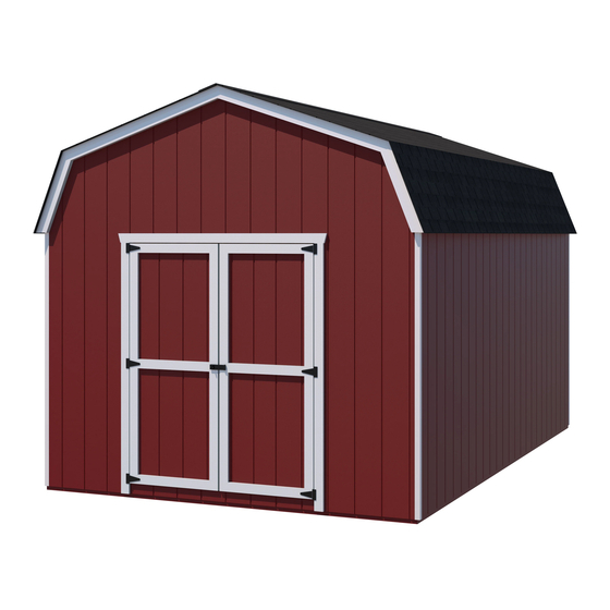
Page 3: Assembly Manual
16913 11/28/2022 ASSEMBLY MANUAL GAMBREL 8' x 12' Includes 8' x 12' Building and Floor Instructions KEEP THIS MANUAL FOR FUTURE REFERENCE Building 8' x 12' I M PO RTANT! READ INSTRUCTIONS THOROUGHLY PRIOR TO BEGINNING ASSEMBLY. BEFORE YOU BEGIN •... - Page 4 TOOLS Required Optional q Phillips q Tool Belt/ q Utility Knife Screwdriver Nail Pouch q Shingle Blades q Tin Snips q Drill / Driver (for drip edge) q Caulk Gun q 5/16" Drill Bit q Chalk Line q 1/8" Drill Bit q #2 Philips Drive Bit q Paint Tools q Nail Gun...
-
Page 5: Parts List
PARTS IDENTIFICATION AND SIZES WOOD SIZE CONVERSION CHART Treated lumber is stamped: stamped on some parts. Nominal Board Size Actual Size 2 x 4 ....1-1/2" x 3-1/2" (3,8 x 8,9 cm) 1 x 4 ....3/4" x 3-1/2" (1,9 x 8,9 cm) 2 x 3 ....1-1/2"... - Page 6 WALL PANELS & DOORS Wall panels are 3/8" (1,0 cm) thick. NOTE: Panel parts are not stamped. 3/8 x 42-1/2 x 48" 3/8 x 42-1/2 x 48" (1 x 108 x 121,9 cm) (1 x 108 x 121,9 cm) LEFT DOOR RIGHT DOOR 3/8 x 48 x 48"...
-
Page 7: Door Hardware
DOOR HARDWARE Spring-Bolt T & D Handle 8 x 16" (20,3 x 35,6 cm) 1" (2,5 cm) 1/2" (13 mm) 1-1/2" (3,8 cm) (4 screws in each package) (2 screws in each package) (8' Z-Channel) NAIL BOXES & NAIL BAGS BOXES 3"... -
Page 8: Optional Materials
ADDITIONAL MATERIALS FOUNDATION OR FLOOR MATERIALS • This shed kit includes a complete wood floor system. • This shed kit does not include ANY leveling materials. • See the FLOOR LEVELING section on page 7 for recommended methods and suggested materials to properly level your floor, as this will vary depending on your specific site. - Page 9 FLOOR LEVELING OPTIONS There are multiple ways to level your floor frame. Our recommended leveling method is shown below. Leveling materials are not included in this kit. PREFERRED METHOD - 4x4 TREATED RUNNERS • 3" Screw angled into 4x4. 4x4 Runners •...
- Page 10 CONCRETE FOUNDATION If you choose to install your kit on a concrete slab refer to the diagram below. Treated Sill Plate Caulk between sill plate and concrete. 3-1/2" (8,9 cm) 4" (10,2 cm) Building Size Actual Floor Size 8' x 12' (243,8 x 365,8 cm) 96"...
- Page 11 FLOOR FRAME PARTS REQUIRED: Look for 3" (7,6 cm) TREATED TREATED Stamp 2 x 4 x 48" (5,1 x 10,2 x 121,9 cm) TREATED 2 x 4 x 93" (5,1 x 10,2 x 236,2 cm) TREATED 2 x 4 x 96" (5,1 x 10,2 x 243,8 cm) BEGIN Arrange parts as shown on a flat surface.
- Page 12 FLOOR FRAME LEVEL AND SQUARE FLOOR FRAME Before attaching floor decking, it is important to level and square the floor frame. A level and square floor frame is required to correctly construct your shed. BEGIN See page 7 for the preferred floor leveling method. Use level and check the frame is level before applying floor panels.
- Page 13 FLOOR PANELS PARTS REQUIRED: x186 2" (5,1 cm) 5/8 x 48 x 96" 3/4" GAUGE (1,6 x 121,9 x 243,8 cm) BLOCK ¸ BEGIN Place right 48"x 96" panel on frame with rough side up (painted grid lines), flush at edges. Use GAA as a gauge block to maintain the 3/4"...
- Page 14 IMPORTANT! Ensure the floor frame is level after installing floor panels. Re-level if necessary. • The floor should be used as a stable work surface for wall construction. HINT: • Organize your assembly procedure during the build process to avoid over-handling of the walls. BACK WALL SIDE WALL SIDE WALL...
- Page 15 WALL PANEL INSTALLATION HINTS & EXAMPLES PARTS REQUIRED: 2" (5,1 cm) 3/4" GAUGE BLOCK 3/8 x 48 x 48" (1 x 121,9 x 121,9 cm) Ensure your wall is square by installing one panel and squaring frame. Install all wall panels with the primed side facing up. BEGIN 2 Nails Place (1) (48"...
- Page 16 BACK WALL PARTS REQUIRED: 3" (7,6 cm) 2 x 3 x 45-1/2" (5,1 x 7,6 x 115,6 cm) 3/16" (4,8 mm) Drill Bit 2 x 3 x 90-1/8"" (5,1 x 7,6 x 228,9 cm) BEGIN Arrange parts on the flat side, on a flat surface. Measure and mark. Secure parts with 3"...
- Page 17 BACK WALL PANELS PARTS REQUIRED: 1-1/2" (3,8 cm) 3/8 x 48 x 48" (1 x 121,9 x 121,9 cm) Install panels with the primed side facing up. Install (1) 48" x 48" wall panel on frame, as shown. Ensure 1-1/4" measurement on center brace. Maintain 1"...
- Page 18 BACK WALL PANELS PARTS REQUIRED: 1-1/2" (3,8 cm) 1-1/2" (3,8 cm) (8' Z-Channel) 3/8 x 48 x 48" (1 x 121,9 x 121,9 cm) Install 2nd 48" x 48" wall panel on frame, flush to installed panel. Maintain 1" along the top of the horizontal brace. Secure panel to horizontal brace with (4) 1-1/2"...
- Page 19 BACK WALL GABLE UNIT PARTS REQUIRED: 1-1/2" (3,8 cm) 2 x 3 x 35" (5,1 x 7,6 x 88,9 cm) Install gable panels with the primed side facing up. BEGIN Lay BSN on the flat side. Install left gable panel on BSN at measurements shown. Secure with 1-1/2"...
-
Page 20: Side Walls
SIDE WALLS PARTS REQUIRED: 3" (7,6 cm) 2 x 3 x 44" (5,1 x 7,6 x 111,8 cm) 2 x 3 x 48" (5,1 x 7,6 x 121,9 cm) 2 x 3 x 96" (5,1 x 7,6 x 243,8 cm) BEGIN Arrange parts on edge on floor as shown. - Page 21 SIDE WALL PANELS PARTS REQUIRED: x105 2" (5,1 cm) 3/4" GAUGE BLOCK 3/8 x 48 x48" (1,0 x 121,9 x 121,9 cm) Install panels with the primed side facing up. Arrange panels with the wood grain positioned vertically. Install (1) 48" x 72" panel flush to the top plate. Use the gauge block for consistent measurement on the wall stud.
-
Page 22: Front Wall
FRONT WALL PARTS REQUIRED: 3" (7,6 cm) 2 x 3 x 11-3/4" (5,1 x 7,6 x 29,8 cm) Temporary Support 2 x 3 x 51" (5,1 x 7,6 x 129,5 cm) Gusset 2 x 3 x 70-1/4" (5,1 x 7,6 x 178,4 cm) BEGIN HINT: Arrange parts EH and... - Page 23 FRONT WALL PARTS REQUIRED: 2" (5,1 cm) Temporary Support 69" Door Stiffener (175,3 cm) 1-1/2" (3,8 cm) 3" (7,6 cm) Install panels with the primed side facing up. 1-1/4" (3,2 cm) 1-1/2" (3,8 cm) Install (1) front wall panel Nails centered on frame and 1"...
- Page 24 RIGHT SIDE WALL INSTALLATION PARTS REQUIRED 3" (7,6 cm) Temporary Support 69" Door Stiffener (175,3 cm) 3" (7,6 cm) 2" (5,1 cm) BEGIN Center right wall on the floor. Ensure the 1" overlap is to the bottom. Install OO as a temporary brace. 1"...
-
Page 25: Back Wall Installation
BACK WALL INSTALLATION PARTS REQUIRED: 3" (7,6 cm) 1-1/2" (3,8 cm) 2" (5,1 cm) 2" (5,1 cm) 2" (3,8 cm) BEGIN Flush Flush Screw Center back wall on floor. Secure top and bottom Fig. A of wall with (1) 2" screw into top plate and (1) 2" screw into the floor frame (Fig. - Page 26 LEFT SIDE WALL INSTALLATION PARTS REQUIRED: 2" (5,1 cm) 3" (7,6 cm) 1-1/2" (3,8 cm) 2" (5,1 cm) BEGIN Center left wall on floor. Ensure the 1" overlap is to the bottom. Flush Secure top and bottom of wall with Fig.
- Page 27 FRONT WALL INSTALLATION PARTS REQUIRED: 2" (5,1 cm) 3" (7,6 cm) 2" (5,1 cm) 1-1/2" (3,8 cm) BEGIN Install front wall between left and right walls. 2" Secure wall with 2" screws into each side wall (5,1 cm) Screw top and bottom plates (Fig. A). ENSURE PANEL CORNERS ARE FLUSH.
- Page 28 RAFTERS PARTS REQUIRED: 3" (7,6 cm) 6 x 24" (15,2 x 61 cm) x144 2" (5,1 cm) 3/4" SUB-ASSEMBLED TRUSS GAUGE BLOCK You will build 7 rafters. (2) rafters will have ONE gusset. (5) rafters will have TWO gussets. BEGIN Make a jig so trusses will all have the same measurement using the shed floor and 3/4"...
- Page 29 RAFTERS PARTS REQUIRED: 3" (7,6 cm) TRUSS ASSEMBLY TRUSS ASSEMBLY WITH 1 GUSSET WITH 2 GUSSETS BEGIN Mark top plates to measurements shown. Place two-gusset rafters over studs and flush to the inside of front and back wall panels (Fig. A, Fig. B). Secure rafters with (2) 3"...
- Page 30 BACK GABLE UNIT and FRONT UPPER WALL PARTS REQUIRED: 1-1/2" (3,8 cm) 3" (7,6 cm) BEGIN Center back gable unit on top of Z-Channel. Hold gable unit secure with (1) 2" nail on each side. ENSURE GABLE IS CENTERED ON WALL BEFORE NAILING. Continue nailing lower edge of panels into top plate with 2"...
- Page 31 ROOF PANELS PARTS REQUIRED: 2" (5,1 cm) 3/4" GAUGE BLOCK 7/16 x 23-7/8 x 96" 7/16 x 23-7/8 x 48" (1,1 x 30,2 x 243,8 cm) (1,1 x 30,2 x 121,9 cm) Install roof panels with the rough side facing up (painted grid lines). Roof panels may cause serious injury until securely fastened.
- Page 32 ROOF PANELS PARTS REQUIRED: 2" (5,1 cm) 7/16 x 35-3/8 x 96" 3/4" GAUGE (1,1 x 89,9 x 243,8 cm) BLOCK Maintain spacing between the centers of the rafters by secureing panels with (1) 2" nail into each rafter. Secure with (2) nails at seam. 24-3/8"...
- Page 33 ROOF PANELS PARTS REQUIRED: 2" (5,1 cm) 7/16 x 35-3/8 x 48" (1,1 x 89,9 x 121,9 cm) Install 48" x 35-3/8" roof panel flush with the outer edge of front rafter (Fig. C) and flush to the installed panels. Secure panel with (2) 2"...
- Page 34 ROOF PANELS PARTS REQUIRED: 2" (5,1 cm) 3/4" GAUGE 7/16 x 11-7/8 x 96" 7/16 x 11-7/8 x 48" BLOCK (1,1 x 30,2 x 243,8 cm) (1,1 x 30,2 x 121,9 cm) Install (1) 11-7/8" x 96" roof panel flush with the outer edge of back rafter (Fig D) and flush to the top of installed panels.
- Page 35 ROOF PANELS PARTS REQUIRED: x144 2" (5,1 cm) Secure all roof panels with 2" nails spaced 6" apart on edges and 12" apart inside panel. 6" (15,2) cm) 12" (30,5) cm) Repeat steps to install roof panels on the opposite side. FINISH Your roof panels are now installed.
- Page 36 GABLE TRIM PARTS REQUIRED: 2" (5,1 cm) 2 x 4 x 35-3/4" (2,5 x 10,26 x 90,8 cm) 2 x 4 x 35-3/4" (2,5 x 10,26 x 90,8 cm) 2 x 4 x 36-3/4" (2,5 x 10,26 x 93,3 cm) 2 x 4 x 36-3/4"...
- Page 37 SIDE TRIM PARTS REQUIRED: 2" (5,1 cm) 3/8 x 1-3/4 x 45-3/8" (1,0 x 7,6 x 115,3 cm) 3/8 x 1-3/4 x 72-3/8" (1,0 x 7,6 x 183,8 cm) BEGIN Locate (2) 1-3/4" x 72-3/8" horizontal trim at the top of side wall. Push trim up flush to overhang of roof panels. Secure with 2"...
- Page 38 CORNER TRIM PARTS REQUIRED: 2" (5,1 cm) 3/8 x 1-3/4 x 45-3/8" (1,0 x 7,6 x 115,3 cm) BEGIN Install (2) 1-3/4" x 45-3/8" vertical battens on the front of shed. Battens are flush to the outside of side wall battens (Fig.
- Page 39 DOORS PARTS REQUIRED: 3" (7,6 cm) 1-1/4" (3,2 cm) 1-1/4 x 2-1/2 x 69" (3,2 x 7,6 x 175,3 cm) TEMPORARY SUPPORT 1 x 3 x 5" (2,5 x 7,6 x 12,7 cm) Left Door Right Door BEGIN Arrange parts as shown, on a flat surface. 3/8"...
- Page 40 DOORS PARTS REQUIRED: 3" (7,6 cm) Temporary Support 69" Door Stiffener (175,3 cm) Install temporary support OO flush under wall panels for doors to rest on, Secure with (2) 3" screws (Fig. A). Flush under panel Fig. A TEMPORARY SUPPORT Center doors in door opening.
- Page 41 DOOR PARTS REQUIRED: 2" (5,1 cm) 3/4" (1,9 cm) 19/32 x 2-1/2 x 55" (1,5 x 6,3 x 139,7 cm) BEGIN Reinforce the door trim with 3/4" screws through door panel into trim (Fig. A). Locate screws as shown in Fig. B. Use two screws at seams. Center trim ZB over doors and secure with 2"...
- Page 42 DOOR STIFFENERS PARTS REQUIRED: 2" (5 cm) 69" Door Stiffener (175,3 cm) BEGIN With left door closed, center a door stiffener OO vertically on the left door in the door opening (Fig. A). OO will offset the left door 1" OUT past the door trim 1" (Fig. B). Secure OO with (7) 2"...
- Page 43 DOOR HARDWARE PARTS REQUIRED: 1-1/2" (3,8 cm) 1/2" (13 mm) Drill Bit 1/4" (6 mm) Drill Bit BEGIN Measure and mark location of hole on outside of right door as shown (Fig. A). Pre-drill hole with 1/4" drill. Re-drill hole with 1/2" drill (Fig. A). Keep drilled hole square to trim to avoid breaking edge of 1-1/4 "...
- Page 44 SPRING BOLTS PARTS REQUIRED: 1" (2,5 cm) 5/16" (0,8 cm) Drill Bit BEGIN Place bolt onto OO in open position with bolt end 3/8" down from frame. Bolt is open when loop is contacting base (Fig A). Mark and pre-drill holes for screws. Install bolt with screws supplied and drill 5/16"...
- Page 45 VENTS • Follow directions provided by manufacturer and these instructions. 1/2" (13 mm) 16" x 8" BEGIN Choose locations for (2) vents on opposite side walls,(1) at top and (1) at bottom. Cut out marked openings. Caulk behind vent flanges. Secure with 1/2"...
- Page 46 PAINT & CAULK - NOT INCLUDED - • Use acrylic latex caulk that is paintable. Caulk at all horizontal and vertical seams, between the trim and walls, and all around the door trim. • Use a high quality exterior acrylic latex paint. When painting your building, there are a few key areas that can be easily overlooked that must be painted: •...
- Page 47 SHINGLES - NOT INCLUDED - • Follow directions provided by manufacturer and these instructions. Familiarize yourself with a 3-Tab Shingle. Notch Notch SHINGLE NAIL PATTERN 1/2 " 1" Sealing Str 1" (1,3 cm) (2,5 cm) (2,5 cm) Half A Rain Slot Full Rain Slot NAILS NEVER DRIVE FASTENERS INTO OR ABOVE SEALING STRIPS.
- Page 48 SHINGLES continued... Install second row of shingles flush at top of first row's rain slots. Ensure 1" overhang or flush to drip edge at front, stagger each row. FRONT OF BACK OF SHED SHED Bend in roof 1" (2,5 cm) Notch Flush with rain slots.
- Page 49 SHINGLES continued... After shingles are installed over bend, nail down overlap using two roofing nails per tab. (2) Nails per tab. Continue installing rows of shingles to the peak. At the peak make sure there is a maximum of 5" or less to the rain slot, as shown below.
- Page 50 SHINGLES - RIDGE CAP • You will finishing off the top of the roof with a ridge cap made from shingles. BEGIN Cut shingles into THREE pieces. Hint: Use cut-off pieces first. 2" 2" (5,1 cm) (5,1 cm) 2" 2" 2"...
- Page 51 SHINGLES - RIDGE CAP continued... Continue installing ridge cap to back of roof. Make sure there is 4" between the shingle-color and edge of shingles. Trim cap off flush to shingles When you have 4" minimum of shingle color cut one piece to cap your roof. Install flush to shingles.
- Page 52 2 X 4 X 36-3/4" 24*/24* LEFT UT36122424200 Door Stiffener LSL 1-1/4 X 2-1/4 X 69 PET 12715 Truss Assembly TRUSS Sub-Assy Gambrel 8' Wide 30040 Black T&D Handle HANDLE - T 4" SHAFT & "D" 15375 PURCHASED COMPONENTS 6D Nails NAIL 6D 2"...
- Page 53 LIMITED CONDITIONAL WARRANTY* Backyard Storage Solutions, LLC warrants the following: Every product is warranted from defects in workmanship and manufacturing for 1 year. All accessories, hardware and metal components are warranted for 2 years. All Oriented Strand Board (OSB) is warranted for 2 years Siding and Trim is warranted for 10 years.
Need help?
Do you have a question about the GAMBREL and is the answer not in the manual?
Questions and answers