Table of Contents
Advertisement
Quick Links
16985
STOP!
STOP!
Call Us First!
DO NOT RETURN TO STORE.
For immediate help with assembly or product information
call our toll free number:
1-800-577-9663
or email:
customerservice@backyardproductsllc.com
Our staff is ready to provide assistance
April through October M-F 8:00 AM to 4:30 PM EST
Saturday 8:30 AM to 4:30 PM EST
November through March M - F 8:00 AM to 5:00 PM EST
Advertisement
Table of Contents

Related Manuals for Backyard Products HEARTLAND 16985


Summary of Contents for Backyard Products HEARTLAND 16985
- Page 1 16985 STOP! STOP! Call Us First! DO NOT RETURN TO STORE. For immediate help with assembly or product information call our toll free number: 1-800-577-9663 or email: customerservice@backyardproductsllc.com Our staff is ready to provide assistance April through October M-F 8:00 AM to 4:30 PM EST Saturday 8:30 AM to 4:30 PM EST November through March M - F 8:00 AM to 5:00 PM EST...
- Page 2 (This page intentionally left blank.)
-
Page 3: Assembly Manual
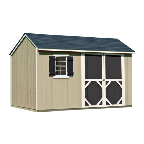
16985 04/16/2019 ASSEMBLY MANUAL A Backyard Products Company VALUE SERIES STOCKDALE 12' x 8' (366 x 244 cm) ACTUAL FLOOR SIZE IS 141 x 96" (358 x 244 cm) KEEP THIS MANUAL FOR FUTURE REFERENCE IM PORTAN T ! READ INSTRUCTIONS THOROUGHLY PRIOR TO BEGINNING ASSEMBLY. - Page 4 TOOLS Required Optional Tool Belt/ Utility Knife Phillips Nail Pouch Screwdriver Shingle Blades Caulk Gun Drill / Driver Tin Snips 3/8" Drill Bit (for drip edge) #2 Philips Drive Bit Paint Tools ...
-
Page 5: Additional Materials
ADDITIONAL MATERIALS FOUNDATION OR FLOOR MATERIALS • This shed kit includes a complete wood floor system. • This shed kit does not include ANY leveling materials. • See the FLOOR LEVELING section on page 8 for recommended methods and suggested materials to properly level your floor, as this will vary depending on your specific site. REINFORCED WOOD FLOOR FRAME (OPTIONAL) IMPORTANT! The included floor has been designed for general use. Depending on your specific use you may want to construct a heavy duty floor frame by adding additional floor joists (shown below as shaded). -
Page 6: Parts List
PARTS IDENTIFICATION AND SIZES Part identification WOOD SIZE CONVERSION CHART letters are stamped on some parts. All treated lumber Nominal Board Size Actual Size is stamped: 2 x 4 ....1-1/2" x 3-1/2" (3,8 x 8,9 cm) 1 x 4 ....3/4" x 3-1/2" (1,9 x 8,9 cm) 2 x 3 ....1-1/2"... - Page 7 WALL PANELS / DOOR PARTS LIST 3/8 x 48 x 72" 3/8 x 15-7/8 x 72" (1 x 122 x 183 cm) (1 x 40 x 183 cm) 1-1/2 x 2-1/2 x 69" (3,8 x 6,3 x 175,3 cm) 3/8 x 7-7/8 x 94-1/2" 3/8 x 7-7/8 x 46-1/2"...
- Page 8 SHELF & WINDOW PARTS LIST 1 x 3 x 96" 23-7/8 x 96" (2,5 x 7,6 x 244 cm) (61 x 244 cm) Peg Board Window 7/16 x 20 x 96" 7/16 x 11-3/4 x 96" (1,1 x 51 x 244 cm) (1,1 x 30 x 244 cm) NAIL BOXES (Shown actual size) x3 Boxes...
- Page 9 BUILDING ANATOMY This building has been designed using our patented EZ Frame construction method. EZ Frame is a unique construction method which has been engineered to use fewer framing members. This reduces assembly time and cost by as much as 30% compared to conventional construction methods.
- Page 10 FLOOR LEVELING OPTIONS There are multiple ways to level your floor frame. Our recommended leveling method is shown below. Leveling materials are not included in this kit. PREFERRED METHOD - 4x4 TREATED RUNNERS • 3" Screws angled into 4x4. • (2) at each point frame •...
- Page 11 CONCRETE FOUNDATION If you choose to install your kit on a concrete slab refer to the diagram below. Treated Sill Plate Caulk between sill plate and concrete. 3-1/2" (8,9 cm) 4" (10 cm) Building Size Actual Size 12'x 8' (366 x 244 cm) 141"...
-
Page 12: Parts Required
FLOOR FRAME PARTS REQUIRED: 3" (7,6 cm) 2 x 4 x 48" (5,1 x 10,2 x 121,9 cm) 2 x 4 x 93" (5,1 x 10,2 x 236,2 cm) BEGIN Orient parts as shown on fl at surface. Measure and mark. HINT: Secure using (2) 3"... - Page 13 LEVEL AND SQUARE FLOOR FRAME Before installing fl oor decking it is important to level and square the fl oor frame. A level and square fl oor frame is required to correctly construct your shed. BEGIN See page 7 for the preferred fl oor leveling method. Use a level and check that the frame is level before installing fl oor panels.
- Page 14 FLOOR PANELS PARTS REQUIRED: 2" (5,1 cm) 3/4" GAUGE BLOCK 5/8 x 48 x 96" (1,6 x 121,9 x 243,8 cm) Ensure your floor frame is square by installing (1) panel and squaring frame. BEGIN Install a 48" x 96" panel with the rough side up (painted-grid lines side) and with the 48" edge and corner flush to the floor frame (Fig A).
- Page 15 FLOOR PANELS PARTS REQUIRED: x110 2" (5,1 cm) 3/4" GAUGE BLOCK 5/8 x 48 x 96" 5/8 x 45 x 96" (1,6 x 121,9 x 243,8 cm) (1,6 x 114,3 x 243,8 cm) Continue installing panels with rough side up (painted grid lines). Install 44-5/8"...
- Page 16 IMPORTANT! Check the floor frame is level after installing floor panels. Re-level if needed. • The floor should be used as a stable work surface for wall construction. • Organize your assembly procedure during the build process HINT: to avoid over-handling of the walls. BACK WALL GABLE WALL GABLE WALL FRONT WALL...
- Page 17 LEFT WALL PARTS REQUIRED: 1-1/4" (3,2 cm) 2 x 3 x 76-1/4" (5 x 7,6 x 194 cm) BEGIN Orient parts on the flat on floor as shown (Fig. A,B). Panel should be primed side down (Fig. B). Edges of panel should be flush to MM. Secure using 1-1/4"...
- Page 18 LEFT WALL PARTS REQUIRED: 1-1/4" (3,2 cm) 2 x 3 x 70-1/2" (5 x 7,6 x 179 cm) Orient parts on the fl at on fl oor as shown (Fig. A, B). Panel should be primed side down (Fig. B). Edges of panel should be fl ush to NO.
- Page 19 LEFT WALL PARTS REQUIRED: 1-1/2" (3,8 cm) LEFT WALL REAR ASSEMBLY 2 x 3 x 13" (5 x 7,6 x 33 cm) 2 x 3 x 32-1/2" (5 x 10 x 83 cm) 2 x 3 x 96" (5 x 7,6 x 244 cm) BEGIN Orient KZ and PT on flat on floor as shown.
- Page 20 LEFT WALL PARTS REQUIRED: 1-1/2" (3,8 cm) 2 x 3 x 21-1/2" (5 x 7,6 x 55) 2 x 3 x 29-1/2" (5 x 10 x 75 cm) 2 x 3 x 96" (5 x 7,6 x 244 cm) 3/4" GAUGE TEMPORARY SPACER BLOCK 5/8 x 3 x 14"...
- Page 21 LEFT WALL PARTS REQUIRED: 1-1/2" (3,8 cm) LEFT WALL FRONT ASSEMBLY 2 x 3 x 13" (5 x 7,6 x 33 cm) Place panel onto frame primed side up. Do not nail Secure panel using 1-1/2" nails 6" (15 cm) apart on in groove.
- Page 22 RIGHT WALL PARTS REQUIRED: 1-1/4" (3,2 cm) 2 x 3 x 76-1/4" (5 x 7,6 x 194 cm) BEGIN Orient parts on the flat on floor as shown (Fig. A,B). Panel should be primed side down (Fig. B). Edges of panel should be flush to MM. Secure panel using 1-1/4"...
- Page 23 RIGHT WALL PARTS REQUIRED: 1-1/4" (3,2 cm) 2 x 3 x 70-1/2" (5 x 7,6 x 179 cm) Orient parts on the fl at on fl oor as shown (Fig. A, Fig.B). Panel should be primed side down (Fig. B). Edges of panel should be fl ush to NO.
- Page 24 RIGHT WALL PARTS REQUIRED: 1-1/2" (3,8 cm) RIGHT WALL REAR ASSEMBLY 2 x 3 x 13" (5 x 7,6 x 33 cm) 2 x 3 x 32-1/2" (5 x 10 x 83 cm) 2 x 3 x 96" (5 x 7,6 x 244 cm) BEGIN Orient KZ and PT on the flat on floor as shown.
- Page 25 RIGHT WALL PARTS REQUIRED: 1-1/2" (3,8 cm) 2 x 3 x 32-1/2" (5 x 10 x 83 cm) 2 x 3 x 21-1/2" (5 x 7,6 x 55) TEMPORARY SPACER 5/8 x 3 x 14" (1,6 x 7,6 x 35,5 cm) Place KZ flush on PT and secure using 1-1/2"...
- Page 26 RIGHT WALL PARTS REQUIRED: 1-1/2" (3,8 cm) RIGHT WALL FRONT ASSEMBLY 2 x 3 x 13" (5 x 7,6 x 33 cm) Place panel onto frame primed side up. Do not nail Nail using 1-1/2" (3,8 cm) nails 6" (15 cm) apart in groove.
- Page 27 BACK WALL PARTS REQUIRED: 3" (7,6 cm) 2 x 3 x 66-1/2" (5 x 7,6 x 169 cm) 2 x 3 x 46-1/2" (5 x 7,6 x 118 cm) 2 x 3 x 94-1/2" (5 x 7,6 x 240 cm) BEGIN Orient parts on edge on floor as shown.
- Page 28 BACK WALL PARTS REQUIRED: 2" (5 cm) 3/8 x 48 x 72" (1 x 122 x 183 cm) 3/4" GAUGE BLOCK 2 x 3 x 13" (5 x 7,6 x 33 cm) as spacer Ensure your wall frame is square by installing one panel and squaring frame.
- Page 29 BACK WALL PARTS REQUIRED: x192 2" (5 cm) 2 x 3 x 13" (5 x 7,6 x 33 cm) as spacer 3/8 x 48 x 72" (1 x 122 x 183 cm) 3/4" GAUGE BLOCK Place center 48" panel on frame as shown with primed side facing up.
-
Page 30: Front Wall
FRONT WALL PARTS REQUIRED: 3" (7,6 cm) 2 x 3 x 14-1/2" (5 x 7,6 x 36,8 cm) 2 x 3 x 62-1/2" (5 x 7,6 x 158,8 cm) 2 x 3 x 46-1/2" (5 x 7,6 x 118 cm) 2 x 3 x 68"... - Page 31 FRONT OVERHANG PANELS PARTS REQUIRED: 1-1/4" (3,2 cm) 2 x 3 x 7-7/8" (5 x 7,6 x 20 cm) 3/8 x 7-7/8 x 94-1/2" (0,9 x 20 x 240 cm) 3/8 x 7-7/8 x 46-1/2" (0,9 x 20 x 118 cm) BEGIN Orient two overhang panels with the primed side up.
- Page 32 FRONT OVERHANG PANELS PARTS REQUIRED: 1-1/4" (3,2 cm) Overhang Overhang Place overhang on wall panel, fl ush to back side and ends. Place overhang fl ush to 2 x 3" (Fig. A.) Screw into top plate using (14) 1-1/4"(3,2 cm) screws. Keep overhang fl ush to 2 x 3"...
- Page 33 FRONT WALL PARTS REQUIRED: 2" (5 cm) 3/4" GAUGE BLOCK Ensure your wall frame is square by installing one panel and squaring frame. Do not nail BEGIN in groove. Place the panel onto wall frame flush under overhang with primed side up as shown (Fig.
- Page 34 FRONT WALL PARTS REQUIRED: 2" (5 cm) 3" (7,6 cm) 3/8 x 15-7/8 x 72" (1 x 40 x 183 cm) 2 x 3 x 96" (5 x 7,6 x 244 cm) Continue installing panels primed side up fl ush under overhang (Fig.
- Page 35 LEFT WALL INSTALLATION PARTS REQUIRED: 3" (7,6 cm) 3" (7,6 cm) 2" (5 cm) 2 x 3 x 96" (5 x 7,6 x 244 cm) BEGIN Center left wall assembly on the 96" fl oor dimension. Use PT as a temporary brace. Secure using (2) 3"...
-
Page 36: Back Wall Installation
BACK WALL INSTALLATION PARTS REQUIRED: 2" (5 cm) 3" (7,6 cm) 3" (7,6 cm) Install back wall with the 1-1/2" panel overhang at the top. ¸ BEGIN Center back wall on fl oor. Secure the lower wall corner to the side wall trim using (1) 2" nail (Fig. A). 1-1/2" (3,8 cm) Trim 2"... - Page 37 RIGHT WALL INSTALLATION PARTS REQUIRED: 2" (5 cm) 3" (7,6 cm) 3" (7,6 cm) BEGIN Center right wall on fl oor, side-to-side. Secure the lower back wall corner to the right wall trim using (1) 2" nail (Fig. A). 2" (5 cm) Trim Nail Fig.
- Page 38 FRONT WALL INSTALLATION PARTS REQUIRED: 3" (7,6 cm) 3" (7,6 cm) 2" (5 cm) x26 BEGIN Center front wall on floor side-to-side. Check the 64" door opening is held before nailing. 64" 2" (5 cm) (162,6 cm) Nail Nail the front wall flush to the floor using 2"...
- Page 39 FRONT WALL PARTS REQUIRED: 3" (7,6 cm) 2 x 3 x 22-1/2" (5 x 7,6 x 57 cm) Working inside of front wall, install LV flush to window opening using 3" nails as shown. Flush to 1-1/2" opening (3,8 cm) 3"...
- Page 40 FRONT WALL PARTS REQUIRED: 3" (7,6 cm) 2 x 3 x 68" (5 x 7,6 x 173 cm) 2 x 3 x 13" (5 x 7,6 x 33 cm) Remove temporary support in door opening. Assemble RK to OT using (1) 3" screw (Fig. A). FINISH Use OT and RK as a temporary brace to support top plate.
- Page 41 RAFTER JIG PARTS REQUIRED: 3" (7,6 cm) 2 x 3 x 13" (5 x 7,6 x 33 cm) 3/8 x 5-3/8 x 5-1/2" (1 x 13,6 x 14 cm) BEGIN Make a rafter jig to make sure all rafters are assembled the same. Measure from corner of back wall and RK (already installed) as shown.
- Page 42 RAFTERS PARTS REQUIRED: x120 2" (5 cm) 8 x 24" (20 x 61 cm) Gusset 2 x 4 x 65-5/8" (5 x 10 x 167 cm) Rafter 2 x 4 x 46-13/16" (5 x 10 x 119 cm) Rafter BEGIN You will assemble (5) rafters.
-
Page 43: Left Side
TRIM CAPS PARTS REQUIRED: 1-1/4" (3,2 cm) 2-5/8 x 5-3/8 x 5-1/2" (6,6 x 13,6 x 14 cm) 1 Left / 1 Right BEGIN Install trim caps with primed side out and fl ush with soffi t. Secure using (2) 1-1/4" screws on both sides. Install with primed side facing out. - Page 44 GABLE TRIM PARTS REQUIRED: 1-1/4" (3,2 cm) 2 x 3 x 65" (5 x 7,6 x 165 cm) BEGIN Install the back trim first, flush to back panel, trim, and panel edge as shown. Secure using (8) 1-1/4" screws 9" apart from inside shed. 9"...
- Page 45 GABLE TRIM PARTS REQUIRED: 1-1/4" (3,2 cm) 2 x 3 x 46-7/8" (5 x 7 x 119 cm) Install the front trim, fl ush to peak and panel edge as shown. Secure using (6) 1-1/4" screws from inside shed. Repeat Steps for opposite Side Wall. Flush to Flush panel...
- Page 46 RAFTERS PARTS REQUIRED: 3" (7,6 cm) 2" (5 cm) BEGIN Mark top of wall frames to measurement shown. Locate Rafter centered on marks. Hold rafter end fl ush to back wall and overhang. Secure from under overhang using (2) 2" screws (Fig. A). Secure opposite end through panel into rafter end using (1) 2"...
- Page 47 TRIM PARTS REQUIRED: 2" (5 cm) 3/4 x 2-1/2 x 72-3/8" (1,9 x 6,3 x 184 cm) BEGIN Orient parts as shown and attach to ends of rafters, using (2) 2" fi nish nails (Fig. A). Trim is fl ush at ends to sidewall trim. 72-3/8"...
- Page 48 DOOR SUPPORT PARTS REQUIRED: 2" (5 cm) 5/8 x 3-7/8 x 96" (1,6 x 9,8 x 244 cm) BEGIN Position support fl ush with bottom edge of top plate and side wall panel and attach with 2" (5 cm) nails as shown. Remove temporary brace after support is installed.
- Page 49 WORKBENCH PARTS REQUIRED: 2" (5 cm) 7/16 x 20 x 96" (1,1 x 51 x 244 cm) 2 x 3 x 96" (5 x 7,6 x 244 cm) BEGIN Position bench top to PT fl ush at ends and maintaining 1/4" overhang (Fig. A). Secure using 2"...
- Page 50 SHELVES PARTS REQUIRED: 2" (5 cm) 7/16 x 11-3/4 x 96" (1,1 x 30 x 244 cm) 2 x 3 x 96" (5 x 7,6 x 244 cm) You will build two shelves. BEGIN Position shelf to PT fl ush at ends and maintaining 1/4" overhang as shown (Fig. A). Secure using 2"...
- Page 51 PEGBOARD PARTS REQUIRED: 3/4" (19 mm) 23-7/8 x 96" (61 x 244 cm) Peg Board 1 x 3 x 96" (2,5 x 7,6 x 244 cm) BEGIN Position pegboard to 1 x 3" fl ush at ends and edge, as shown (Fig. A). Rough side up Secure using 3/4"...
- Page 52 WORKBENCH PARTS REQUIRED: 20" 3" (7,6 cm) (51 cm) 2" (5 cm) 2 x 3 x 24-1/16" (5 x 7,6 x 61 cm) BEGIN Place workbench into gap in side wall upright. Secure using 2" nails as shown. Level and attach KK to upright and workbench using (4) 3"...
- Page 53 PEGBOARD PARTS REQUIRED: 3" (7,6 cm) 2" (5 cm) 2 x 3 x 13" (5 x 7,6 x 33 cm) 1" (25 mm) BEGIN Install RK at back corner of workbench into outside trim using 3" screws as shown. Place pegboard onto workbench with 1 x 3 Trim to bottom, facing out. Secure pegboard at top using (13) 1"...
- Page 54 SHELVES PARTS REQUIRED: 2" (5 cm) 11-3/4" (30 cm) BEGIN Place shelf into gap in side wall upright. Secure using 2" nails as shown. You will screw the ends of workbench and shelf from outside of shed. Shelf 10-1/2" 11-3/4" Approximately (30 cm) Window...
- Page 55 SHELVES PARTS REQUIRED: 3" (7,6 cm) Measure and mark outside nail locations for workbench and shelf on back wall as shown. Assistance may be required to hold shelf and workbench level. FINISH Nail through marks on wall panel into ends of workbench and shelf supports. Repeat procedure at opposite ends of shelf and workbench.
- Page 56 SHELVES PARTS REQUIRED: 1-1/4" (3,2 cm) 11-3/4" (30 cm) 3" (7,6 cm) 3" (7,6 cm) 2 x 3 x 13" (5 x 7,6 x 33 cm) BEGIN Install RK fl ush against top plate and outer wall panel. Secure using 3" screws as shown (Fig. A). Place shelf into gap in side wall upright.
- Page 57 ROOF PANELS PARTS REQUIRED: 2" (5 cm) 3/4" GAUGE 7/16 x 48 x 96" BLOCK (1,1 x 122 x 244 cm) Roof panels may cause serious injury until securely fastened. BEGIN You must square the roof by attaching one panel fist. You will use the panels’ long edge as a lever to bring your roof into square.
- Page 58 ROOF PANELS PARTS REQUIRED: x108 2" (5 cm) 3/4" GAUGE BLOCK 7/16 x 47-7/8 x 48" 7/16 x 48 x 96" (1,1 x 122 x 122 cm) (1,1 x 122 x 244 cm) Keep spacing between the center of the rafters at the lower edge of the panel and secure using (1) 2"...
- Page 59 ROOF PANELS PARTS REQUIRED: 2" (5 cm) 7/16 x 18 x 96” (1,1 x 46 x 244 cm) 3/4" GAUGE BLOCK 7/16 x 18 x 48" (1,1 x 46 x 122 cm) Install 18 x 96" panel as shown fl ush to panels and 3/4" on rafter (Fig. A) and with 3/8"...
- Page 60 DOORS PARTS REQUIRED: 3" (5 cm) x8 1-1/4 x 2-1/2 x 69" (3,2 x 6,3 x 175,3 cm) 2 x 3 x 68" (5 x 7,6 x 173 cm) HINT: Look for 3/8" SPACER attached to doors. Left Door Right Door BEGIN 3/8" offset is to top. Look for red Orient parts as shown on flat surface.
- Page 61 DOORS PARTS REQUIRED: 3" (7,6 cm) 1-1/4 x 2-1/2 x 69" (3,2 x 6,3 x 175,3 cm) Attach temporary support OO as a ledger board for doors to rest on, using three 3" screws. Measure 72" down from underside of overhang (Fig. A). Locate center of door opening and mark.
- Page 62 DOORS PARTS REQUIRED: 3/4" (1,9 cm) Bagged separately/ 64" Metal Threshold special coating BEGIN Reinforce the door trim using 3/4" screws through door panel into trim (Fig. A). Locate screws as shown (Fig. B). Use two screws at seams. Remove 3/8" spacers from doors. Door Panel Center metal threshold between doors and secure...
- Page 63 DOORS PARTS REQUIRED: 2" (5 cm) 1-1/2 x 2-1/2 x 69" (3,8 x 6,3 x 175,3 cm) BEGIN With left door closed, center a weatherstrip OO vertically on the left door in the door opening (Fig. A). OO will offset the left door 1" OUT past the door trim 1"...
-
Page 64: Door Hardware
DOOR HARDWARE PARTS REQUIRED: 3/8" (9 mm) Drill Bit 3/4" (1,9 cm) x8 3/4" (1,9 cm) x7 BEGIN Mount one barrel bolt fl ush at top of OO on left door using 3/4" screws as shown (Fig A). Mount the second barrel bolt fl ush at bottom of OO on left door using 3/4" screws as shown (Fig B). - Page 65 COLLAR TIE PARTS REQUIRED: 3" (7,6 cm) 2 x 3 x 68" (5 x 7,6 x 173 cm) BEGIN Position and level OT on rafter that is centered over door opening. Install OT using 3" nails as shown. Level Flush Flush Rafter centered over door opening.
- Page 66 SHUTTERS PARTS REQUIRED: 1" (25 mm) 5/8 x 3 x 25" (1,6 x 7,6 x 63,5 cm) 5/8 x 3 x 8" (1,6 x 7,6 x 20 cm) You will build two shutters the same. BEGIN Position parts primed side-down on fl oor as shown. You will build two shutters the same.
- Page 67 WINDOW PARTS REQUIRED: 1-1/4" (3,2 cm) Window 23-3/4" x 16-1/2" (63 x 42 cm) BEGIN Seal window using high-quality exterior-grade caulk. Install window using (4) 1-1/4" screws as shown. Mark center of window frame as shown. HINT: Caulk behind frame near edge before installing.
- Page 68 SHUTTERS / WINDOW TRIM PARTS REQUIRED: 2" (5 cm) 3/4" (19 mm) 5/8 x 3 x 21-3/4" (1,6 x 7,6 x 55 cm) BEGIN Locate one shutter centered on marks as shown. First, attach shutter using a 2" fi nish nail at "dot". Nail into wall frame inside.
- Page 69 DOOR TRIM PARTS REQUIRED: 3/4" (19 mm) 5/8 x 4 x 14" (1,6 x 10 x 35,5 cm) BEGIN Install parts WNA on lower section of door panels as shown. Secure each using (2) 3/4" screws. FINISH Your door trim is now installed...
- Page 70 PAINT & CAULK - NOT INCLUDED - • Use acrylic latex caulk that is paintable. Caulk at all horizontal and vertical seams, between the trim and walls, and all around the door trim. • Use a high quality exterior acrylic latex paint. When painting your building, there are a few key areas that can be easily overlooked that must be painted: •...
- Page 71 SHINGLES - NOT INCLUDED - • Follow directions provided by manufacturer and these instructions. Familiarize yourself with a 3-Tab Shingle. Notch Notch SHINGLE NAIL PATTERN 1/2" 1" Sealing Strip 1" (1,3 cm) (2,5 cm) (2,5 cm) Half A Rain Slot Full Rain Slot NAILS NEVER DRIVE FASTENERS INTO OR ABOVE SEALING STRIPS. BEGIN Install first starter row upside down and color up with a 1" overhang at back and bottom of roof panel. Use (4) nails per shingle. Starter row must be straight and level all the way across with lower edge of roof deck.
- Page 72 SHINGLES continued... Beginning at front of shed, install first row of shingles with notch at 1" past roof edge or flush with drip edge. Roof Deck FRONT OF BACK OF SHED SHED 1" (2,5 cm) Flush with starter row. Notch - or - Drip Edge Flush with starter row.
- Page 73 SHINGLES continued... Continue installing rows of shingles to the peak. At the peak make sure there is a maximum of 5" or less to the rain slot, as shown below. If shingles overlap at ridge cut to peak with a utility knife. 5"...
- Page 74 SHINGLES - RIDGE CAP • You will finish off the top of the roof with a ridge cap made from shingles. BEGIN Cut shingles into THREE pieces. Hint: Use cut-off pieces first. 2" 2" (5 cm) (5 cm 2" 2" 2"...
- Page 75 SHINGLES - RIDGE CAP continued... Continue installing ridge cap to back of roof. Make sure there is 4" between the shingle-color and edge of shingles. 4" (10 cm) Trim cap off fl ush to shingles When you have 4" minimum of shingle color cut one piece to cap your roof. Cut at top of rain slot.
-
Page 76: Claim Procedure
LIMITED CONDITIONAL WARRANTY* Backyard Storage Solutions, LLC warrants the following: Every product is warranted from defects in workmanship and manufacturing for 1 year. All accessories, hardware and metal components are warranted for 2 years. All Oriented Strand Board (OSB) is warranted for 2 years Siding and Trim is warranted for 10 years.