Advertisement
Quick Links
DO NOT RETURN TO STORE.
For immediate help with assembly or product information
customerservice@backyardproductsllc.com
customerservice@backyardproductsllc.com
Our staff is ready to provide assistance
April through October M-F 8:00 AM to 6:00 PM EST
Saturday 8:30 AM to 4:30 PM EST
November through March M - F 8:00 AM to 5:00 PM EST
STOP!
STOP!
Call Us First!
call our toll free number:
1-800-577-9663
1-800-577-9663
or email:
16778
Advertisement

Related Manuals for Backyard Products Heartland CLASSIC GENTRY GABLE 12' x 12'


Summary of Contents for Backyard Products Heartland CLASSIC GENTRY GABLE 12' x 12'
- Page 1 16778 STOP! STOP! Call Us First! DO NOT RETURN TO STORE. For immediate help with assembly or product information call our toll free number: 1-800-577-9663 1-800-577-9663 or email: customerservice@backyardproductsllc.com customerservice@backyardproductsllc.com Our staff is ready to provide assistance April through October M-F 8:00 AM to 6:00 PM EST Saturday 8:30 AM to 4:30 PM EST November through March M - F 8:00 AM to 5:00 PM EST...
- Page 2 (This page intentionally left blank.)
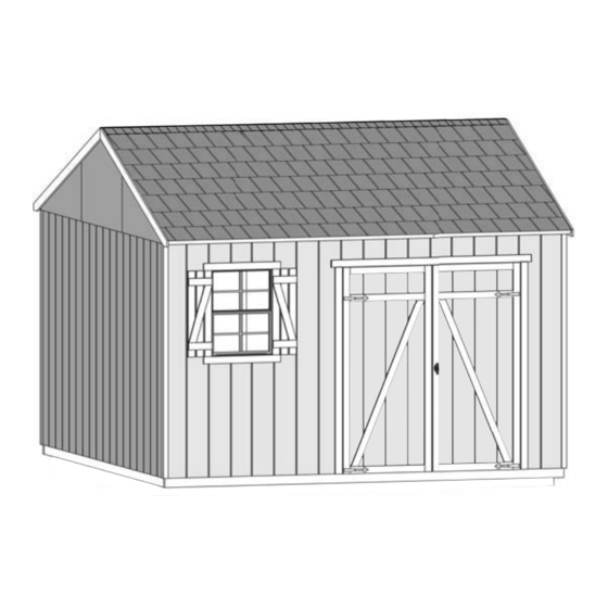
- Page 3 16778 01/18/12 ASSEMBLY MANUAL A Backyard Products Company CLASSIC GENTRY GABLE 12' x 12' (365,8 x 365,8 cm) BUILDING SIZE ACTUAL FLOOR SIZE 12' x 12' (365,8 x 365,8 cm) 12' x 12' (365,8 x 365,8 cm) KEEP THIS MANUAL FOR FUTURE REFERENCE IMPORTA N T! READ INSTRUCTIONS THOROUGHLY PRIOR TO BEGINNING ASSEMBLY.
- Page 4 TOOLS Required Optional ❑ Phillips ❑ Tool Belt/ ❑ Utility Knife Screwdriver Nail Pouch ❑ Shingle Blades ❑ Drill / Driver ❑ Tin Snips ❑ 3/8" Drill Bit ❑ Caulk Gun (for drip edge) ❑ #2 Philips Drive Bit ❑ Chalk Line ❑...
- Page 5 ADDITIONAL MATERIALS COMPLETING YOUR SHED You will need these additional materials: 3-TAB SHINGLES (Bundles)....PAINT FOR TRIM ......1 Quart Use 100% acrylic latex exterior paint. PAINT FOR SIDING (Gallons)....WOOD GLUE ....Exterior Rated Use 100% acrylic latex exterior paint. (2) coats recommended.
- Page 6 PARTS IDENTIFICATION AND SIZES Double letter part identiÚ cation WOOD SIZE CONVERSION CHART is stamped on some parts. Nominal Board Size Actual Size 2" x 4"....1-1/2" x 3-1/2" (3,8 x 8,9 cm) 1" x 4"....3/4" x 3-1/2" (1,9 x 8,9 cm) 2"...
- Page 7 PARTS IDENTIFICATION AND SIZES 2 x 4 x 96" (5,1 x 10,2 x 243,8 cm) 1 x 4 x 96" (2,5 x 10,2 x 243,8 cm) 1 x 3 x 96" (2,5 x 7,6 x 243,8 cm) 2 x 3 x 96" (5,1 x 7,6 x 243,8 cm) 2 x 4 x 48"...
- Page 8 WALL PANELS 3/8 x 48 x 84" (1 x 121,9 x 213,4 cm) 3/8 x 48 x 84" 3/8 x 48 x 84" 3/8 x 48 x 84" (1 x 121,9 x 213,4 cm) (1 x 121,9 x 213,4 cm) LEFT DOOR RIGHT DOOR (1 x 121,9 x 213,4 cm)
- Page 9 CONCRETE FOUNDATION If you choose to install your kit on a concrete slab refer to the diagram below. Attach the sill plates on the foundatIon as shown, and continue on to page 11. Treated Sill Plate Caulk between sill plate and concrete.
- Page 10 FLOOR LEVELING OPTIONS There are multiple ways to level your Û oor frame. Our recommended leveling method is shown below. Leveling materials are not included in this kit. FOUNDATION OR FLOOR MATERIALS • This shed does not include any Û oor or leveling materials. •...
- Page 11 FLOOR FRAME LEVEL AND SQUARE FLOOR FRAME Before attaching Û oor decking, it is important to level and square the Û oor frame. A level and square Û oor frame is required to correctly construct your shed. BEGIN See page 8 for the preferred Û oor leveling method. Use level and check the frame is level before applying Û...
- Page 12 IMPORTANT! I M P O R T A N T ! Check the Û oor frame is level after installing Û oor panels. Re-level if needed. • The Û oor should be used as a level work surface for wall construction. •...
- Page 13 SIDE WALL FRAME PARTS REQUIRED: 3" (7,6 cm) 2 x 4 x 48" (5,1 x 10,2 x 121,9 cm) 2 x 4 x 78-1/2" (5,1 x 10,2 x 199,4 cm) 2 x 4 x 96" (5,1 x 10,2 x 243,8 cm) IMPORTANT! You will build two walls the same.
- Page 14 SIDE WALL PANELS PARTS REQUIRED: x100 2" (5,1 cm) 3/8 x 48 x 84" (1 x 121,9 x 213,4 cm) 3/4" GAUGE 1-1/2" GAUGE BLOCK BLOCK Ensure your wall frame is square by installing one panel and squaring frame. BEGIN Place LEFT panel onto wall frame with primed side up as shown.
- Page 15 SIDE WALL PANELS PARTS REQUIRED: x200 2" (5,1 cm) 3/8 x 48 x 84" (1 x 121,9 x 213,4 cm ) 1-1/2" GAUGE BLOCK Place middle panel on frame as shown with primed side facing up Û ush with Ú rst panel. Nail using 2" nails 6" apart on edges and 12" apart inside panel.
- Page 16 FRONT WALL FRAME (Door Header) PARTS REQUIRED: 3" (7,6 cm) 3/8 x 3 x 66" (1 x 7,6 x 167,6 cm) 2 x 4 x 67" (5,1 x 10,2 x 170,2 cm) BEGIN Apply glue to parts as shown. Align parts on a Û at surface as shown. Assemble header with 3”...
- Page 17 FRONT WALL FRAME PARTS REQUIRED: 2 x 4 x 22-1/2" (5,1 x 10.2 x 57,2 cm) 2 x 4 x 12-1/2" (5,1 x 10,2 x 31,8 cm) 2 x 4 x 44-1/2" (5,1 x 10,2 x 113 cm) 2 x 4 x 60-1/2" (5,1 x 10,2 x 153,7 cm) 3"...
- Page 18 FRONT WALL FRAME PARTS REQUIRED: 3" (7,6 cm) 2 x 4 x 34" (5,1 x 10.2 x 86,4 cm) 2 x 4 x 11-5/8" (5,1 x 10.2 x 29,5 cm) Pre - Assembled Header 2 x 4 x 7" (5,1 x 10,2 x 17,8 cm) BEGIN Orient the pre-assembled header, AL, BG and SG as shown.
- Page 19 FRONT WALL FRAME PARTS REQUIRED: 3" (7,6 cm) 2 x 4 x 68" (5,1 x 10,2 x 172,7 cm) BEGIN Orient parts on edge on Û oor as shown. Secure using 3" nails as shown. FINISH You have Ú nished your front wall frame. HINT: 68"...
- Page 20 FRONT WALL PANELS PARTS REQUIRED: 2" (5,1 cm) 3/4" GAUGE 2x4" BLOCK TEMP. SPACER BEGIN Place the left front wall panel onto wall frame as shown with primed side up. Use the gauge block to mark the 3/4" measurement on the wall stud. Locate the panel 1-1/2"...
- Page 21 FRONT WALL PANELS PARTS REQUIRED: 2" (5,1 cm) 2x4" TEMP. SPACER BEGIN Place window panel onto wall frame as shown with primed side up. Use the measurement on the wall stud. Locate the panel 1-1/2" from the top plate. Nail panels to frame with two 2" nails 6" apart on edges. FINISH Proceed to attaching your other panels.
- Page 22 FRONT WALL PANELS PARTS REQUIRED: 3" (7,6 cm) 2 x 4 x 96" (5,1 x 10,2 x 243,8 cm) Temporary Support 2" (5,1 cm) BEGIN Place right front wall panels onto frame with top of panels Û ush to previously installed panels.
- Page 23 BACK WALL FRAME PARTS REQUIRED: 3" (7,6 cm) 2 x 4 x 44-1/2" (5,1 x 10,2 x 113 cm) 2 x 4 x 92-1/2" (5,1 x 10,2 x 235 cm) 2 x 4 x 78-1/2" (5,1 x 10,2 x 199,4 cm) BEGIN Orient parts on edge on Û...
- Page 24 BACK WALL PANELS PARTS REQUIRED: 2" (5,1 cm) 3/8 x 48 x 84" (1 x 121,9 x 213,4 cm) 2x4" 3/4" GAUGE BLOCK TEMP. SPACER Ensure your wall frame is square by installing one panel and squaring frame. BEGIN Place a 48" x 84" panel onto wall frame with primed side up as shown. Locate the panel 1-1/2"...
- Page 25 BACK WALL PANELS PARTS REQUIRED: 2" (5,1 cm) 3/8 x 48 x 84" 2x4" (1 x 121,9 x 213,4 cm) TEMP. SPACER Place middle 48" x 84" panel on frame as shown with primed side facing up Û ush with Ú rst panel. Nail using 2" nails 6" apart on edges and 12"...
- Page 26 SIDE WALL INSTALLATION PARTS REQUIRED: 3" (7,6 cm) 3" (7,6 cm) 2" (5,1 cm) BEGIN Center side wall assembly on the Û oor. Ensure 1-1/2" measurement is on top Use OO as a temporary brace. Secure with two 3" screws. First, nail lower edge of panel to Û...
- Page 27 BACK WALL INSTALLATION PARTS REQUIRED: 3" (7,6 cm) 3" (7,6 cm) 2" (5,1 cm) BEGIN Stand backwall on Û oor. It is important to secure the back wall in the following order. Center back wall on Û oor between side walls. Nail the lower back wall corner 2"...
- Page 28 FRONT WALL INSTALLATION PARTS REQUIRED: 3" (7,6 cm) 3" (7,6 cm) 2" (5,1 cm) BEGIN Stand frontwall on Û oor. It is important to secure the frontwall in the following order. Center frontwall on Û oor side-to-side. Nail the frontwall Û ush to the Û oor using 2"...
- Page 29 WALL DOUBLERS INSTALLATION PARTS REQUIRED: 3" (7,6 cm) 2 x 4 x 44-1/2" (5,1 x 10,2 x 113 cm) 2 x 4 x 48" (5,1 x 10,2 x 121,9 cm) 3" (7,6 cm) 2 x 4 x 92-1/2" (5,1 x 10,2 x 235 cm) 2 x 4 x 96"...
- Page 30 RAFTERS PARTS REQUIRED: x144 2" (5,1 cm) 6 x 24" (15,2 x 61 cm) 2 x 3 x 69" (5,1 x 7,6 x 175,3 cm) 2 x 4 x 53-1/4" (5,1 x 10,2 x 135,3 cm) BEGIN Place two rafter-halves (ADA) in the corner of back and side walls. Rafters contact at peak.
- Page 31 RAFTER INSTALLATION PARTS REQUIRED: 3" (7,6 cm) Rafter Assemby Rafter Assemby 2 gusset plates 1 gusset plate BEGIN Locate rafters directly over the wall studs. Check you have the measurements shown. Secure with two 3" screws angled at each end. FINISH You have Ú...
- Page 32 GABLE PANELS PARTS REQUIRED: 1-1/2" (3,8cm) 2 x 4 x 18-1/8" (5,1 x 10,2 x 46 cm) BEGIN Place center gable panel on AF primed side up as shown. Mark middle gable panel at center on primed side. Place left panel on AF Û ush to center gable panel and secure using three 1-1/2"...
- Page 33 GABLE INSTALLATION PARTS REQUIRED: 3" (7,6 cm) x114 2" (5,1 cm) Pre - Assembled BEGIN Center gable assembly on side wall and overlap side wall panels. Attach using 2" (5,1cm) nails 6" (15,2 cm) apart. Secure uprights using two 3" (7,6 cm) screws as shown. FINISH Repeat steps 1-3 to secure the other side wall gable panels.
- Page 34 ROOF PANELS PARTS REQUIRED: 2" (5,1 cm) 7/16 x 48 x 96" (1,1 x 121,9 x 243,8 cm) Roof panels may cause serious injury until securely fastened. You must square the roof by attaching one panel Ú rst. You must use the panel's long edge as a lever to bring your roof into square.
- Page 35 ROOF PANELS PARTS REQUIRED: x176 2" (5,1 cm) 7/16 x 36-1/2 x 47-7/8" (1,1 x 92,7 x 121,6 cm) 7/16 x 47-7/8 x 48" 7/16 x 36-1/2 x 96" (1,1 x 121,6 x121,9 cm) (1,1 x 92,7 x 243,8 cm) NOTE: Measurements from outside of panels Keep spacing between the...
- Page 36 GABLE TRIM PARTS REQUIRED: 2" (5,1 cm) 19/32 x 4 x 85-3/16" (1,5 x 10,2 x 216,4 cm) 19/32 x 4 x 85-3/16" (1,5 x 10,2 x 216,4 cm) BEGIN Install left front gable trim WYL Û ush to top of panel and Û ush at peak (Fig.
- Page 37 EAVE TRIM PARTS REQUIRED: 1-1/4" (3,2 cm) 2 x 6 x 96" (5,1 x 15,2 x 243,8 cm) 2 x 6 x 49-1/2" (5,1 x 15,2 x 125,7 cm) 3" (7,6 cm) BEGIN Orient AS between gable trim Û ush to edge of roof panel (Fig.
- Page 38 CORNER TRIM PARTS REQUIRED: 2" (5,1 cm) 3/8 x 1-3/4 x 81-1/2" (1 x 4,4 x 207 cm) 3/8 x 1-3/4 x 83-1/2" (1 x 4,4 x 212,1 cm) BEGIN Secure 83-1/2" (212,1 cm) corner trim under side eave trim. Attach with 2"...
- Page 39 COLLAR TIE PARTS REQUIRED: 3" (7,6 cm) 2 x 4 x 96" (5,1 x 10,2 x 243,8 cm) BEGIN Locate collar tie TP on the rafter over the center of the door as shown. Check collar tie is level and Û ush to roof panel. Nail collar tie to the rafter with three 3"...
- Page 40 LOFT JOIST ASSEMBLY PARTS REQUIRED: 3" (7,6 cm) 2 x 4 x 96" (5,1 x 10,2 x 243,8 cm) 2 x 4 x 48" (5,1 x 10,2 x 121,9 cm) BEGIN Ensure parts TP and SP are aligned perfectly on a Û at surface. Spread glue across SP and TP as shown.
- Page 41 LOFT INSTALLATION PARTS REQUIRED: 3" (7,6 cm) LOFT JOIST ASSEMBLY 3" (7,6 cm) 2 x 3 x 96" (5,1 x 7,6 x 243,8 cm) 2 x 3 x 48" (5,1 x 7,6 x 121,9 cm) 2 x 4 x 22-1/2" (5,1 x 10,2 x 57,2 cm) 2 x 4 x 19-3/4"...
- Page 42 BENCH ASSEMBLY PARTS REQUIRED: 3" (7,6 cm) 3/8 x 8 x 12-1/2" (1 x 20,3 x 31,8 cm) 2" (5,1 cm) 2 x 3 x19" (5,1 x 7,6 x 48,3 cm) BEGIN Secure six LR to shelf panels using three 2" (5,1 cm) nails. Assemble 6 shelf supports as shown.
- Page 43 BENCH PANELS PARTS REQUIRED: 3" (7,6 cm) 7/16 x 19-1/2 x 92-1/2" (1,1 x 49,5 x 235 cm) 2" (5,1 cm) 7/16 x 19-1/2 x 48" (1,1 x 49,5 x 121,9 cm) 1/4 x 23-7/8 x 96" (0,6 x 60,6 x 243,8 cm) Peg board 1 x 4 x 96"...
- Page 44 SHELF ASSEMBLY PARTS REQUIRED: 2" (5,1 cm) 2 x 3 x10" (5,1 x 7,6 x 25,4 cm) 1 x 3 x 48" (2,5 x 7,6 x 121,9 cm) 1 x 3 x 96" (2,5 x 7,6 x 243,8 cm) BEGIN Secure AC to BE and FO using two 2"...
- Page 45 SHELF PANELS PARTS REQUIRED: 2" (5,1 cm) 7/16 x 11-1/2 x 96" (1,1 x 21,2 x 243,8 cm) 7/16 x 11-1/2 x 48" (1,1 x 21,3 x 121,9 cm) 1 x 4 x 96" (2,5 x 10,2 x 243,8 cm) 1 x 4 x 48"...
- Page 46 LOFT PANELS PARTS REQUIRED: 2" (5,1 cm) 7/16 x 36 x 96" (1,1 x 91,4 x 243,8 cm) 7/16 x 36 x 40-7/8" ( 1,1 x 91,4 x 103,8 cm) BEGIN Install loft panels centered over loft joists and ledger board.
- Page 47 DOORS PARTS REQUIRED: 1-1/4" (3 cm) 2 x 3 x 69" (5,1 x 6,5 x 175,3 cm) 2" (5,1 cm) HINT: Look for 3/8" SPACER attached to doors. 3/4" GAUGE BLOCK Left Door Right Door BEGIN Orient parts as shown on Û at surface. 3/8"...
- Page 48 DOORS PARTS REQUIRED: 3" (7,6 cm) 2 x 3 x 69" (5,1 x 7,6 x 175,3 cm) Attach tempoart support OO as a ledger board Û ush under wall panels for doors to rest on, Using 3" (7,6 cm) Screws (Fig A). Flush to panel Fig.
- Page 49 DOOR WEATHERSTRIP PARTS REQUIRED: 2" (5,1 cm) 2 x 3 x 69" (5,1 x 7,6 x 175 cm) BEGIN With left door closed, center a weatherstrip OO vertically on the left door in the door opening (Fig. A). OO will offset the left door 1" OUT past the door trim 1"...
- Page 50 DOORS PARTS REQUIRED: 2" (5,1 cm) 19/32 x 3 x 26 5/8" (1,5 x 7,6 x 67,6 cm) AHR/AHL 19/32 x 3 x 62" @ 22.5* (1,5 x 7,6 x 157,5 cm @ 22.5*) 3/4" (1,9 cm) 19/32 x 3 x 72" (1,5 x 7,6 x 182,9 cm) BEGIN Reinforce the door trim using 3/4"...
- Page 51 DOORS PARTS REQUIRED: 3/4” (1,9 cm) Coated screws 3/4” (1,9 cm) 64" (162,6 cm) METAL THRESHOLD BEGIN Center metal threshold between door opening. Secure Threshold using eleven 3/4" (1,9 cm) coated screws into Û oor as shown. FINISH You have Ú nished installing your door Threshold. 3/4”...
- Page 52 DOOR HARDWARE PARTS REQUIRED: 1” (2,5 cm) 3/8" (0,9 cm) Drill Bit BEGIN Place bolt onto OO in open position with bolt end 1/4" (0,6 cm) down from (Fig A) (Fig B). frame , and 1/2" (1,3 cm) up from Û oor Bolt is open when loop is contacting base.
- Page 53 DOOR HARDWARE PARTS REQUIRED: 1-1/2” (38 mm) 1/4" (0,6 cm) 1/2" (1,3 cm) Drill Bits Measure and mark position on right door as shown. Pre-drill 1/4" hole at mark. Finish hole with 1/2" drill bit. Position hardware in hole and secure with screws as shown. 1-1/2"...
- Page 54 WINDOW SHUTTERS PARTS REQUIRED: 1" (2,5 cm) 19/32 x 3 x 30-1/8" ( 1,5 x 7,6 x 76,5 cm) 19/32 x 3 x 8-1/2" (1,5 x 7,6 x 21,6 cm) 19/32 x 3 x 21" (1,5 x 7,6 x 53,3 cm) 3/8"...
- Page 55 WINDOW PARTS REQUIRED: 2" (5,1 cm) 3/4" (1,9 cm) 1-1/4" (3,2 cm) 19/32 x 3 x 28-1/8" (1,5 x 7,6 x 71,4 cm) BEGIN Postion window in front gable as shown and secure with four 1-1/4" (3,2) screws. Seal window with high-quality paintable exterior caulk Mark center of window frame as shown.
- Page 56 Vent • Follow directions provided by manufacturer and these instructions. 1/2” (13 mm) 16 x 8" ( 40,6 x 20,3 cm) BEGIN Locate and mark for two vents in side walls as shown. (1) at top and (1) at bottom Cut out marked openings Caulk behind vent Û...
- Page 57 PAINT & CAULK - NOT INCLUDED - • Use acrylic latex caulk that is paintable. Caulk at all horizontal and vertical seams, between the trim and walls, and all around the door trim. • Use a high quality exterior acrylic latex paint. When painting your building, there are a few key areas that can be easily overlooked that must be painted: •...
- Page 58 SHINGLES - NOT INCLUDED - • Follow directions provided by manufacturer and these instructions. Familiarize yourself with a 3-Tab Shingle. Notch Notch SHINGLE NAIL PATTERN 1/2" 1" Sealing Strip (1,3 cm) 1" (2,5 cm) (2,5 cm) Half A Rain Slot Full Rain Slot NAILS NEVER DRIVE FASTENERS INTO OR ABOVE SEALING STRIPS.
- Page 59 SHINGLES continued... Beginning at front of shed, install Ú rst row of shingles with notch at 1" past roof edge or Û ush with drip edge. Roof Deck FRONT OF BACK OF SHED SHED 1" (2,5 cm) Flush with starter row. Notch - or - Drip Edge...
- Page 60 SHINGLES continued... Continue installing rows of shingles to the peak. At the peak make sure there is a maximum of 5" or less to the rain slot, as shown below. If shingles overlap at ridge cut to peak with a utility knife. 5"...
- Page 61 SHINGLES - RIDGE CAP • You will Ú nish off the top of the roof with a ridge cap made from shingles. BEGIN Cut shingles into THREE pieces. Hint: Use cut-off pieces Ú rst. 2" 2" (5,1 cm) (5,1 cm) 2"...
- Page 62 SHINGLES - RIDGE CAP continued... Continue installing ridge cap to back of roof. Make sure there is 4" between the shingle-color and edge of shingles. 4" (10,2 cm) Trim cap off Û ush to shingles When you have 4" minimum of shingle color cut one piece to cap your roof. Cut at top of rain slot.
- Page 63 WARRANTY Backyard Storage Solutions, LLC warrants the following: Limited Conditional Every product is warranted from defects in workmanship and manufacturing for one year. Warranty * All hardware and metal components are warranted for two years. Trim is warranted for 10 years. Waferboard siding and sheathing is warranted for two years.
Need help?
Do you have a question about the Heartland CLASSIC GENTRY GABLE 12' x 12' and is the answer not in the manual?
Questions and answers