
Subscribe to Our Youtube Channel
Related Manuals for Backyard Products GABLE 10 x 12


Summary of Contents for Backyard Products GABLE 10 x 12
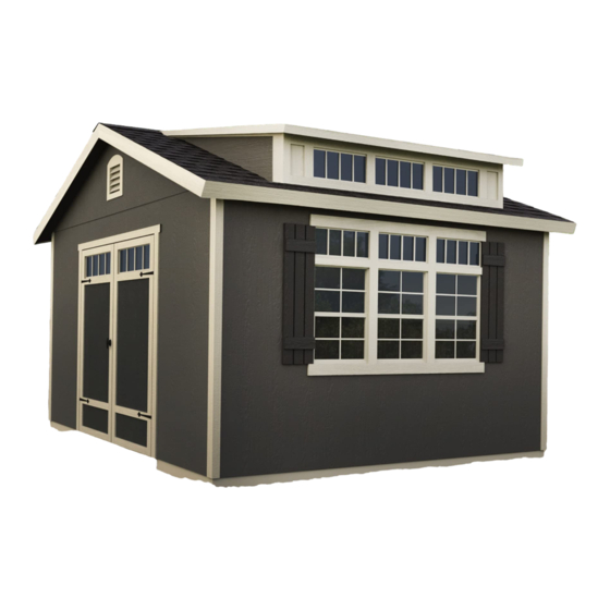
- Page 1 16519 02/28/2021 PART 2 GABLE 10' x 12' (305 x 366 cm) ACTUAL FLOOR SIZE IS 120 x 144" (304,8 x 365,8 cm) KEEP THIS MANUAL FOR FUTURE REFERENCE DOOR LOCATION OPTION ..continued from PART 1...
- Page 2 (Continued from PART 1, page 58.)
-
Page 3: Parts Required
GABLE PANELS PARTS REQUIRED: 1-1/2" (3,8 cm) 2 x 4 x 27-1/4" (5,1 x 10,2 x 69,2 cm) Make two upper gable assemblies; assembling on a flat surface is recommended. BEGIN Lay AFC on the flat side as shown. Place left gable panel on AFC and secure with 1-1/2" nails spaced evenly. 1-1/2"... - Page 4 GABLE FRAMING PARTS REQUIRED: 3" (7,6 cm) 2 x 4 x 4-7/8" (5,1 x 10,2 x 12,4 cm) 2 x 3 x 73-3/4" (5,1 x 7,6 x 187,3 cm) BEGIN Place FLM on top of CLA. Secure with 3" screws as shown (Fig. A, Fig. B). Ensure parts are flush to edge and corners.
- Page 5 GABLE UNITS PARTS REQUIRED: 3" (7,6 cm) 1-5/8" (4,1 cm) 2 x 4 x 4-3/8" x2 Gable Frame x2 Gable Assemblies (5,1 x 10,2 x 11,1 cm) Assemblies Arrange gable assemblies as shown (Fig. E). You will build (2) gable units. Ensure gable panel is flush at peak of gable frame assembly and flush along top edges.
- Page 6 GABLE UNITS PARTS REQUIRED: 3" (7,6 cm) 2" (5,1 cm) x2 Gable Units BEGIN Measure 1-1/2" down from top plate and mark at each side (Fig. A). Place gable unit on gable wall top plate. Hold secure with (1) 2" nail on each side as shown. BE SURE GABLE UNIT IS CENTERED ON WALL BEFORE NAILING.
- Page 7 RAFTERS PARTS REQUIRED: 3" (7,6 cm) Pre-assembled Pre-assembled rafter with 2 rafter with 1 gussets gusset ¸ BEGIN Install (2) rafters with 1 gusset on top plate, aligned over stud and at 23-5/8" measurement from inside of gable panel. Ensure rafter notch is tight to gable wall (Fig. B, Fig C). Secure rafter with (2) 3"...
- Page 8 DORMER WALL PARTS REQUIRED: 3" (7,6 cm) 2 x 4 x 13-3/16" (5,1 x 10,2 x 33,5 cm) 2 x 4 x 93-3/4" (5,1 x 10,2 x 28,1 cm) ¸ BEGIN Orient parts on edge on floor. Measure and mark. HINT: For easier nailing Secure with (2) 3"...
- Page 9 DORMER PARTS REQUIRED: 1-1/2" (3,8 cm) x1 Left x1 Right ¸ BEGIN Install dormer panels primed side out, resting on top plate and flush along bottom of rafter edge. Secure with 1-1/2" nails spaced evenly as shown. 1-1/2" (3,8 cm) Left Panel Nails Fig.
- Page 10 DORMER PARTS REQUIRED: 3" (7,6 cm) Pre-assembled dormer wall frame 1-1/2" (3,8 cm) Install assembled dormer frame flush with front top plate (Fig. B) and resting on wall. Ensure dormer wall frame is flush to front edges of installed dormer panels (Fig. C). Secure with 3"...
- Page 11 DORMER PARTS REQUIRED: 2" (5,1 cm) 3/8" x 20" x 94-1/2" (1,0 x 50,8 x 240 cm) Place 20" x 94-1/2" dormer panel primed side out and flush on top of wall panels. Ensure front dormer panel is flush with side panels along edge (Fig E). Secure front dormer panel with 2"...
- Page 12 DORMER PARTS REQUIRED: 3" (7,6 cm) TEMPORARY SPACER 3/8 x 2-1/2 x 23-1/4" (1 x 6,3 x 59,1 cm) 1-1/2" (3,8 cm) Pre-assembled dormer Pre-assembled dormer rafter with 1 gusset rafter with 1 gusset (for LEFT side) (for RIGHT side) Place left and right pre-assembled rafter (gusset facing in) resting on top of dormer frame and back wall top plate.
- Page 13 DORMER PARTS REQUIRED: 3" (7,6 cm) Pre-assembled dormer rafter with 2 gussets Install (2) outer rafters on dormer frame and back wall top plate. Align rafters at 21-3/8" (54,3 cm) measurement from inside of rafter (Fig. D). Secure rafters to dormer frame and back wall top plate with (2) 3" screws above notch (Fig. E, Fig. F). Install middle rafter on dormer frame and back wall top plate (Fig.
- Page 14 DORMER SOFFIT BLOCK PARTS REQUIRED: 3" (7,6 cm) 2 x 4 x 2-7/8" (5,1 x 10,2 x 7,3 cm) 2 x 4 x 94-1/2" (5,1 x 10,2 x 240 cm) Place (4) soffit block parts KDA and (2) UN on floor (Fig. B). Measure and mark. Secure with (2) 3"...
- Page 15 EAVE FRAMING PARTS REQUIRED: 3" (7,6 cm) 2 x 4 x 80-5/8" (5,1 x 10,2 x 204,8 cm) ¸ BEGIN Install eave fascia XMB flush to soffit frame center and gable outer framing, as shown. Attach at center first. Secure with 3" screws. Ensure flush to top of rafters and gable framing. Continue fastening XMB with 3"...
- Page 16 EAVE FRAMING (back side) PARTS REQUIRED: 3" (7,6 cm) 2 x 4 x 80-5/8" (5,1 x 10,2 x 204,8 cm) Install (2) eave fascia XMB flush to center rafter and gable framing, as shown. Attach at center first. Secure with 3" screws. Ensure flush to top of rafters and gable framing. Continue fastening XMB with 3"...
- Page 17 ROOF PANELS PARTS REQUIRED: x251 2" (5,1 cm) 3/4" GAUGE BLOCK 7/16 x 32-5/8 x 75-1/4" (1,1 x 82,9 x 191,1 cm) ▪ Install all roof panels with the grid lines facing up (rough side). ▪ Roof panels may cause serious injury until securely fastened. BEGIN Install the 32-5/8 x 75-1/4"...
- Page 18 ROOF PANELS PARTS REQUIRED: 7/16 x 48 x 96" 7/16 x 27-1/4 x 96" (1,1 x 121,9 x 243,8 cm) (1,1 x 69,2 x 243,8 cm) Install the 27-1/4" x 96" roof panel as shown. Use a gauge block to ensure the panel measures 3/4" (1,9 cm) on the rafter (Fig. D). Panel should be flush with eave frame (Fig.
- Page 19 ROOF PANELS PARTS REQUIRED: 7/16 x 32-5/8 x 75-1/4" (1,1 x 82,9 x 191,1 cm) Move up to the top of the roof and ensure accurate spacing between the centers of the rafters (Fig. E). Use a gauge block to ensure the panel measures 3/4" (1,9 cm) along the length of the rafter. Secure panel with (5) 2"...
- Page 20 ROOF PANELS PARTS REQUIRED: Secure all roof panels with 2" nails spaced 6" apart on edges and 12" apart inside panel. 6" (15,2 cm) 12" (30,5 cm) FINISH All panels are installed on the main roof.
- Page 21 ROOF PANELS (Dormer Side) PARTS REQUIRED: 7/16 x 33-3/8 x 75-1/4" 7/16 x 7-7/8 x 94-1/2" (1,1 x 84,8 x 191,1 cm) (1,1 x 20 x 240 cm) ▪ Install all roof panels with the grid lines facing up (rough side). ▪...
- Page 22 DORMER FELT / FLASHING PARTS REQUIRED: (x40) 1" GALVANIZED ROOFING NAILS (x4) 4" x 32" Aluminum #15 ROOFING FELT Flashing Cards (Optional) Pre-Bend 90 2" 2" Read roofing instructions beginning at Page 116 for roofing felt, drip edge, and shingle installation. Follow insructions below for dormer roofing felt and flashing installation.
- Page 23 DORMER FLASHING / SHINGLES PARTS REQUIRED: (x26) 5" x 7" Aluminum Flashing Cards 2-1/2" Pre-Bend 90 (x40) 1" GALVANIZED ROOFING NAILS 2-1/2" Trim, bend and nail a 5" x 7" flashing at the dormer corner (Fig. B). Secure flashing with 1" nails. Lay first row of shingles on top of flashing (Fig.
- Page 24 DORMER ROOF UNIT PARTS REQUIRED: 1-5/8" (4,1 cm) 2 x 6 x 35-5/8" (5,1 x 15,2 x 90,5 cm) 7/16 x 48 x 96" (1,1 x 121,9 x 243,8 cm) 2 x 6 x 67" (5,1 x 15,2 x 170,2 cm) BEGIN Place VV and BIB on flat surface.
- Page 25 DORMER SIDE SOFFIT ASSEMBLIES PARTS REQUIRED: 2" (5,1 cm) 2 x 4 x 52-1/2" (5,1 x 10,2 x 133,3 cm) 19/32 x 3-1/2 x 58-5/8" (1,5 x 8,9 x 148,9 cm) 19/32 x 3-1/2 x 58-5/8" (1,5 x 8,9 x 148,9 cm) Build a left and a right soffit assembly.
- Page 26 DORMER ROOF PARTS REQUIRED: 2" (5,1 cm) Pre-assembled DORMER ROOF UNIT ▪ Install all roof panels with the grid lines facing up (rough side). ▪ Roof panels may cause serious injury until securely fastened. BEGIN Lift and center the dormer roof unit on the dormer. Roof unit frame VV extends past dormer side panel by 4-1/8"...
- Page 27 DORMER ROOF PARTS REQUIRED: 2" (5,1 cm) 7/16 x 19-7/8 x 96" (1,1 x 50,5 x 243,8 cm) Install the 19-7/8 x 96" panel flush to the installed panel. Mark rafter locations on the panel and secure with 2" nails spaced 6" apart along panel edges and 12"...
- Page 28 DORMER ROOF PARTS REQUIRED: 2" (5,1 cm) 3" (7,6 cm) Pre-assembled SOFFIT UNIT (Right) Pre-assembled SOFFIT UNIT (Left) Place SOFFIT UNIT tight against dormer wall and flush with front soffit board (Fig. B). Secure SOFFIT UNIT with 2" screws (Fig. C). Toe-screw soffits together with 3"...
- Page 29 DORMER ROOF PARTS REQUIRED: 1-5/8" (4,1 cm) 7/16 x 3-7/16 x 64-1/2" (1,1 x 8,7 x 163,8 cm) Place 3-7/16" x 64-1/2" dormer roof panels on either side of installed dormer roof panels. Hold flush to front and along panel seam. Secure with 1-5/8"...
- Page 30 DORMER FASCIA PARTS REQUIRED: 2" (5,1 cm) 19/32 x 2-1/2 x 60" (1,5 x 6,3 x 152,4 cm) 19/32 x 2-1/2 x 43-13/16" (5,1 x 10,2 x 111,3 cm) 19/32 x 2-1/2 x 64-1/2" (1,5 x 6,3 x 163,8 cm) 19/32 x 2-1/2 x 64-1/2"...
- Page 31 DORMER WINDOWS PARTS REQUIRED: 3/4" (1,9 cm) ¸ BEGIN Seal windows with high-quality exterior-grade caulk before installing. Secure windows with 3/4" screws as shown. (4) 3/4" screws per window HINT: Caulk behind frame near edge before installing. You must caulk around windows to validate warranty. FINISH Your dormer windows are now installed.
- Page 32 DORMER TRIM PARTS REQUIRED: 1-1/4" (3,2 cm) 19/32 x 2-1/2 x 46-9/16" (1,5 x 6,3 x 118,3 cm) 19/32 x 2-1/2 x 46-9/16" (1,5 x 6,3 x 118,3 cm) Install AMR flush to MFR and QNR. Secure with 1-1/4" screws, evenly spaced. Repeat step to install AML on dormer left side.
- Page 33 DORMER WINDOW TRIM PARTS REQUIRED: 2" (5,1 cm) 1-1/4" (3,2 cm) 19/32 x 3-1/2 x 9-1/8"" (1,5 x 8,9 x 23,2 cm) 19/32 x 2-1/2 x 90-9/16" (1,5 x 6,3 x 230 cm) 19/32 x 2-1/2 x 15-1/8" 19/32 x 3-1/2 x 90-9/16" (1,5 x 8,9 x 230 cm) (1,5 x 6,3 x 38,4 cm) Install all dormer trim parts with primed side facing out.
- Page 34 GABLE END SOFFITS PARTS REQUIRED: 2" (5,1 cm) 3/8 x 7-7/8 x 73-5/16" (1 x 20 x 186,2 cm) Install all soffit boards with the primed side facing down. Ensure soffit boards are lined-up at seam (Fig. B) and at peak (Fig. D). BEGIN Install right 73-5/16"...
- Page 35 EAVE SIDE SOFFITS PARTS REQUIRED: 2" (5,1 cm) 3/8 x 5-7/8 x 72-3/4" (1 x 14,9 x 184,8 cm) Install all soffit boards with the primed side facing down. Ensure soffit boards are flush at rafter ends (Fig. C) and flush at seams. BEGIN Starting at the center rafter, install 72-3/4"...
- Page 36 EAVE SIDE SOFFITS (dormer side) PARTS REQUIRED: 2" (5,1 cm) 3/8 x 5-7/8 x 72-3/4" (1 x 14,9 x 184,8 cm) Install all soffit boards with the primed side facing down. Ensure soffit boards are flush at rafter ends (Fig. C) and flush at seams. Starting in the middle of the eave framing, install 72-3/4"...
- Page 37 GABLE FASCIA PARTS REQUIRED: 2" (5,1 cm) 3/8 x 4-3/4 x 76-1/8" (1 x 12,1 x 193,4 cm) 3/8 x 4-3/4 x 76-1/8" (1 x 12,1 x 193,4 cm) Install all fascia boards with the primed side facing out. BEGIN Position fascia with primed side out and flush to peak and roof panels as shown (Fig.
- Page 38 EAVE SIDE FASCIA PARTS REQUIRED: 2" (5,1 cm) 3/8 x 4-3/4 x 72" (1 x 12,1 x 182,9 cm) 3/8 x 4-3/4 x 89-1/4" (1 x 12,1 x 226,7 cm) Install all fascia boards with the primed side facing out. BEGIN Position 72"...
- Page 39 DOORS PARTS REQUIRED: 3" (7,6 cm) 69" (175,3 cm) Door Stiffener 1-5/8" (4,1 cm) 1 x 3 x 5" (2,5 x 7,6 x 12,7 cm) Left Door Assembled Right Door Assembled BEGIN Orient parts as shown on flat surface. 3/8" offset is to top. Look for red (right) and green (left) on hinge board.
- Page 40 DOORS (eave or gable wall) PARTS REQUIRED: 3" (7,6 cm) TEMPORARY SUPPORT 69” (175,3) Door Stiffener Install OO flush under panels. Secure to floor frame with (2) 3" screws (Fig. A) . Fig. A Flush against wall panels TEMPORARY SUPPORT Center doors on panel seam as shown (Fig.
- Page 41 DOOR TRIM PARTS REQUIRED: 2" (5,1 cm) 3/4" (1,9 cm) 19/32 x 2-1/2 x 22-5/8" (2,5 x 6,3 x 57,5 cm) 19/32 x 2-1/2 x 63" (2,5 x 6,3 x 160 cm) BEGIN Reinforce the door trim with 3/4" screws through door panel into trim (Fig. A, Fig. B). Attach horizontal door rails FA with 3/4"...
-
Page 42: Front Side View
DOOR TRANSOM WINDOWS PARTS REQUIRED: 3/4" (1,9 cm) Transom Window ¸ BEGIN Apply high quality exterior-grade caulk behind frame near edge before installing to seal window. You must caulk completely around window frame and all exposed door panel edges and trim to validate your warranty. Use a paintable exterior rated caulk. - Page 43 DOOR STIFFENERS PARTS REQUIRED: 2" (5,1 cm) 69” (175,3) Door Stiffener BEGIN Center OO’s vertically on the left and right doors as shown (Fig. A, Fig. B). Secure with (7) 2" screws through outside trim into OO (Fig. B). Center OO in door opening.
-
Page 44: Door Hardware
DOOR HARDWARE PARTS REQUIRED: 1" (2,5 cm) 5/16" (0,8 cm) Drill Bit BEGIN Place spring bolt on OO in open position with bolt end 3/8" down from frame. Bolt is open when loop is contacting base (Fig A) . Mark and pre-drill holes for screws. Install bolt with screws supplied and drill 5/16"... -
Page 45: Right Door
DOOR HARDWARE / DECORATIVE HINGES PARTS REQUIRED: 1-1/2" (3,8 cm) 3/8" (10,9 cm) Drill Bit 3/4" (1,9 cm) 1/4" (0,6 cm) Drill Bit BEGIN Measure and mark location of hole on outside of right door as shown (Fig. A) . Pre-drill hole with 1/4"... - Page 46 CORNER TRIM PARTS REQUIRED: 2" (5,1 cm) 3/8 x 1-3/4 x 82-1/2" (1 x 4,4 x 209,6 cm) 3/8 x 1-3/4 x 81-3/4" (1 x 4,4 x 207,6 cm) ¸ BEGIN Install (1) 81-3/4" trim board flush under soffit panel and against eave wall with (1) 2"...
- Page 47 LOFT PARTS REQUIRED: 3" (7,6 cm) 2 x 4 x 24" (5,1 x 10,2 x 61 cm) 7/16" (11 mm) Drill Bit 2 x 4 x 96" (5,1 x 10,2 x 243,8 cm) ¸ BEGIN Orient parts TP and RL on a flat surface. Hold parts TP and RL flush and aligned. Assemble joist with 3"...
- Page 48 LOFT PARTS REQUIRED: 7/16" (11 mm) Drill Bit 3" (7,6 cm) (NOT ACTUAL SIZE) 2 x 4 x 24" (5,1 x 10,2 x 61 cm) 3/8" x5-1/2" (1 cm x 14 cm) Hex Bolt 3/8" (1 cm) 2 x 4 x 96" (5,1 x 10,2 x 243,8 cm) Flat Washer Pre-Assembled Loft Joist 3/8"...
- Page 49 LOFT PARTS REQUIRED: 2" (5,1 cm) 23-7/8" x 96" (60,6 x 243,8cm) Install loft panel centered over loft joists. Secure with 2" (5,1 cm) nails 8" (20,3 cm) apart. There will be a gap of approximately 8-1/2" on either side. 8 "...
- Page 50 SHELF PARTS REQUIRED: 2" (5,1 cm) 2 x 3 x 6-5/8" (5,1 x 7,6 x 16,8 cm) 3/8 x 7-1/2 x 10-1/8" (1 x 19,1 x 25,7 cm) NOTE: Install the bench, shelf and loft on the gable wall farthest from the door location. BEGIN Secure PHA to bracket panels with (3) 2"...
- Page 51 SHELF PARTS REQUIRED: 2" (5,1 cm) 7/16 x 7-7/8 x 96" (1,1 x 20 x 243,8 cm) 7/16 x 7-7/8 x 23-7/8" (1,1 x 20 x 60,6 cm) 1 x 4 x 96" (2,5 x 10,2 x 243,8 cm) 1 x 4 x 23-7/8" (2,5 x 10,2 x 60,6 cm) Install shelf panels centered over shelf supports.
-
Page 52: Work Bench
WORK BENCH PARTS REQUIRED: 2" (5,1 cm) 2 x 3 x18-3/4" (5,1 x 7,6 x 47,6 cm) 3/8 x 14-1/4 x 22-1/4" (1 x 36,2 x 56,5 cm) BEGIN Secure LMA to bracket panels with (3) 2" nails. Assemble 6 shelf supports as shown; 5 right-side, 1 left-side. Flush 2"... - Page 53 WORK BENCH PARTS REQUIRED: 2" (5,1 cm) 7/16 x 20-3/4 x 92-1/2" (1,1 x 52,7 x 235 cm) 7/16 x 20-3/4 x 20-1/2" (1,1 x 52,7 x 52,1 cm) 1 x 4 x 96" (2,5 x 10,2 x 243,8 cm) 1 x 4 x 23-7/8"...
- Page 54 SHUTTERS ASSEMBLY PARTS REQUIRED: 1" (2,5 cm) 19/32 x 3-1/2 x 11-3/8" (1,5 x 8,9 x 28,9 cm) 19/32 x 3-1/2 x 41-1/2" (1,5 x 8,9 x 105,4 cm) BEGIN Position shutter parts EHT primed side-down on floor as shown. Primed side down Fasten slats RGD to EHT with 1"...
- Page 55 LARGE WINDOWS PARTS REQUIRED: 1-5/8" (4,1 cm) BEGIN Place window in center of window cutout as shown. Fig. A Seal window by caulking behind frame with high-quality exterior-grade caulk before installing. Secure window with (4) 1-5/8" screws as shown. Ensure window is level. Repeat to install (2) more large windows.
- Page 56 TRANSOM WINDOWS PARTS REQUIRED: 3/4" (1,9 cm) 9" x 27" (22,8 x 68,5 cm) ¸ BEGIN Seal windows with high-quality exterior-grade caulk before installing. Secure windows with 3/4" screws as shown. HINT: Caulk behind frame near edge before installing. 3/4" Screws per window You must caulk around windows to validate your warranty.
- Page 57 WINDOW TRIM PARTS REQUIRED: 2" (5,1 cm) 19/32 x 3-1/2 x 41-1/2" (1,5 x 8,9 x 105,4 cm) 19/32 x 3-1/2 x 77-1/4" (1,5 x 8,9 x 196,2 cm) Install all window trim parts with primed side facing out. Do not nail in metal window frames. BEGIN Measure up from bottom edge of lower window and mark, as shown.
- Page 58 WINDOW TRIM & SHUTTERS PARTS REQUIRED: 2" (5,1 cm) 19/32 x 2-1/2 x 22-1/4" (5,1 x 6,3 x 56,5 cm) 19/32 x 3-1/2 x 77-1/4" (1,5 x 8,9 x 196,2 cm) Pre-assembled shutter Install (3) FF centered and level between windows, flush to IDA. Secure with 2"...
- Page 59 GABLE VENTS PARTS REQUIRED: 1" (2,5 cm) ¸ BEGIN Install (1) vent in each gable. Caulk behind vent flanges. Secure with 1" screws. FINISH Your gable vents are installed.
- Page 60 PAINT & CAULK - NOT INCLUDED - • Use acrylic latex caulk that is paintable. Caulk at all horizontal and vertical seams, between the trim and walls, and all around the door trim. • Use a high quality exterior acrylic latex paint. When painting your building, there are a few key areas that can be easily overlooked that must be painted: •...
- Page 61 SHINGLES - NOT INCLUDED - • Follow directions provided by manufacturer and these instructions. Familiarize yourself with a 3-Tab Shingle. Notch Notch SHINGLE NAIL PATTERN 1/2 " 1" Sealing Str 1" (1,3 cm) (2,5 cm) (2,5 cm) Half A Rain Slot Full Rain Slot NAILS NEVER DRIVE FASTENERS INTO OR ABOVE SEALING STRIPS.
- Page 62 SHINGLES continued... Beginning at front of shed, install first row of shingles with notch at 1" past roof edge or flush with drip edge. Roof Deck FRONT OF BACK OF SHED SHED 1" (2,5 cm) Flush with starter row. Notch - or - Drip Edge Flush with starter row.
- Page 63 SHINGLES continued... Continue installing rows of shingles to the peak. At the peak make sure there is a maximum of 5" or less to the rain slot, as shown below. If shingles overlap at ridge cut to peak with a utility knife. 5"...
- Page 64 SHINGLES - RIDGE CAP • You will finish off the top of the roof with a ridge cap made from shingles. BEGIN Cut shingles into (3) pieces. Hint: Use cut-off pieces first. 2" 2" (5 cm) (5 cm 2" 2" 2"...
- Page 65 SHINGLES - RIDGE CAP continued... Continue installing ridge cap to back of roof. Make sure there is 4" between the shingle-color and edge of shingles. 4" (10 cm) Trim cap off flush to shingles When you have 4" minimum of shingle color cut (1) piece to cap your roof. Cut at top of rain slot.
- Page 66 LIMITED CONDITIONAL WARRANTY* Backyard Storage Solutions, LLC warrants the following: Every product is warranted from defects in workmanship and manufacturing for 1 year. All accessories, hardware and metal components are warranted for 2 years. All Oriented Strand Board (OSB) is warranted for 2 years Siding and Trim is warranted for 15 years.
Need help?
Do you have a question about the GABLE 10 x 12 and is the answer not in the manual?
Questions and answers