Table of Contents
Advertisement
Quick Links
For questions on assembly or for general inquiries, you may contact us in the following ways:
Call a Recruiter Today! 734-365-7000
Flexible schedule
*based on number of completed installations
Call Us First!
DO NOT RETURN TO STORE.
Call customer service: 1-734-242-6900
AVOID THE WAIT!
visit us online at
help.backyardproducts.com
Submit a help request
Answers to frequently asked questions
Live chat with an agent
Did you enjoy building your shed?
JOIN OUR TEAM
AND MAKE UP TO $1,500/WEEK*
No selling,
just building
Bonus incentives
available
16909-A
Advertisement
Table of Contents

Subscribe to Our Youtube Channel
Related Manuals for Backyard Products COSMOPOLITAN 10x4


Summary of Contents for Backyard Products COSMOPOLITAN 10x4
- Page 1 16909-A Call Us First! DO NOT RETURN TO STORE. For questions on assembly or for general inquiries, you may contact us in the following ways: Call customer service: 1-734-242-6900 AVOID THE WAIT! visit us online at help.backyardproducts.com Submit a help request Answers to frequently asked questions Live chat with an agent Did you enjoy building your shed?
- Page 2 (This page intentionally left blank.)
-
Page 3: Assembly Manual
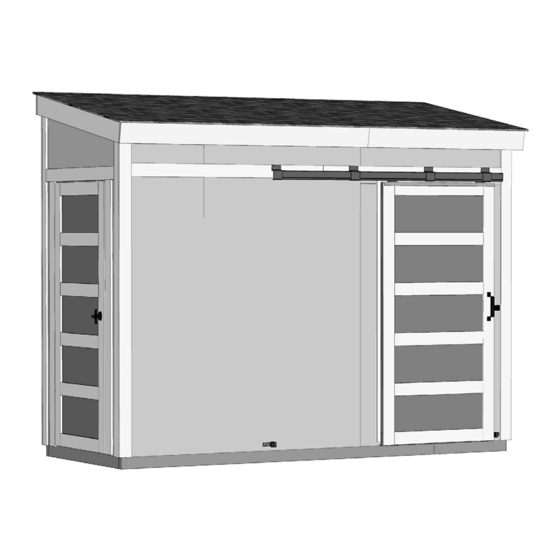
16909-A 10/24/2022 ASSEMBLY MANUAL COSMOPOLITAN 10' x 4' (304,8 cm x 121,9 cm) ACTUAL FLOOR SIZE IS 120" x 48" (304,8 cm x 121,9 cm) KEEP THIS MANUAL FOR FUTURE REFERENCE Three options for door trim. IM PORTAN T ! READ INSTRUCTIONS THOROUGHLY PRIOR TO BEGINNING ASSEMBLY. - Page 4 TOOLS Required Optional K Phillips K Tool Belt/ K Utility Knife Screwdriver Nail Pouch K Shingle Blades K Drill / Driver K Tin Snips K 3/8" Drill Bit K Caulk Gun (for drip edge) K #2 Philips Drive Bit K Chalk Line K Hammer K Paint Tools K Level...
-
Page 5: Optional Materials
ADDITIONAL MATERIALS NEEDED FOUNDATION OR FLOOR MATERIALS • This shed kit includes a complete wood floor frame system. • This shed kit does not include ANY leveling materials. • See the FLOOR LEVELING section on page 9 for recommended methods and suggested materials to properly level your foor, as this will vary depending on your specific site. -
Page 6: Parts List
PARTS IDENTIFICATION AND SIZES Part identification WOOD SIZE CONVERSION CHART Treated lumber is stamped: is stamped on some parts. Nominal Board Size Actual Size 2 x 4 ....1-1/2" x 3-1/2" (3,8 x 8,9 cm) 1 x 4 ....3/4" x 3-1/2" (1,9 x 8,9 cm) 2 x 3 ....1-1/2"... - Page 7 PARTS LIST 19/32" x 3-1/2" x 2-7/16" (1,5 x 8,9 x 6,2 cm) 19/32" x 5-1/2" x 50-1/2" (1,5 x 14 x 128,3 cm) 19/32" x 5-1/2" x 54" (1,5 x 14 x 137,2 cm) 19/32" x 5-1/2" x 54" (1,5 x 14 x 137,2 cm) 19/32"...
- Page 8 WALL PANELS & DOORS Wall panels are 3/8" (1,0 cm) thick. NOTE: Panel parts are not stamped. 24 x 84" 48 x 84" 8-1/2 x 72" 48 x 76" 36" (91,4 cm) (61 x 213,3 cm) (121,9 x 213,3 cm) (21,6 x 182,9 cm) (121,9 x 193 cm) DOOR...
-
Page 9: Shelf Parts
FLOOR PANELS Pro-struct foor panels are 5/8" (1,6 cm) thick. NOTE: Panel parts are not stamped. 48" x 96" 48" x 23-7/8" (121,9 x 243,8 cm) (121,9 x 60,6 cm) SHELF PARTS 2 x 3 x 5-3/4" (5,1 x 7,6 x 14,6 cm) 2 x 3 x 8-3/4"... - Page 10 DOOR HARDWARE (Not Actual Size) T-Handle 1-1/2" (3,8 cm) (2 screws in package) 1" (2,5 cm) #14 x 1" (2,5 cm) 1-1/4" (3,2 cm) #12 2" (5,1 cm) 1" (2,5 cm) 5/16" x 2" Hex Lag Screw 5/16" x 1" Hex Lag Screw 36"...
- Page 11 FLOOR LEVELING OPTIONS There are multiple ways to level your floor frame. Our recommended leveling method is shown below. Leveling materials are not included in this kit. PREFERRED METHOD - 4x4 TREATED RUNNERS • 3" Screw angled into 4x4. • (2) at each connection. 6"...
- Page 12 CONCRETE FOUNDATION If you choose to install your kit on a concrete slab refer to the diagram below. Treated Sill Plate Caulk between sill plate and concrete. 3-1/2" (8,9 cm) 4" (10,2 cm) Building Size Actual Floor Size 4'x10' (121,9 x 304,8 cm) 4'x10' (121,9 x 304,8 cm) 120"...
- Page 13 COMPONENT SECTION INDEX Description Section Page Floor Walls Shelf Rafters Roof Panels Trim Doors & Door Trim Door HDW. Shingles/Roofing ..............59...
-
Page 14: Parts Required
FLOOR FRAME PARTS REQUIRED: 3" (7,6 cm) 2 x 4 x 24" (5 x 10 x 61 cm) 2 x 4 x 45" (5 x 10 x 114,3 cm) 2 x 4 x 96" (5 x 10,2 x 243,8 cm) BEGIN Arange parts on edge on a fl at surface. - Page 15 FLOOR FRAME LEVEL AND SQUARE FLOOR FRAME Before installing the fl oor decking, it is important to level and square the fl oor frame. A level and square fl oor frame is required to correctly construct your shed. BEGIN See page 9 for the preferred fl oor leveling method. Use level and check the frame is level before installing fl oor panels.
- Page 16 FLOOR PANELS PARTS REQUIRED: 2" (5,1 cm) 48 x 96" 48 x 23-7/8" (121,9 x 243,85 cm) (121,9 x 60,6 cm) Ensure your f oor frame is square by installing panel and squaring frame. BEGIN Install the 48" x 96" pro-struct panel with the 48" edge and corner fl ush to the fl oor frame (Fig A). Secure panel with (2) 2"...
- Page 17 IMPORTANT! Check that the foor frame is level after installing foor panels. Re-level if needed. • The foor may be used as a stable work surface for wall construction. HINT: • Organize your assembly procedure during the build process to avoid over-handling of the walls.
- Page 18 DOOR HEADER Assemble this door header before building any walls! PARTS REQUIRED: 3" (7,6 cm) 7/16" x 3-1/4" x 33-5/8" (1,1 x 8,3 x 85,4 cm) OSB 2 x 4 x 33-5/8" (5,1 x 10,2 x 85,4 cm) BEGIN Place (1) BZM and OSB end-to-end on fl at surface, fl ush in middle. Center OSB on top of BZM.
- Page 19 WALL PANEL INSTALLATION HINTS & EXAMPLES PARTS REQUIRED: 2" (5,1 cm) 3/4" Measuring Guide 3/8 x 48 x 76" (1 x 121,9 x 193 cm) Ensure your wall is square by installing one panel and squaring frame. Install all wall panels with the primed side facing up. BEGIN 2 Nails Place a 48"...
- Page 21 FRONT WALL FRAME PARTS REQUIRED: 3" (7,6 cm) Beveled Profi le 2 x 4 x 48" (5,1 x 10,2 x 121,9 cm) 3" (7,6 cm) Beveled Profi le 2 x 4 x 72" (5,1 x 10,2 x 182,9) 2 x 4 x 72" (5,1 x 10,2 x 182,9 cm) 2 x 4 x 80-5/8"...
- Page 22 FRONT WALL PANELS PARTS REQUIRED: x173 2" (5,1 cm) 11-7/8 x 48" (30,2 x 121,9 cm) 8-1/2 x 72" (21,6 x 182,9 cm) 24 x 84" (61 x 213,3 cm) 48 x 84" (121,9 x 213,3 cm) For squareness maintain 3/4" Flush measurement along panel edge.
- Page 23 BACK WALL FRAME PARTS REQUIRED: 3" (7,6 cm) 2 x 4 x 48" (5,1 x 10,2 x 121,9 cm) 2 x 4 x 72" (5,1 x 10,2 x 182,9 cm) 2 x 4 x 88-1/2" (5,1 x 10,2 x 224,8 cm) Beveled 2 x 4 x 48"...
- Page 24 BACK WALL PANELS PARTS REQUIRED: x144 2" (5,1 cm) 23-7/8 x 96" 48 x 96" (60,6 x 243,8 cm) (121,9 x 243,8 cm) For squareness maintain 3/4" BEGIN measurement along panel edge. 3-1/2" 3-1/2" (15,2 cm) above bevel. 3/4" BEGIN HERE (1,9 cm) Install (1) 48"...
- Page 25 LEFT SIDE WALL PARTS REQUIRED: 3" (7,6 cm) 2 x 6 x 31-5/16" (5,1 x 15,2 x 81,1 cm) 1-1/2" (3,8 cm) 2 x 4 x 84-9/16" (5,1 x 10,2 x 214,8 cm) 20" x 48" (50,8 x 121,9 cm) 2 x 4 x 90-11/16"...
-
Page 26: Right Side Wall
RIGHT SIDE WALL PARTS REQUIRED: 3" (7,6 cm) 1-1/2" (3,8 cm) 20" x 48" (50,8 x 121,9 cm) 2 x 4 x 41" (5,1 x 10,2 x 104,1 cm) 48 x 76" (121,9 x 193 cm) 2 x 4 x 73-1/4" (5,1 x 10,2 x 186,1 cm) BEGIN Install panels to the measurements shown, Arrange parts on fl at sides on a fl at... -
Page 27: Back Wall Installation
BACK WALL INSTALLATION PARTS REQUIRED: 3" (7,6 cm) 2" (5,1 cm) TEMPORARY SUPPORT 3" (7,6 cm) 2 x 4 x 53-1/2" (5,1 x 10,2 x 135,9 cm) 3-1/2" BEGIN (8,9 cm) Center back wall on the fl oor. The 3-1/2" measurement is at the top. Install MJC as a temporary brace. - Page 28 FRONT WALL INSTALLATION PARTS REQUIRED: 2" (5,1 cm) 3" (7,6 cm) 3" (7,6 cm) TEMPORARY SUPPORT 2 x 4 x 53-1/2" (5,1 x 10,2 x 135,9 cm) BEGIN Center back wall on the fl oor. The 3-1/2" measurement is at the top. Install MJC as a temporary brace.
- Page 29 RIGHT WALL INSTALLATION PARTS REQUIRED 1-1/2" (3,8 cm) 3" (7,6 cm) 2" (5,1 cm) 3" (7,6 cm) 2" (5,1 cm) 2" (5,1 cm) BEGIN Screws Center right wall on the fl oor. Flush wall panel to front and back panel edges. ENSURE PANEL CORNERS ARE FLUSH.
- Page 30 LEFT WALL INSTALLATION PARTS REQUIRED 1-1/2" (3,8 cm) 3" (7,6 cm) 2" (5,1 cm) 2" (5,1 cm) BEGIN Center left wall on the fl oor. 2" (5,1 cm) Flush wall panel to front and back Screws panel edges. ENSURE PANEL CORNERS ARE FLUSH. ENSURE 31-5/16"...
- Page 31 SHELF PARTS REQUIRED 3" (7,6 cm) 2 x 3 x 5-3/4" (5,1 x 7,6 x 14,6 cm) 2 x 3 x 8-3/4" (5,1 x 7,6 x 22,2 cm) 2 x 3 x 93-3/4" (5,1 x 7,6 x 238,1 cm) BEGIN Arrange parts on edge on a flat surface.
- Page 32 SHELF PARTS REQUIRED: 3" (7,6 cm) 8" x 12-1/2" (20,3 x 31,8 cm) Pre assembled shelf frame 1-1/2" (3,8 cm) 3/8" x 9" x 96" (1,0 x 22,9 x 243,8 cm) Flush 3" (7,6 cm) Screws Measure up from fl oor and mark 76-3/4" on back wall stud.
- Page 33 RAFTERS PARTS REQUIRED: 1-1/2" (3,8 cm) 3" (7,6 cm) 2 x 4 x 53-1/2" (5,1 x 10,2 x 135,9 cm) 3/8" x 3-1/2" x 3-1/2" (1,5 x 6,3 x 6,3 cm) BEGIN MEASURE FROM MEASURE BETWEEN RAFTERS INSIDE PANEL Measure and mark locations for rafters. 96"...
- Page 34 RAFTERS PARTS REQUIRED: 3" (7,6 cm) 2 x 4 x 53-7/8" (5,1 x 10,2 x 136,8 cm) Flush 3" (7,6 cm) Screws Flush Flush Install outer rafter IVB fl ush along top of wall panel and fl ush to back wall panel. Secure IVB with 3"...
- Page 35 ROOF PANELS PARTS REQUIRED: 2" (5,1 cm) 3/4" Measurement 48 x 96" guide (121,9 x 243,8 cm) Install all roof panels with the rough side facing up. Roof panels may cause serious injury until securely fastened. BEGIN Place the 48" x 96" roof panel as shown. Use a 3'4"...
- Page 36 ROOF PANELS PARTS REQUIRED: 1-7/8 x 53-1/2" 2" (5,1 cm) 5-1/2 x 23-7/8" (4,8 x 135,9 cm) (14 x 60,6 cm) 48" x 23-7/8" (121,9 x 60,6 cm) 5-1/2 x 96" (14 x 243,8 cm) Install the 48" x 23-7/8" panel fl ush to the installed panel and fl ush to front of rafters. Secure with (1) 2"...
- Page 37 SOFFIT TRIM PARTS REQUIRED: 2" (5,1 cm) 3/8" x 1-1/2" x 49-1/2" (1 x 3,8 x 125,7 cm) 3/8" x 3-11/16 x 49-7/8" (1 x 9,4 x 126,7 cm) 3/8" x 3-11/16 x 73-7/8" (1 x 9,4 x 187,6 cm) Install all trim with the primed side facing out.
-
Page 38: Right Side
SIDE FACIA TRIM PARTS REQUIRED: 2" (5,1 cm) 19/32" x 5-1/2" x 54" (1,5 x 14 x 137,2 cm) 19/32" x 5-1/2" x 54" (1,5 x 14 x 137,2 cm) Install all trim with the primed side facing out. BEGIN Install SZA and QCC gable fascia flush end of rafter and flush to roof panel. - Page 39 FRONT FACIA TRIM PARTS REQUIRED: 2" (5,1 cm) 19/32" x 5-1/2" x 50-1/2" (1,5 x 14 x 128,3 cm) 19/32" x 5-1/2" x 74-7/16" (1,5 x 14 x 189,1 cm) BEGIN Install UAC and VOA front fascia trim to rafters. Flush to trim to roof panels. Begin installing at seam (Fig.
- Page 40 RIGHT SIDE TRIM PARTS REQUIRED: 2" (5,1 cm) 19/32" x 3-1/2" x 43-3/4" (1,5 x 8,9 x 145,9 cm) 19/32" x 2-1/2" x 84" (1,5 x 6,3 x 213,4 cm) 19/32" x 2-1/2" x 92-1/8" (1,5 x 6,3 x 234 cm) Install all trim with the primed side facing out.
-
Page 41: Left Side
LEFT SIDE TRIM PARTS REQUIRED: 2" (5,1 cm) 19/32" x 2-1/2" x 84" (1,5 x 6,3 x 213,4 cm) 19/32" x 2-1/2" x 92-1/8" (1,5 x 6,3 x 234 cm) Install all trim with the primed side facing out. BEGIN Install trim to the left wall as shown. - Page 42 BACK WALL TRIM PARTS REQUIRED: 2" (5,1 cm) 19/32" x 5-1/2" x 50-1/2" (1,5 x 14 x 128,3 cm) 19/32" x 5-1/2" x 74-7/16" (1,5 x 14 x 189,1 cm) 19/32" x 3-1/2" x 90-15/16" (1,5 x 4,4 x 231 cm) BEGIN Install UAC and VOA trim to back wall flush to side fascia trim.
- Page 44 SIDE DOOR and DOOR TRIM PARTS REQUIRED: 2" (5,1 cm) 19/32" x 3-1/2" x 43-3/4" (1,5 x 8,9 x 145,9 cm) 31-5/8" (80,3 cm) 19/32" x 3-1/2" x 72-3/8" (1,5 x 8,9 x 183,8 cm) SIDE DOOR 2" (5,1 cm) BEGIN Finishing Nails Flush ZP with bottom wall panel and level (plumb).
- Page 45 SIDE DOOR RAILS - OPTION 1 PARTS REQUIRED: 2" (5,1 cm) 3/4" (1,9 cm) 19/32" x 3-1/2" x 10-1/8" 19/32" x 3-1/2" x 24-5/8" (1,5 x 8,9 x 62,5 cm) (1,5 x 8,9 x 25,7 cm) See next page for side door rails Option 2. BEGIN Install (4) 3-1/2"...
- Page 46 SIDE DOOR RAILS - OPTION 2 PARTS REQUIRED: 2" (5,1 cm) 19/32" x 3-1/2" x 10-1/8" 3/4" (1,9 cm) (1,5 x 8,9 x 25,7 cm) 19/32" x 3-1/2" x 24-5/8" (1,5 x 8,9 x 62,5 cm) 19/32" x 55-1/16" x 28-1/2" (1,5 x 8,9 x 139,9 cm) BEGIN Install (1) 3-1/2"...
- Page 47 SIDE DOOR STIFFENER PARTS REQUIRED: 2" (5,1 cm) 69" (175,3 cm) Door Stiffener Door stiffener installation is for all side door trim options. BEGIN Fig. A Center OO vertically on door in the door opening (Fig. A), 1-5/8" from edge of door (Fig.
- Page 48 SIDE DOOR HARDWARE PARTS REQUIRED: 1/2" (13 mm) Drill Bit 31-3/16" Metal Threshold 1/4" (6 mm) Drill Bit 1-1/2" (3,8 cm) 3/4" (1,9 cm) x6 Bagged separately / special coating BEGIN Measure and mark location of hole on outside of right door (Fig .A). Pre-drill pilot hole with 1/4"...
- Page 49 DOOR TRACK and THRESHOLD PARTS REQUIRED: 30-1/2" Metal Threshold 5/16" x 2" 3/4" (1,9 cm) x6 (8m x 5,1 cm) Bagged separately / special coating 1/8" BIT (3 mm) 5/16" x 1" (8m x 2,5 cm) ¸ BEGIN Align top of track brackets fl ush to top of horizontal trim and fl ush to right corner trim. Mark bracket-hole locations on horizontal trim.
- Page 50 FRONT DOOR REINFORCEMENT PARTS REQUIRED: 1-1/4" (3,2 cm) 19/32" x 3-1/2" x 36" (1,5 x 8,9 x 91,4 cm) 19/32" x 3-1/2" x 65" (1,5 x 8,9 x 165,1 cm) ¸ BEGIN Reinforce the back of the front door by installing (2) JQC and (2) IDC. Flush parts at all corners, edges and seams.
- Page 51 FRONT DOOR HARDWARE Metal Rain Channel (drip edge) PARTS REQUIRED: 1" x 1" x 36" (2,5 x 2,5 x 191,4 cm) #8 x 3/4" (1,9 cm) Self-Piercing Round Head Screws Door J-Channel 1-1/4" x 7/16" x 36" (3,2 x 1,1 x 91,4 cm) #8 x 1"...
- Page 52 FRONT DOOR TRIM - OPTION 1 & 2 PARTS REQUIRED: 2" (5,1 cm) 3/4" (1,9 cm) 36" (91,4 cm) 19/32" x 3-1/2" x 10-1/8" FRONT DOOR (1,5 x 8,9 x 25,7 cm) 19/32" x 3-1/2" x 29" (1,5 x 8,9 x 73,3 cm) 19/32"...
-
Page 53: Door Hardware
DOOR HARDWARE PARTS REQUIRED: 36" (91,4 cm) Door Brush #8 x 1" (2,5 cm) Wide Head Metal Screws ¸ BEGIN Install 36" door brush to bottom of door, flush channel across outside of door (Fig. C). Secure brush channel with 1" self-drilling screws, spaced evenly. Flush 1"... - Page 54 DOOR TROLLEYS PARTS REQUIRED: 1" (2,5 cm) ¸ BEGIN Install (2) rolling door trolleys to inside top of door. Secure trolleys screws supplied in rolling door hardware bag. Position as shown. 5-3/8" 5-3/8" (13,7 cm) (13,7 cm) INSIDE OF DOOR TAB fush to top of door...
-
Page 55: Door Installation
DOOR INSTALLATION PARTS REQUIRED: BEGIN Slide door into track, as shown (Fig. A). Fig. A NOTE: Install door into track slowly to prevent damage to rain channel. - Page 56 DOOR HARDWARE PARTS REQUIRED: 2" (5,1 cm) 1/8" BIT 1" (2,5 cm) (3,0 mm) 19/32" x 3-1/2" x 2-7/16" (1,5 x 8,9 x 6,2 cm) #14 x 1" (2,5 cm) ¸ 1" (2,5 cm) BEGIN Pan Head Screws Fig. A Fig.
- Page 57 DOOR HARDWARE PARTS REQUIRED: #12 2" (5,1 cm) 3/16" BIT (4,8 mm) ¸ BEGIN Roll the door open. Install track plate (with top screw only) to measurement shown from bottom of door trim. Pre-drill holes with 3/16" bit. 2" (5,1 cm) Screws Flush Flush...
- Page 58 DOOR HARDWARE PARTS REQUIRED: 19/32" x 3-1/2" x 2-7/16" (1,5 x 8,9 x 6,2 cm) 2" (5,1 cm) 1/8" BIT 1-1/4" (3,2 cm) (3 mm) ¸ BEGIN Install door bumper trim block FXA between door trim and corner trim, flush to bottom of corner trim. Secure with 2"...
- Page 59 DOOR BRUSH HARDWARE PARTS REQUIRED: #8 X 3/4" (1,9 cm) Self-Piercing Round Head Screws 69-3/4" (177,2 cm) Door Brush ¸ BEGIN With door closed, install (2) 69-3/4" door brushes flush to over-door trim and flush to inside of door (Fig. C). Secure with 3/4"...
- Page 60 VENTS PARTS REQUIRED: 1/2" (1,3 cm) 8 x 16" (20,3 x 35,6 cm) ¸ BEGIN Locate and mark for two vents in both side walls as shown. (1) at top and (1) at bottom Cut out marked openings. Caulk behind vent fl anges. Secure with 1/2"...
- Page 61 PAINT & CAULK - NOT INCLUDED - • Use acrylic latex caulk that is paintable. Caulk at all horizontal and vertical seams, between the trim and walls, and all around the door trim. • Use a high quality exterior acrylic latex paint. When painting your building, there are a few key areas that can be easily overlooked that must be painted: •...
- Page 62 SHINGLES - NOT INCLUDED - • Follow directions provided by manufacturer and these instructions. Familiarize yourself with a 3-Tab Shingle. Notch Notch SHINGLE NAIL PATTERN 1/2" 1" Sealing Strip (1,3 cm) 1" (2,5 cm) (2,5 cm) Half A Rain Slot Full Rain Slot NAILS NEVER DRIVE FASTENERS INTO OR ABOVE SEALING STRIPS.
- Page 63 SHINGLES continued... Install second row of shingles flush at top of first row's rain slots. Ensure flush to drip edge at front side, stagger each row. BACK OF SHED Notch FRONT OF SHED Flush with rain slots. Flush with rain slots. DOOR 1"...
- Page 64 SHINGLES - DRIP EDGE & BACK CAP • You will fi nish off the top of the roof with a back cap made from shingles. BEGIN Cut shingles into (3) pieces. Hint: Use cut-off pieces fi rst. 2" 2" (5 cm) (5 cm 2"...
- Page 65 SHINGLES - DRIP EDGE & BACK CAP Install 2nd cap shingle over top of 1st cap shingle, fl ush to drip edge, and with a 5" reveal. Secure with (5) roofi ng nails. Flush 5" (12,7 cm) REVEAL Working across entire back edge of roof, continue installing more cap shingles as in step 5. Secure each cap shingle with (5) roofi ng nails.
- Page 66 16909-A 10' x 4' Order Form BUILDING CATEGORY PART DESCRIPTION PART SIZE PART ITEM # PART ID QTY. 1 x 3 3/4" Gauge Block 1 X 3 X 5" PINE FILLER U 05000000000 Hasp Block 2 x 3 x 4-1/8" Q 04020000000 Short Shelf Support A 2 x 3 x 5-3/4"...
- Page 67 LIMITED CONDITIONAL WARRANTY* Backyard Storage Solutions, LLC warrants the following: Every product is warranted from defects in workmanship and manufacturing for 1 year. All accessories, hardware and metal components are warranted for 2 years. All Oriented Strand Board (OSB) is warranted for 2 years Siding and Trim is warranted for 10 years.
Need help?
Do you have a question about the COSMOPOLITAN 10x4 and is the answer not in the manual?
Questions and answers