Table of Contents
Advertisement
Advertisement
Table of Contents

Related Manuals for Backyard Products Handy Home MAJESTIC 8' x 12'


Summary of Contents for Backyard Products Handy Home MAJESTIC 8' x 12'
- Page 1 - NN...
-
Page 3: Assembly Manual
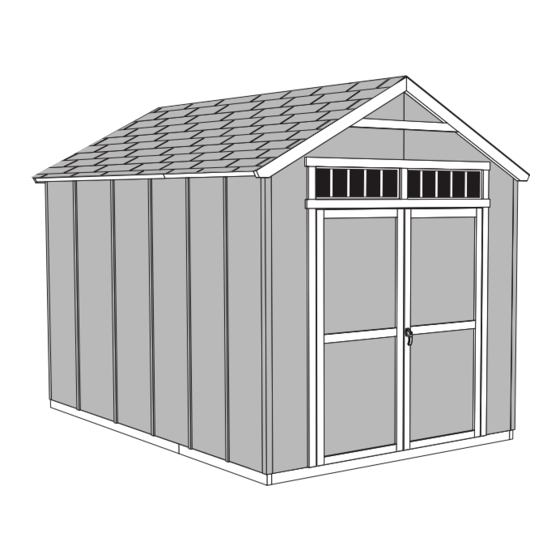
16767-NN 11/27/2012 ASSEMBLY MANUAL A Backyard Products Company MAJESTIC 8' x 12' (244 x 366 cm) ACTUAL FLOOR SIZE IS 96 x 144" (244 x 366 cm) KEEP THIS MANUAL FOR FUTURE REFERENCE IMPORTANT! READ INSTRUCTIONS THOROUGHLY PRIOR TO BEGINNING ASSEMBLY. - Page 4 TOOLS Required Optional ❑ ❑ ❑ Phillips Tool Belt/ Utility Knife Screwdriver Nail Pouch ❑ Shingle Blades ❑ Drill / Driver ❑ ❑ 1/4" Drill Bit Tin Snips ❑ Caulk Gun ❑ (for drip edge) 3/8" Drill Bit ❑ 1/2" Drill Bit ❑...
-
Page 5: Additional Materials
ADDITIONAL MATERIALS FOUNDATION OR FLOOR MATERIALS • oor panel sizes and quantities required. • This shed kit does not include ANY leveling materials. • See the FLOOR LEVELING section on page 8 for recommended methods and suggested materials to properly level your c site. -
Page 6: Parts List
PARTS IDENTIFICATION AND SIZES Part identiÀ cation Treated lumber is stamped: WOOD SIZE CONVERSION CHART letters are stamped on some parts. Nominal Board Size Actual Size 2" x 4"....1-1/2" x 3-1/2" (3,8 x 8,9 cm) 1" x 4"....3/4" x 3-1/2" (1,9 x 8,9 cm) 2"... - Page 7 PARTS LIST continued... 2 x 3 x 28-5/8" (5 x 7,6 x 73 cm) 2 x 3 x 96" (5 x 7,6 x 244 cm) 2 x 4 x 96" (5 x 10 x 244 cm) 2 x 3 x 69" (5 x 7,6 x 175,3 cm) PANEL PARTS LIST NOTE: Panel parts are not stamped.
- Page 8 WALL PANEL & DOORS PARTS LIST 3/8 x 48 x 84" LEFT DOOR RIGHT DOOR (1 x 122 x 213 cm) FASTENER/HARDWARE BAG (Shown Actual Size) 1-1/2" (3,8 cm) x110 2" (5,0 cm) 1-1/4" (3,2 cm) 3" (7,6 cm) 2" (5,0 cm) 1-1/4"...
- Page 9 FLOOR PANELS (Not Included) You will need Á oor panels and nails to complete your Á oor. Floor panel sizes and quantities are shown below. NOTE: Use a minimum of 5/8" (1,6 cm) oriented strand board (OSB). 5/8 x 48 x 96" (1,6 x 122 x 244 cm) 1 lb.
- Page 10 FLOOR LEVELING OPTIONS There are multiple ways to level your Û oor frame. Our recommended leveling method is shown below. Leveling materials are not included in this kit. PREFERRED METHOD - 4x4 TREATED RUNNERS • 3" Screws angled into 4x4. •...
- Page 11 CONCRETE FOUNDATION Your kit contains all materials to construct a wooden Û oor. If you choose to install your kit on a concrete slab refer to the diagram below. Treated Sill Plate Caulk between sill plate and concrete. 3-1/2" (8,9 cm) 4"...
-
Page 12: Parts Required
FLOOR FRAME PARTS REQUIRED: 3" (7,6 cm) x32 2 x 4 x 96" (5 x 10 x 244 cm) Look for 2 x 4 x 93" (5 x 10 x 236 cm) TREATED Stamp 2 x 4 x 48" (5 x 10 x 122 cm) BEGIN Orient parts as shown on Á... - Page 13 LEVEL AND SQUARE FLOOR FRAME Before attaching Û oor decking, it is important to level and square the Û oor frame. A level and square Û oor frame is required to correctly construct your shed. BEGIN See page 8 for the preferred Á oor leveling method. Use level and check the frame is level before applying Á...
- Page 14 FLOOR PANELS PARTS REQUIRED: FLOOR PANELS NOT INCLUDED. SEE PAGE 7 FOR PANEL SIZES 2" (5 cm) x55 AND QUANTITIES. 5/8 x 48 x 96" (1,6 x 122 x 244 cm) Ensure your Á oor frame is square by installing one panel and squaring frame.
- Page 15 FLOOR PANELS PARTS REQUIRED: 2" (5 cm) x110 5/8 x 48 x 96" (1,6 x 122 x 244 cm) Continue installing panels with rough side up (painted grid lines). Use grid lines on panel for 2" nails 6" apart on edges, and 12"...
- Page 16 IMPORTANT! Check the Á oor frame is level after installing Á oor panels. Re-level if needed. • The Á oor should used as a stable work surface for wall construction. • Organize your assembly procedure during the build process HINT: to avoid over-handling of the walls.
- Page 17 SIDE WALL FRAMES PARTS REQUIRED: 2 x 3 x 48" (5 x 7,6 x 122 cm) 3" (7,6 cm) x64 2 x 3 x 78-1/2" (5 x 7,6 x 199 cm) 2 x 3 x 96" (5 x 7,6 x 244 cm) BEGIN Orient parts on edge on Á...
- Page 18 SIDE WALL PANELS PARTS REQUIRED: 2" (5 cm) x45 48 x 84" 122 x 213 cm) 3/4" GAUGE BLOCK SPACER 2 x 3 x 13" (5 x 7,6 x 33 cm) as Ensure your wall frame is square by installing one panel and squaring frame.
- Page 19 SIDE WALL PANELS PARTS REQUIRED: 2" (5 cm) x90 48 x 84" 3/4" GAUGE 122 x 213 cm) BLOCK 2 x 3 x 13" (5 x 7,6 x 33 cm) as SPACER Place center 48" panel on frame as For squareness maintain shown with primed side facing up.
- Page 20 BACK WALL PARTS REQUIRED: 48 x 96" (122 x 244 cm) 1-1/2" (3,8 cm) x11 2 x 3 x 13" (5 x 7,6 x 33 cm) 2 x 3 x 35-1/4" (5 x 7,6 x 89,5 cm) 2 x 3 x 91" (5 x 7,6 x 231 cm) BEGIN Orient parts on Á...
- Page 21 BACK WALL PARTS REQUIRED: TEMPORARY SUPPORT 5/8 x 3 x 9" (1,6 x 7,6 x 23 cm) 1-1/2" (3,8 cm) x15 2 x 3 x 35-1/4" (5 x 7,6 x 89,5 cm) 2 x 3 x 31" (5 x 7,6 x 79 cm) 2 x 3 x 91"...
- Page 22 BACK WALL PARTS REQUIRED: 1-1/2" (3,8 cm) x26 2 x 3 x 13" (5 x 7,6 x 33 cm) 48 x 96" (122 x 244 cm) Place right panel onto frame primed side up. Nail using 1-1/2" nails 6" (15 cm) apart on edges, and 12"...
- Page 23 BACK WALL PARTS REQUIRED: 1-1/2" (3,8 cm) x12 3/8 x 12 x 24" (1 x 30,5 x 61 cm) 2 x 3 x 13" (5 x 7,6 x 33 cm) 3/8 x 12 x 24" (1 x 30,5 x 61 cm) Nail left and right 12 x 24"...
- Page 24 FRONT WALL FRAME PARTS REQUIRED: 2" (5 cm) x6 2 x 4 x 64" (5 x 10 x 162,5 cm) 2 x 3 x 9" (5 x 7,6 x 23 cm) 1 x 3 x 12" (2,5 x 7,6 x 30,5 cm) BEGIN Orient NA and UX on Á...
- Page 25 FRONT WALL FRAME PARTS REQUIRED: 3" (7,6 cm) x8 2 x 3 x 82-1/2" (5 x 7,6 x 210 cm) Temporary 2 x 3 x 84" (5 x 7,6 x 213 cm) Support Pre-Assembled 7/16 x 25-3/4 x 48" (1,1 x 65,4 x 122 cm) BEGIN Orient parts on edge on Á...
- Page 26 FRONT WALL FRAME Temporary PARTS REQUIRED: Support 3" (7,6 cm) x2 2 x 3 x 23" (5 x 7,6 x 58 cm) 3" (7,6 cm) x2 7/16 x 25-3/4 x 48" (1,1 x 65,4 x 122 cm) Secure NA with (2) 3" nails (Fig. A) . Place two roof panels as temporary supports above frame.
- Page 27 FRONT WALL PANELS PARTS REQUIRED: 1-1/2" (3,8 cm) x24 Handle panels with care to avoid breakage. BEGIN Place left panel on front wall frame with primed side up as shown. Hold the 1-1/4" and 1/4" measurement. 1-1/4" (3,2 cm) Nail with 1-1/2" nails 6" (15 cm) apart. Maintain 64" (162,5 cm) measurement between studs and square frame.
- Page 28 FRONT WALL PANELS PARTS REQUIRED: 1-1/2" (3,8 cm) x30 12 x 24" (30,5 x 61 cm) 12 x 24" (30,5 x 61 cm) Place right panel on front wall frame with primed side up as shown. Nail with 1-1/2" nails 6" (15 cm) apart. Maintain 64"...
-
Page 29: Back Wall Installation
BACK WALL INSTALLATION PARTS REQUIRED (TEMPORARY): 3" (7,6 cm) x6 2 x 3 x 96" (5 x 7,6 x 244 cm) 3" (7,6 cm) x4 2" (5 cm) x18 BEGIN Center back wall assembly on the 96" (244 cm) Á oor dimension. Use PT as a temporary brace. - Page 30 SIDE WALLS INSTALLATION 3" (7,6 cm) x24 3" (7,6 cm) x4 2" (5 cm) x39 BEGIN Stand right sidewall on Á oor. It is important to secure the sidewall in the following order. Center sidewall on Á oor front to back. Nail the lower backwall corner to the sidewall frame with one 2"...
- Page 31 FRONT WALL INSTALLATION 3" (7,6 cm) x2 3" (7,6 cm) x4 2" (5 cm) x30 BEGIN Stand frontwall on Á oor. It is important to secure the frontwall in the following order. Center frontwall on Á oor side-to-side. Nail the frontwall Á ush to the Á oor using 2"...
- Page 32 LOFT FRAME PARTS REQUIRED: 3" (7,6 cm) x8 2 x 4 x 96" (5 x 10 x 244 cm) BEGIN Measure the top of back wall loft support to Á oor. Measure and mark the same measurement on the back side of sidewall studs at each side as shown. Install one TP level against back side of studs at mark with two 3"...
- Page 33 SHELF FRAME PARTS REQUIRED: 3" (7,6 cm) x4 3" (7,6 cm) x8 2 x 3 x 96" (5 x 7,6 x 244 cm) BEGIN Place PT Á ush to top of loft support as shown (Fig A) . Install PT level against studs and with top edge of loft support. Secure PT with two 3"...
- Page 34 SHELF FRAME PARTS REQUIRED: 3" (7,6 cm) x8 2 x 3 x 96" (5 x 7,6 x 244 cm) Assistance may be required to install PT. Place PT against loft support (Fig. A) and secure Á ush using two 3" screws. Check PT for level and secure at front wall with two 3"...
- Page 35 WORKBENCH PARTS REQUIRED: 3" (7,6 cm) x4 2 x 3 x 96" (5 x 7,6 x 244 cm) BEGIN Measure the top of back wall workbench support from Á oor. Measure and mark the same measurement on the back side of sidewall studs at each side as shown. Install PT level against back side of studs at mark with two 3"...
- Page 36 WORKBENCH PARTS REQUIRED: 3" (7,6 cm) x4 2 x 3 x 28-5/8" (5 x 7,6 x 73 cm) 2" (5 cm) x20 7/16 x 23-7/8 x 91" (1,1 x 61 x 231 cm) Place workbench into gap in back wall upright. Secure with 2"...
- Page 37 LOFT PANELS 7/16 x 44-1/4 x 48" PARTS REQUIRED: (1,1 x 112 x 122 cm) 2" (5 cm) x8 BEGIN Place loft panels onto the three loft supports centered from side-to-side and Á ush with the back wall panel. Fit panels into gap. IMPORTANT! Use only FOUR 2"...
- Page 38 SHELF PANELS PARTS REQUIRED: 2" (5 cm) x40 7/16 x 11-7/8 x 96" (1,1 x 30 x 244 cm) BEGIN Place shelf panel onto the left wall shelf frame. Shelf panel should be Á ush against shelf support and loft panel. Attach using 2" nails, as shown. Repeat on opposite side.
- Page 39 RAFTERS PARTS REQUIRED: 2" (5 cm) x120 6 x 24" (15 x 61 cm) 2 x 4 x 55-3/16" (5 x 10 x 140 cm) ¸ BEGIN You will build FIVE assemblies; Place two rafter-halves in the corner of back and side walls. Rafters should touch at peak.
-
Page 40: End View
RAFTERS PARTS REQUIRED: 3" (7,6 cm) x 20 2" (5 cm) x 10 Preassembled ¸ BEGIN Locate rafters directly over studs and Á ush to wall panel. Check that you have the measurements shown. First, secure ends of rafters with one 2" screw at each end (Fig. A) . Secure ends of rafters with two 3"... - Page 41 TRIM PARTS REQUIRED: 1-1/4" (3,2 cm) x64 2 x 2 x 84" (5 x 5 x 213 cm) BEGIN Install metal corner trim Á ush with top of side panel (Fig. A) . Secure trim to wall using sixteen 1-1/4" nails (eight per side) spaced evenly as shown.
- Page 42 GABLE TRIM PARTS REQUIRED: 2 x 4 x 59-1/8" (5 x 10 x 150,2 cm) Temporary Straight Edge 2 x 3 x 69" (5 x 7,6 x 175,3 cm) BEGIN Orient AG on fl oor as shown. Using OO as a straight edge, mark a line 1-1/4"...
- Page 43 GABLE TRIM PARTS REQUIRED: 1-1/4" (3,2 cm) 2 x 4 x 59-1/8" (5 x 10 x 150 cm) Position one AG 1-1/4" up from front panel edge and center with panel seam (Fig. A) . Attach trim with seven 1-1/4" screws from inside. Install two screws at seam (Fig.
- Page 44 GABLE TRIM PARTS REQUIRED: 1-1/4" (3,2 cm) x24 2 x 3 x 41-7/8" (5 x 7,6 x 106 cm) BEGIN Install AW level over seam of front wall panels with twelve 1-1/4" screws from inside as shown. Repeat step 1 installing AW over seam at back side. FINISH You have À...
-
Page 45: Gauge Block
ROOF PANELS PARTS REQUIRED: 2" (5 cm) x4 7/16 x 11-1/4 x 96" 3/4" (1,1 x 28,6 x 244 cm) GAUGE BLOCK 7/16 x 48 x 96" (1,1 x 122 x 244 cm) 7/16 x 11-1/4 x 25-3/4" 7/16 x 25-3/4 x 48" (1,1 x 29 x 65,4 cm) (1,1 x 65,4 x 122 cm) Roof panels may cause serious injury... - Page 46 ROOF PANELS PARTS REQUIRED: 2" (5 cm) x174 3/4" GAUGE BLOCK Keep spacing between the center of the rafters at the lower edge of the panel and secure with one 2" nail into each rafter (Fig. E). Move to the top of the panel and keep spacing between the center of the rafters.
- Page 47 COLLAR TIES PARTS REQUIRED: 2" (5 cm) x18 1 x 4 x 60" (2,5 x 10 x 152 cm) BEGIN Position and level each JF on À rst three rafters past door opening. Do not install JF over loft. HINT: For best appearance install JF on rafter facing away from door opening. Glue JF and attach with 2"...
- Page 48 LOFT PANELS 2" (5 cm) x22 BEGIN Continue nailing 2" nails in each loft panel as shown. FINISH You have À nished your loft panels. Attention: Load not to exceed 250 lbs evenly distributed across loft.
- Page 49 SOFFIT TRIM PARTS REQUIRED: 3" (7,6 cm) x 8 1-1/4" (3,2 cm) x40 2 x 4 x 48-3/4" (5 x 10 x 124 cm) 2 x 4 x 96" (5 x 10 x 244 cm) ¸ BEGIN Attach sofÀ t trim Á ush to sidewall panels and under roof panels (Fig. A) using 1-1/4"...
- Page 50 BATTENS PARTS REQUIRED: 2" (5 cm) x40 3/8 x 1-3/4 x 82-1/4" (0,9 x 4,4 x 209 cm) ¸ BEGIN Install top of battens positioned against TP and AN on side wall panels (Fig. A) using 2" nails as shown. Evenly space battens 24" apart covering any seams on panels.
- Page 51 DOORS PARTS REQUIRED: 1 x 3 x 5" (2,5 x 7,6 x 12,7 cm) 1-1/4" (3,2 cm) x2 2 x 3 x 69" (5 x 7,6 x 175,3 cm) 3" (7,6 cm) x4 HINT: Look for 3/8" SPACER attached to doors. Left Door Right Door BEGIN...
- Page 52 DOORS PARTS REQUIRED: 3" (7,6 cm) x13 2 x 3 x 69" (5 x 7,6 x 175,3 cm) Attach temporary support OO as a ledger board Á ush under wall panels for doors to rest on, using three 3" screws (Fig. A) . Flush against wall panels.
-
Page 53: Right Door
DOOR PARTS REQUIRED: 3/4" (1,9 cm) x38 BEGIN Reinforce the door trim using 3/4" screws through door panel into trim (Fig. A) . Locate screws as shown in Fig. B . Use two screws at seams. FINISH You have À nished reinforcing your doors. Door Panel Install 3/4"... - Page 54 WINDOWS PARTS REQUIRED: 1-1/4" (3,2 cm) x4 10-1/2 x 32-1/2" (27 x 82,5 cm) ¸ BEGIN Apply high quality exterior-grade caulk to seal window. From outside of shed, position windows in opening and level. Use (2) screws at top of windows. Do not fully tighten screws.
- Page 55 WINDOWS TRIM PARTS REQUIRED: 2" (5 cm) x14 5/8 x 2-1/2 x 72" (1,6 x 6,3 x 183 cm) Center ZJ over doors and secure using fourteen 2" À nish nails into framing as shown. Do not nail into window Á ange. HINT: Mark edge of window frame on ZJ .
- Page 56 WINDOW TRIM PARTS REQUIRED: 2" (5 cm) x14 5/8 x 2-1/2 x 9" (1,6 x6,3 x 23 cm) Install three EY using 2" nails into framing as shown. NOTE: Use marks on ZJ for locating window Á ange. Do not nail into window Á ange. Remove temporary screws after installiing three EY .
- Page 57 WINDOWS PARTS REQUIRED: 2" (5 cm) x14 3/4" (1,9 cm) x10 5/8 x 3 x 72" (1,6 x 7,6 x 183 cm) Install ZJ centered over windows using seven 2" À nish nails into framing. Do not nail into window Á ange . Flush Flush Flush...
- Page 58 DOOR WEATHERSTRIP PARTS REQUIRED: 2" (5 cm) x14 2 x 3 x 69" (5 x 7,6 x 175 cm) BEGIN With left door closed, center a weatherstrip OO vertically on the left door in the door opening (Fig. A ). OO will offset the left door 1" OUT past the door trim 1" (Fig. B). Secure OO using seven 3"...
- Page 59 DOOR PARTS REQUIRED: 3/4" (1,9 cm) x12 BEGIN Mount one barrel bolt Á ush at top of OO on left door using 3/4" screws as shown (Fig A) . Mount the second barrel bolt Á ush at bottom of OO on left door using 3/4" screws as shown (Fig B) .
-
Page 60: Door Hardware
DOOR HARDWARE PARTS REQUIRED: 1-1/4" (3,2 cm) x2 1" (2,5 cm) x2 1/2" (13 mm) Drill Bit 1/4" (6 mm) Drill Bit BEGIN Measure and mark location of hole on outside of right door as shown (Fig. A) . Pre-drill hole with 1/4" drill. Re-drill hole with 1/2"... - Page 61 PAINT & CAULK - NOT INCLUDED - • Use acrylic latex caulk that is paintable. Caulk at all horizontal and vertical seams, between the trim and walls, and all around the door trim. • Use a high quality exterior acrylic latex paint. When painting your building, there are a few key areas that can be easily overlooked that must be painted: •...
- Page 62 SHINGLES - NOT INCLUDED - • Follow directions provided by manufacturer and these instructions. Familiarize yourself with a 3-Tab Shingle. Notch Notch SHINGLE NAIL PATTERN 1/2" 1" Sealing Strip (1,3 cm) 1" (2,5 cm) (2,5 cm) Half A Rain Slot Full Rain Slot NAILS NEVER DRIVE FASTENERS INTO OR ABOVE SEALING STRIPS.
- Page 63 SHINGLES continued... Beginning at front of shed, install À rst row of shingles with notch at 1" past roof edge or Á ush with drip edge. Roof Deck FRONT OF BACK OF SHED SHED 1" (2,5 cm) Flush with starter row. Notch - or - Drip Edge...
- Page 64 SHINGLES continued... Continue installing rows of shingles to the peak. At the peak make sure there is a maximum of 5" or less to the rain slot, as shown below. If shingles overlap at ridge cut to peak with a utility knife. 5"...
- Page 65 SHINGLES - RIDGE CAP • You will À nish off the top of the roof with a ridge cap made from shingles. BEGIN Cut shingles into THREE pieces. Hint: Use cut-off pieces À rst. 2" 2" (5 cm) (5 cm 2"...
- Page 66 SHINGLES - RIDGE CAP continued... Continue installing ridge cap to back of roof. Make sure there is 4" between the shingle-color and edge of shingles. 4" (10 cm) Trim cap off Á ush to shingles When you have 4" minimum of shingle color cut one piece to cap your roof. Cut at top of rain slot.
-
Page 67: Warranty
WARRANTY Backyard Storage Solutions, LLC warrants the following: Limited Conditional Every product is warranted from defects in workmanship and manufacturing for one year. Warranty * All hardware and metal components are warranted for two years. Trim is warranted for 10 years. Waferboard siding and sheathing is warranted for two years.