Table of Contents
Advertisement
Quick Links
Advertisement
Table of Contents

Subscribe to Our Youtube Channel
Related Manuals for Spartus ProMIG 535DP


Summary of Contents for Spartus ProMIG 535DP
- Page 1 SPARTUS® ProMIG 535DP User’s manual...
- Page 2 Therefore, our offer covers such a wide assortment of products. Thank you very much for your trust in our company. We would like to invite you to familiarize yourself with the remaining products and offer at www.spartus. info or directly at a local distributor of SPARTUS® products.
-
Page 3: Table Of Contents
TABLE OF CONTENTS 1. SAFE USE – HAZARDS ASSOCIATED WITH ARC WELDING AND PLASMA CUTTING ....2 1.1 General safety rules ................................2 1.2 Electric shock can kill ................................2 1.3 Welding arc radiation can be dangerous ........................3 1.4 Vapours and gases can be dangerous .......................... 3 1.5 Noise can be harmful ................................ -
Page 4: Safe Use - Hazards Associated With Arc Welding And Plasma Cutting
USER’S MANUAL 1. SAFE USE – HAZARDS ASSOCIATED WITH ARC WELDING AND PLASMA CUTTING Arc welding and plasma cutting are processes feeder fitted with spool and harness). Care that can pose hazards for the operator and per- shall be taken during manual handling. sons in his vicinity. -
Page 5: Welding Arc Radiation Can Be Dangerous
USER’S MANUAL • Power supply must never be connected Such radiation can be direct or reflected from before the accessories of SK sockets/con- surfaces such as bright metals and light colo- nectors are properly installed in the device. ured objects. •... -
Page 6: Noise Can Be Harmful
USER’S MANUAL Arc welding and allied processes produce wel- in case of an emergency, are in the imme- ding fume which may pollute the atmosphere diate vicinity. surrounding the work. Welding fume is a vary- • In closed rooms or in certain circumstances ing mixture of airborne gases and fine particles during outdoor operations, it may be re- which, if inhaled or swallowed, constitute a... -
Page 7: Fire Or Explosion Hazard
USER’S MANUAL source, observed for an adequate period after its c) effective maintenance of sound protection termination. devices, • „Hot spots” and immediate surroundings d) indication as „ear protection areas” where should be observed until their temperature applicable, has dropped to normal. e) restriction of entry to these „ear protection 1.6.2 Explosion hazard areas”... -
Page 8: Other Hazards
USER’S MANUAL 1.7.4 Moving elements can be dangerous cylinder valve socket when the valve is being opened. • Special valve shield should always be in- stalled during cylinder transportation or when the cylinder is not used. OTHER HAZARDS Arc welding and allied processes carrying other All protective elements and device housing hazards not listed before. -
Page 9: Symbols Used In Instructions
USER’S MANUAL WARNING The maximum voltage of 15kV. Accidental pressing of the microswitch results in unintentional arc ignition. Never bring a bare hand close to the electrode, when the device is connected to a power source. 1.9 SYMBOLS USED IN INSTRUCTIONS We use this symbol to pay your attention about important information. -
Page 10: Assesment Of Area
Methods of reducing electromagnetic interference are listed in detail in the standard EN 60974-9 – „Arc welding equipment – Part 9: Installation and use”. 4. CONFORMITY WITH STANDARDS SPARTUS® ProMIG 535DP is in conformity with the relevant Union harmonization legislation: LVD 2014/35/UE Low Voltage Directive... -
Page 11: General Description
The device offers a wide range of possibilities for the above-mentioned methods of joining metals. MIG welding ProMIG 535DP is equipped with a synergistic system for MIG / MAG welding with the possibility of selecting the following programs: for mill steel, stainless steel, aluminum welding and braze welding. -
Page 12: Technical Specifications
However it is not designed to be used outdoor during precipitation if it is not covered. 6.2 TECHNICAL PARAMETERS OF DEVICE ProMIG 535DP Input ~3 × 400V ± 10% 50 / 60 Hz Welding current MIG [A] 10 –... -
Page 13: Installation And Use
Dimensions [mm] 1150 x 590 x 1430 7. INSTALLATION AND USE WARNING! SPARTUS® ProMIG 535DP machines are intended for professional and industrial applications. Installation and use of the device may only be carried out appropriately trained professionals. It is forbidden to grinding and/or carrying out other locksmith works or mechanical working of metal in the vicinity of the ventilation opening of unit. -
Page 14: Proper Cooling
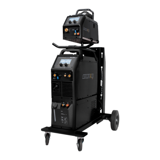
USER’S MANUAL 7.1 PROPER COOLING The unit should be placed stable on a dry and flat surface. Avoid too much slope and slippery surfaces. Check regularly that the vents (inlet, outlet) are not covered. The minimum distance between the welder vents and walls should be 50cm. 7.2 MOVEMENT AND HANDLING The source is available on a specially constructed welding cart (platform), equipped with road wheels and a transport handle. - Page 15 USER’S MANUAL 7.3.1 Welding source Connection cable set – current socket Control panel SK „+” SK „-” socket Gas inlet SK „+” socket Connection cable set – control socket Connection for TIG torch Power cable Toggle switch ON/OFF Remote connection plug: cooler TIG torch gas connector 7.3.2 Cooler Water inlet...
- Page 16 USER’S MANUAL 7.3.3 Wire feeder EURO socket Wire feeder control anode Spool Gun socket Positive output anode Water outlet Water inlet Backwater inlet Backwater outlet Gas connector Wire reel shaft Wire feeder inlet guide Wire feed tension adjustment Wire drive rollers Wire feed tension arms...
-
Page 17: Connecting To Power Supply
USER’S MANUAL 7.4 CONNECTING TO POWER SUPPLY Requirements for power network parameters (voltage, permissible range of mains voltage fluctuations etc.) are given in the table with technical parameters of device and on the rating plate of welding machine. Before connecting the unit to the power source: •... - Page 18 USER’S MANUAL 7.5.1 Connecting the gas cylinder 1. The cylinder with appropriate shielding gas, should be placed in a vertical position and se- cured against falling over in accordance with safety requirements (for gas cylinders under the influence). 2. Make sure that the valve cylinder is closed. 3.
- Page 19 USER’S MANUAL 7.5.5 Device installation – MIG/MAG welding Before connecting hardware and shielding gas to the device, make sure that the device is discon- nected from power source and switch is in the OFF position. For most applications during MIG/MAG welding the polarity of the welding should be positive ‚+’ on the EURO socket and negative „-”...
- Page 20 USER’S MANUAL 3. Plug the Spool Gun into the euro connect socket 7 on the front panel and tighten. IMPORTANT: When connecting the torch be sure to tighten the adaptor nut completely tight. A loose connection can result in arcing between the gun and machine connector and that causes serious damage to both the torch and machine connections.
-
Page 21: Installation - Mma Welding
USER’S MANUAL 11. Pull the trigger to drive the wire down the neck until it exits the contact tip. 12. Carefully open the gas cylinder valve and set the required gas flow rate. 13. Set welding parameters using the knobs as shown on digital displays. INSTALLATION –... -
Page 22: Installation - Tig Welding
USER’S MANUAL 7.7 INSTALLATION – TIG WELDING Before connecting hardware and shielding gas to the device, make sure that the device is discon- nected from power source and switch is in the OFF position. 7.7.1 Connecting the gas cylinder 1. The cylinder with appropriate shielding gas, should stand upright and be secured against tipping over in accordance with safety requirements. -
Page 23: Device Control Panel - Using
USER’S MANUAL 7.8 DEVICE CONTROL PANEL – USING promig 535 dp mode parm cooling 1s save feed Welding mode button Welding adjustment knob 2 Button for inserting the welding Welding adjustment knob 1 wire into the MIG gun 2021-03-26 Gas test button Save/recall JOB program button Function button Cooling mode button: gas/liquid... - Page 24 USER’S MANUAL MMA DISPLAY INTRODUCTION promig 535 dp mode parm cooling 1s save feed A MMA WELDING MODE BUTTON H WELDING ADJUSTMENT KNOB 1: welding current I WELDING ADJUSTMENT KNOB 2: Hot Start or Arc Force 2021-03-26 TIG LIFT DISPLAY INTRODUCTION promig 535 dp mode parm...
- Page 25 USER’S MANUAL A TIG Lift WELDING MODE BUTTON B WELDING ADJUSTMENT KNOB 1: welding current D FUNCTION BUTTON: press it to enter the function interface E COOLING MODE BUTTON: press to select water cooling F WELDING ADJUSTMENT KNOB 2: Down Slope FUNCTION INTERFACE –...
- Page 26 USER’S MANUAL Press the gun switch and hold it. Electromagnetic gas valve is turned on. The shielding gas stars to flow. Pre-gas time. Initiation of the welding arc. Arc is ignited and the output current rises to the setting welding current from the min.
- Page 27 USER’S MANUAL MIG MANUAL DISPLAY INTRODUCTION 8.105RM.329-A wire feeder 4r cooling mode parm 1s save feed A MIG Manual WELDING MODE BUTTON B WELDING ADJUSTMENT KNOB 1: wire feeding speed 2020-03-26 C GAS TEST BUTTON D FUNCTION BUTTON: press it to enter the function interface E COOLING MODE BUTTON: press to select water cooling F WELDING ADJUSTMENT KNOB 2: voltage / inductance G BUTTON FOR INSERTING THE WELDING WIRE INTO THE MIG GUN...
- Page 28 USER’S MANUAL PANEL FUNCTIONS & DESCRIPTIONS Slow feed 1. Trigger mode: 2T/4T / SPOT 2. Pre Gaz: 0~5s This function is used to regulate the speed of wire feeding increasing. Range 3. Post Gaz: 0~10s 4. Burnback: 0~10 5. Slow Feed: 0~5s Spool gun: ON/OFF Spot Weld trigger mode: Spot weld...
- Page 29 USER’S MANUAL A MIG Dual Pulse WELDING MODE BUTTON B WELDING ADJUSTMENT KNOB 1: current / wire feeding speed C GAS TEST BUTTON D FUNCTION BUTTON: press it to enter the function interface E COOLING MODE BUTTON: press to select water cooling F WELDING ADJUSTMENT KNOB 2: arc length adjustment / inductance G BUTTON FOR INSERTING THE WELDING WIRE INTO THE MIG GUN FUNCTION INTERFACE –...
- Page 30 USER’S MANUAL 1. Trigger mode: 2T/4T / s4T(4T+) (SPOT for MIG Pulse) 2. Wire material: Fe-metal solid-cored / Fe-metal flux-cored / SS-metal solid-cored / CuSi / Al-Mg solid-cored / Al-Si solid-cored / Al 99.5 solid-cored / SS-metal flux-cored / CuAl 3.
- Page 31 USER’S MANUAL A MIG SYN WELDING MODE BUTTON B WELDING ADJUSTMENT KNOB 1: current / wire feeding speed C GAS TEST BUTTON D FUNCTION BUTTON: press it to enter the function interface E COOLING MODE BUTTON: press to select water cooling F WELDING ADJUSTMENT KNOB 2: voltage / voltage correction G BUTTON FOR INSERTING THE WELDING WIRE INTO THE MIG GUN FUNCTION INTERFACE –...
- Page 32 USER’S MANUAL Synergy programs MIG SYNERGY WELDING WIRE WIRE DIAMETER (mm) SHIELDING GAS Fe-metal solid cored 0.8 - 1.6 80%Ar + 20%CO ; 100%CO Fe-metal Flux cored 1.2 - 1.6 100%CO Ss-metal solid cored 1.0 - 1.6 98%Ar + 2%CO Ss-metal Flux cored 100%CO CuSi...
-
Page 33: Remote Control
USER’S MANUAL J1 PARAMETERS DISPLAY: set the parameters of the selected program B WELDING ADJUSTMENT KNOB 1: delete the parameters H JOB BUTTON: press it for 3s to enter JOB programs and press it for 1s to save parameters. J2 JOB NUMBER DISPLAY F WELDING ADJUSTMENT KNOB 2: load the selected JOB program number Save / activate / delete memory channels on the device The device has 10 memory channels on which you can save the most-used machine settings. -
Page 34: Welding Trolley Assembly
USER’S MANUAL 8. WELDING TROLLEY ASSEMBLY Gas tank support 12. Fixed plate of wire feeder (up) – 2 pcs Bottom plate 13. Fixed plate of wire feeder (down) – 2 pcs Fixed plate 14. Screw M5*10 – 4 pcs Universal wheel ф125mm 15. - Page 35 USER’S MANUAL...
-
Page 36: Maintenance
11. TROUBLESHOOTING Not all problems with functioning of the device, are the evidence of failure. You can independently carry out an analysis in search of probable failure. In case of doubt, please contact to SPARTUS® dealer or authorized service center. - Page 37 USER’S MANUAL PROBLEMS WITH THE DEVICE Turn ON power but the LCD Switch, fuse or power cord damaged. display is not illuminated. Fan damaged. After welding machine is over-heat, the fan doesn’t work. The cable is loose. No gas in the gas cylinder. Press the gun microswitch, Electromagnetic valve, control switch or control no output shielded gas.
- Page 38 USER’S MANUAL Liner worn or clogged. Wire misaligned in drive roller groove. Incorrect drive roller size or wrong type of drive roller selected. Interrupted wire feed. Worn drive rollers. Drive roller pressure too high. Wire crossed over on the spool or tangled. Contaminated MIG wire.
- Page 39 A masterly combination of high quality production, excellent parameters and ergonomics – these are fea- tures of the SPARTUS® Master series of devices, which were created with demanding welding jobs in mind. Precision, functionality, excellent parameters and resistance to high workloads –...
- Page 40 Videopresentation of products Subscribe to the channel SPARTUS.INFO...
Need help?
Do you have a question about the ProMIG 535DP and is the answer not in the manual?
Questions and answers