Table of Contents
Advertisement
Quick Links
Advertisement
Table of Contents

Related Manuals for Spartus ProMIG 335DP


Summary of Contents for Spartus ProMIG 335DP
- Page 1 SPARTUS® ProMIG 335DP User’s manual...
- Page 2 Therefore, our offer covers such a wide assortment of products. Thank you very much for your trust in our company. We would like to invite you to familiarize yourself with the remaining products and offer at www.spartus. info or directly at a local distributor of SPARTUS® products.
-
Page 3: Table Of Contents
TABLE OF CONTENTS 1. SAFE USE – HAZARDS ASSOCIATED WITH ARC WELDING AND PLASMA CUTTING ....2 1.1 General safety rules ................................2 1.2 Electric shock can kill ................................2 1.3 Welding arc radiation can be dangerous ........................3 1.4 Vapours and gases can be dangerous .......................... 3 1.5 Noise can be harmful ................................ -
Page 4: Safe Use - Hazards Associated With Arc Welding And Plasma Cutting
USER’S MANUAL 1. SAFE USE – HAZARDS ASSOCIATED WITH ARC WELDING AND PLASMA CUTTING Arc welding and plasma cutting are processes feeder fitted with spool and harness). Care that can pose hazards for the operator and per- shall be taken during manual handling. sons in his vicinity. -
Page 5: Welding Arc Radiation Can Be Dangerous
USER’S MANUAL • Power supply must never be connected Such radiation can be direct or reflected from before the accessories of SK sockets/con- surfaces such as bright metals and light colo- nectors are properly installed in the device. ured objects. •... -
Page 6: Noise Can Be Harmful
USER’S MANUAL Arc welding and allied processes produce wel- in case of an emergency, are in the imme- ding fume which may pollute the atmosphere diate vicinity. surrounding the work. Welding fume is a vary- • In closed rooms or in certain circumstances ing mixture of airborne gases and fine particles during outdoor operations, it may be re- which, if inhaled or swallowed, constitute a... -
Page 7: Fire Or Explosion Hazard
USER’S MANUAL source, observed for an adequate period after its c) effective maintenance of sound protection termination. devices, • „Hot spots” and immediate surroundings d) indication as „ear protection areas” where should be observed until their temperature applicable, has dropped to normal. e) restriction of entry to these „ear protection 1.6.2 Explosion hazard areas”... -
Page 8: Other Hazards
USER’S MANUAL 1.7.4 Moving elements can be dangerous cylinder valve socket when the valve is being opened. • Special valve shield should always be in- stalled during cylinder transportation or when the cylinder is not used. OTHER HAZARDS Arc welding and allied processes carrying other All protective elements and device housing hazards not listed before. -
Page 9: Symbols Used In Instructions
USER’S MANUAL WARNING The maximum voltage of 15kV. Accidental pressing of the microswitch results in unintentional arc ignition. Never bring a bare hand close to the electrode, when the device is connected to a power source. 1.9 SYMBOLS USED IN INSTRUCTIONS We use this symbol to pay your attention about important information. -
Page 10: Assesment Of Area
Methods of reducing electromagnetic interference are listed in detail in the standard EN 60974-9 – „Arc welding equipment – Part 9: Installation and use”. 4. CONFORMITY WITH STANDARDS SPARTUS® ProMIG 335DP is in conformity with the relevant Union harmonization legislation: LVD 2014/35/UE Low Voltage Directive... -
Page 11: General Description
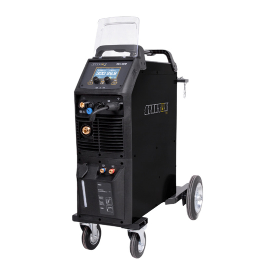
Modern design, bright and legible LCD function panel combined with high-class components makes the SPARTUS® ProMIG 335DP one of the best machines in its class on the market. SPARTUS® Pro line professional devices thanks to its quality, warranty and technical support are... -
Page 12: Purpose Of Use
USER’S MANUAL 5.1 PURPOSE OF USE SPARTUS® ProMIG 335DP welding devices are designed for: • Metal Inert Gas welding (MIG) or Metal Active Gas welding (MAG), • Tungsten Inert Gas welding (TIG), • Manual Metal Arc welding (MMA). 6. TECHNICAL SPECIFICATIONS 6.1 OPERATION, STORAGE AND TRANSPORT... - Page 13 USER’S MANUAL MIG PARAMETERS Wire feeder built-in, 4-roll Wire diameter Ø [mm] 0.8 / 1.0 / 1.2 Welding wire spool ≤ 15[kg], ø200/300 Wire feeding speed [m/min] 2 – 24 Wire feeding test 2T / 4T control Welding with pulsation 1P and 2P ...
-
Page 14: Installation And Use
USER’S MANUAL 7. INSTALLATION AND USE WARNING! SPARTUS® ProMIG 335DP machines are intended for professional and industrial applications. Installation and use of the device may only be carried out appropriately trained professionals. It is forbidden to grinding and/or carrying out other locksmith works or mechanical working of metal in the vicinity of the ventilation opening of unit. - Page 15 USER’S MANUAL 7.3.1 Welding source Control panel SK „+” socket SK „-” socket MIG torch EURO connector TIG remote connection plug Gas inlet MIG torch polarity change power Power cable connection Toggle switch ON/OFF TIG torch gas connector 7.3.2 Cooler Water inlet Water outlet for TIG Backwater inlet for TIG...
-
Page 16: Connecting To Power Supply
USER’S MANUAL 7.3.3 Wire feeder Spool holder Wire feeder inlet guide Wire feed tension adjustment Wire feeder rollers Wire feed tension arms 7.4 CONNECTING TO POWER SUPPLY Requirements for power network parameters (voltage, permissible range of mains voltage fluctuations etc.) are given in the table with technical parameters of device and on the rating plate of welding machine. -
Page 17: Installation - Mig/Mag Welding
USER’S MANUAL 7.4.1 Scheme of connection of power plug connector 400V L1, L2, L3 Phase conductors Protective conductor Neutral conductor WARNING! It is forbidden bridging PE and N cables. it may cause serious risk of electric shock! In some cases, colours of power cords may vary from those shown on diagram. For example when the device has a four-wired three phase power cord. - Page 18 USER’S MANUAL 4. Pass end of wire through wire inlet guide 18 , through groove of drive roll and EURO socket guide. The end of welding wire should leave a distance approx. 10mm beyond outline of EURO socket 7 . 5.
- Page 19 USER’S MANUAL Pressure regulator Power cable Gas hose Gas cylinder Work cable Cooler Welded material MIG/MAG gun Control cable 7.5.6 Installation & operation for SPOOL GUN 1. Insert the earth cable plug into the SK „-” socket 2 on the front of the machine and twist to tighten.
-
Page 20: Installation - Mma Welding
USER’S MANUAL 9. Place a spool of wire inside the spool holder on post. 10. Feed the wire through the drive rolls and into the inlet guide tube. Tighten the wire tension swing arm. 11. Pull the trigger to drive the wire down the neck until it exits the contact tip. 12. -
Page 21: Installation - Tig Welding
USER’S MANUAL 4. Connect the welder into power supply in accordance with appropriate guidelines (see 7.5). 5. Turn on the welder by setting power switch 10 in the ON position. 6. The device is ready to weld. Work cable Welded material Electrode holder Control cable 7.7 INSTALLATION –... -
Page 22: Device Control Panel - Using
USER’S MANUAL Pressure regulator Gas hose Power cable Gas cylinder Welded material Control cable Work cable TIG torch 7.8 DEVICE CONTROL PANEL – USING promig 335 DP mode parm cooling 1s save feed Welding mode button Welding adjustment knob 2 Button for inserting the welding Welding adjustment knob 1 wire into the MIG gun... - Page 23 USER’S MANUAL 7.8.1 Detailed description of selected buttons on the panel A WELDING MODE BUTTON: • MIG Synergic • MIG Pulse • MIG Dual Pulse • MIG Manual • TIG Lift • MMA B WELDING ADJUSTMENT KNOB 1 Press it to select parameters and turn it to adjust values, such as welding current. In function interface, turn it to select parameters.
- Page 24 USER’S MANUAL TIG LIFT DISPLAY INTRODUCTION promig 335 DP mode parm cooling 1s save feed A TIG Lift WELDING MODE BUTTON B WELDING ADJUSTMENT KNOB 1: welding current D FUNCTION BUTTON: press it to enter the function interface E COOLING MODE BUTTON: press to select water cooling F WELDING ADJUSTMENT KNOB 2: Down Slope FUNCTION INTERFACE –...
- Page 25 USER’S MANUAL Course of TIG welding process (2T) During TIG function 2T, you can not set the current parameters of the initial and final current. I (A) welding current I loosing the TIG torch switch the setting base current I arc ignation turning off arc t (s)
- Page 26 USER’S MANUAL pressing the button again I (A) on the TIG torch welding current I loosing the TIG loosing the TIG torch switch torch switch turning off arc arc ignation t (s) press and hold the TIG torch switch Press and hold the gun switch, Electromagnetic gas valve is turned on. The shielding gas starts to flow.
- Page 27 USER’S MANUAL A MIG Manual WELDING MODE BUTTON B WELDING ADJUSTMENT KNOB 1: wire feeding speed C GAS TEST BUTTON D FUNCTION BUTTON: press it to enter the function interface E COOLING MODE BUTTON: press to select water cooling F WELDING ADJUSTMENT KNOB 2: inductance G BUTTON FOR INSERTING THE WELDING WIRE INTO THE MIG GUN FUNCTION INTERFACE –...
- Page 28 Spot Weld trig USER’S MANUAL Spot we SPOT weld trigger mode Gun Switch Gun Switch Gas Supply Gas Supply Wire Feed Output Voltage Wire Feed Output Current SPOT Weld Time Output Voltag MIG (DUAL) PULSE DISPLAY INTRODUCTION Output Curren promig 335 DP §3.2.4 MIG (D mode parm...
- Page 29 USER’S MANUAL FUNCTION INTERFACE – MIG (Dual) Pulse 1. Trigger mode: 2T/4T / s4T(4T+) (SPOT for MIG Pulse) 2. Wire material: Fe-metal solid-cored / Fe-metal flux-cored / SS-metal solid-cored / CuSi / Al-Mg solid-cored / Al-Si solid-cored / Al 99.5 solid-cored / SS-metal flux-cored / CuAl 3.
- Page 30 USER’S MANUAL 7. Burnback: 0~10 8. Slow Feed time: 0~5s 9. Delta pulse current: 20~200A (only be available in Dual Pulse welding mode) 10. Pulse frequency: 0.5~3Hz (only be available in Dual Pulse welding mode) 11. Pulse duty: 10~90% (only be available in Dual Pulse welding mode) 12.
- Page 31 USER’S MANUAL A MIG SYN WELDING MODE BUTTON B WELDING ADJUSTMENT KNOB 1: wire feeding speed C GAS TEST BUTTON D FUNCTION BUTTON: press it to enter the function interface E COOLING MODE BUTTON: press to select water cooling F WELDING ADJUSTMENT KNOB 2: inductance, arc length adjustment G BUTTON FOR INSERTING THE WELDING WIRE INTO THE MIG GUN FUNCTION INTERFACE –...
- Page 32 USER’S MANUAL Synergy programs MIG SYNERGY WELDING WIRE WIRE DIAMETER (mm) SHIELDING GAS Fe-metal solid cored 0.8 - 1.2 Fe-metal Flux cored 1.0 - 1.2 Ss-metal solid cored 1.0 - 1.2 98%Ar + 2%CO CuSi 1.0 - 1.2 100%Ar MIG PULSE / DUAL PULSE WELDING WIRE WIRE DIAMETER (mm) SHIELDING GAS...
- Page 33 USER’S MANUAL J1 PARAMETERS DISPLAY: set the parameters of the selected program B WELDING ADJUSTMENT KNOB 1: delete the parameters H JOB BUTTON: press it for 3s to enter JOB programs and press it for 1s to save parameters. J2 JOB NUMBER DISPLAY F WELDING ADJUSTMENT KNOB 2: load the selected JOB program number Save / activate / delete memory channels on the device The device has 10 memory channels on which you can save the most-used machine settings.
-
Page 34: Remote Control
USER’S MANUAL 7.9 REMOTE CONTROL IN WELDING TIG METHOD Remote control is carried out using a potentiome- ter located in the handle of the torch or by using wired foot pedal. POTENTIOMETER WIRED FOOT PEDAL 8. MAINTENANCE WARNING! Before performing any maintenance or repairing of device, disconnect welding machine from the power source and wait at least 5 minutes. -
Page 35: Environmental Protection
10. TROUBLESHOOTING Not all problems with functioning of the device, are the evidence of failure. You can independently carry out an analysis in search of probable failure. In case of doubt, please contact to SPARTUS® dealer or authorized service center. - Page 36 USER’S MANUAL MIG WELDING PROBLEMS Voltage or wire feed speed set too high. Wrong polarity set. Excessive spatter. Stick out too long. Contaminated base metal or wire. Inadequate gas flow. Wrong gas or inadequate gas flow. Moisture on the base metal or wire. Porosity –...
- Page 37 USER’S MANUAL TIG WELDING PROBLEMS Incorrect gas or no gas. Inadequate gas flow. Tungsten burning away quickly. Back cap not fitted correctly. Incorrect tungsten being used. Wrong gas, poor gas flow, gas leak. Porosity - poor weld appearance and color. Contaminated base metal or wire.
- Page 38 Notes...
- Page 39 A masterly combination of high quality production, excellent parameters and ergonomics – these are fea- tures of the SPARTUS® Master series of devices, which were created with demanding welding jobs in mind. Precision, functionality, excellent parameters and resistance to high workloads –...
- Page 40 Videopresentation of products Subscribe to the channel SPARTUS.INFO...
Need help?
Do you have a question about the ProMIG 335DP and is the answer not in the manual?
Questions and answers