Table of Contents
Advertisement
Advertisement
Table of Contents

Related Manuals for JPT YDFLP-E-80&100-M7-M-R


Summary of Contents for JPT YDFLP-E-80&100-M7-M-R
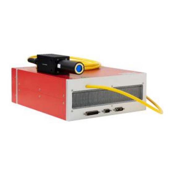
- Page 1 Pulsed Fiber Laser YDFLP-E-80&100-M7-M-R USER MANUAL Version V00...
- Page 2 YDFLP-E-80&100-M7-M-R User Manual Safety Information Please read this manual carefully before operating the YDFLP fiber lasers. In order to ensure the safe operation and optimal performance of the product, please strictly follow the safety notification below. Make sure that the 48V DC power supply is connected in the correct way. Inappropriate ●...
- Page 3 YDFLP-E-80&100-M7-M-R User Manual Table 1 Safety Labels and Labeling Locations Symbols Information Laser Warning Triangle -Label of laser emission (Attached on the cover plate, near the output fiber) Compliance Label (Attached on the cover plate) Product Rating Information (Attached on the cover plate) File Number: JG-MCYF-SM-0039...
-
Page 4: Table Of Contents
2. Laser Interface ........................8 2.1 Power Supply Connector......................8 2.2 RS-232 Control Connector.....................9 2.3 DB25 Control Connector....................... 9 3. JPT GUI Laser Testing Software-TypeE ................. 14 3.1 GUI Operation........................15 3.1.1 Serial Port Connection....................15 3.1.2 Laser Monitoring Function....................16 3.2 Monitoring Function and Alarm Description...............22... -
Page 5: Product Introduction
1. Product Introduction 1.1 Product Description JPT E-M7 Series fiber laser control with standard DB25 interface and powered with 48V DC. It is designed for high-speed and precise marking application. The pulse response and performance are much better comparing to similar products. Significantly compact size is ideal for small marking system. -
Page 6: Operation Conditions And Safety Instructions
YDFLP-E-80&100-M7-M-R User Manual 1.3 Operation Conditions and Safety Instructions Please read the following instructions carefully. Product reliability and lifetime probably be affected if not following the user manual. 1. Make sure that the 48VDC power supply is connected in the correct way. Wrong connection or input voltage might damage the product. -
Page 7: Ydflp Product Naming Convention
YDFLP-E-80&100-M7-M-R User Manual window will cause heat and damage the lens, which results in output power decrease even laser damage. 7. Please make sure that the power is off before installing and uninstalling. 8. Please do not look at the output window anytime when power on, and wear laser safety goggle when operating the fiber laser. -
Page 8: Technical Specifications
YDFLP-E-80&100-M7-M-R User Manual 1.5 Technical Specifications Table 4 Specifications of the E-M7 Series Pulsed Fiber Laser Characteristic\ Laser Type YDFLP-E-80-M7-M-R YDFLP-E-100-M7-M-R M² <1.6 Delivery Cable Length Average Output Power >80 >100 Maximum Pulse Energy Pulse Repetition Rate Range 1-4000 Pulse Width 2-500 Output Power Instability <5... - Page 9 YDFLP-E-80&100-M7-M-R User Manual Table5 E-M7 Series Fiber Laser Cut-off Frequency Value(kHz) YDFLP-E-80&100-M7-M-R Max pulse Pulse Width frequency Cut-off frequency(kHz) (ns) (kHz) YDFLP-E-80-M7-M-R YDFLP-E-100-M7-M-R 1 (CW) 2600 2960 4000 1800 2160 4000 1300 1400 4000 4000 3000 3000 3000 2000 2000 2000 1000 1000...
- Page 10 YDFLP-E-80&100-M7-M-R User Manual Figure 4 YDFLP-E-80&100-M7-M-R Output Waveform Graph. File Number: JG-MCYF-SM-0039...
-
Page 11: Installation Dimensions
YDFLP-E-80&100-M7-M-R User Manual 1.6 Installation Dimensions 1. YDFLP-E-80&100-M7-M-R Laser Dimensions Laser Module Dimensions (Unit: mm) Figure 5 YDFLP-E-80&100-M7-M-R 2. YDFLP-E-80&100-M7-M-R Laser Dimensions Standard Output Head Dimensions (Unit: mm) Figure 6 YDFLP-E-80&100-M7-M-R The isolator head is only for reference. Please be subject to the actual product. File Number: JG-MCYF-SM-0039... -
Page 12: Laser Interface
YDFLP-E-80&100-M7-M-R User Manual 2. Laser Interface 2.1 Power Supply Connector Please refer to Figure7 & Table 6 in below to install the power cable to the 48V DC power supply, and ensure the DC power supply can provide sufficient output power. Please also note the polarity of the cable when connecting. -
Page 13: Rs-232 Control Connector
YDFLP-E-80&100-M7-M-R User Manual 2.2 RS-232 Control Connector RS-232 connector is available for connecting PC or the Red Control card. Customer can monitor and control laser by GUI software, serial commands or red card after connected. Pins definition is shown in below Figure8 & Table 7: Figure 8 RS232 Connector DB9 Table 7 RS-232 Interface Definition PIN#... - Page 14 YDFLP-E-80&100-M7-M-R User Manual Table 8 DB25 Interface Definition DB25 PIN# Definition IP0-IP7 Power Control Latches power setting of the laser, effective during rising edge(This feature can be enabled in the GUI) 10-15 Description: PIN10-15 have connected to the ground inside the fiber laser, only need to connect control card GND with one of the Pins.
- Page 15 YDFLP-E-80&100-M7-M-R User Manual PIN 1~8 Output Power Control PIN1~8 controls the output laser power by TTL signal. The encoding can be set within the range of 0~255, which is corresponding to the 0~100% output power. The actual output laser power may not be a linear relationship with these settings. And the actual output power also related to the frequency.
- Page 16 YDFLP-E-80&100-M7-M-R User Manual D: Frequency sampling time under internal frequency mode, at least 1 complete frequency period before turning on the laser (PA). E: SIMMER value. The first pulse energy can be adjusted via GUI software. Fiber laser control system self-locking: If fiber laser is on abnormal status (eg.frequency signal<1khz, high temperature, low power supply etc.), it will stop working to protect the whole system.
- Page 17 YDFLP-E-80&100-M7-M-R User Manual The first byte of instruction code is 0x01. The Pin22 signal needs to be turned on 10us in advance before sending Pin2 and Pin3 signals. After finished pulse width adjustment, Pin2 and Pin3 signals need ≥ 10us delay before turning off Pin22 signal (as shown in Table 11).
-
Page 18: Jpt Gui Laser Testing Software-Typee
DB25 interface monitoring, internal parameters monitoring etc. Using the matched GUI software for JPT laser is recommended. The GUI software, in addition to set the parameters, also can be used for signal monitoring and troubleshooting etc. -
Page 19: Gui Operation
YDFLP-E-80&100-M7-M-R User Manual 3.1 GUI Operation Software Installation Figure 12 Installation Package and Driver Installation steps: decompress installation package → install driver → install software library → open TypeE-GUI software 3.1.1 Serial COM Port 1) Connecting method Using USB TO RS232 cable to connect PC’s USB and the Laser’s RS-232 connector. After connecting the data line, check the serial port number: my computer →... -
Page 20: Laser Monitoring Function
YDFLP-E-80&100-M7-M-R User Manual 2). Connecting State Figure 14 GUI Disconnected State Figure 15 GUI Connected State 3.1.2 Laser Monitoring Function 1) GUI Control the Emission File Number: JG-MCYF-SM-0039... - Page 21 YDFLP-E-80&100-M7-M-R User Manual Choose the GUI control Mode Figure 16 GUI Full Ctrl mode GUI Full Control mode(GUI Ctrl): When selecting the GUI full Control mode, all the parameters of Internal/External Control mode (eg. power, frequency, pulse width, PA, MO) will change to Internal Control mode.
- Page 22 YDFLP-E-80&100-M7-M-R User Manual Figure 18 Setting parameters and emitting After selecting full control mode, user can set power, frequency, pulse width and then press “edit” button to confirm. User can switch on/off emission when clicking “Laser” button. Note: All the parameters except power can’t be modified during emission. Control MO signal Figure 19 GUI control MO state Ctrl MO: The “MO”...
- Page 23 YDFLP-E-80&100-M7-M-R User Manual Laser priority: Laser is prior when laser and red beam are mutually exclusive. Red priority:Red beam is prior when laser and red beam are mutually exclusive. Laser priority and red beam switching on:Laser and red beam are mutually exclusive. Red beam is enabled by default setting when there is no laser emission(*password is required for this setting).
- Page 24 YDFLP-E-80&100-M7-M-R User Manual [Appropriate Simmer] [High Simmer] [Low Simmer] Lock power: Laser will lock to GUI setting power. Red Power: Brightness of built-in red pilot(optional) can be adjusted, value range is 0-100. External frequency: When selecting external frequency mode, the laser output pulse will be synchronized with external frequency signal.
- Page 25 YDFLP-E-80&100-M7-M-R User Manual External frequency and internal frequency setting examples: [External Frequency] [Internal Frequency] *T=Duration of pulse period, maximum duration ≤ reduction frequency period Pin9Lock: Power latch function is enabled if selected, the value of Pin1 to Pin8 is latched during the rising edge.
-
Page 26: Monitoring Function And Alarm Description
YDFLP-E-80&100-M7-M-R User Manual Figure 22 Optional function of performance mode Selecting “Performance mode” in GUI, the average output power of the laser can be increased by 20% under the same cut-off frequency. The operational environmental temperature range 5~35℃ is recommended at this point.The sensor might be alarm if temperature beyond 5-35℃ and continuous emitting the laser under the high energy. - Page 27 Power current: Monitor the secondary drive current value of the laser. TEC temperature: Monitor the current seed source temperature. System parameter: Internal system parameter setting interface.(For JPT internal use only) Log record:To record the laser setting and alarm. Alarm record:To record the sequence of the latest 10 laser alarms.
- Page 28 YDFLP-E-80&100-M7-M-R User Manual Pump tempOT: The pump temperature is higher than the set temperature. PRE lowE: the pre amplifier low current alarm. Voltage error: Supplying voltage is too low or too high. No pulseE: No seed source backlight signal detected or the seed source backlight signal less than 1kHz.
- Page 29 YDFLP-E-80&100-M7-M-R User Manual Warranty and service terms in User’s Manual are for reference only. Official service and warranty are subject to official contract. File Number: JG-MCYF-SM-0039...
Need help?
Do you have a question about the YDFLP-E-80&100-M7-M-R and is the answer not in the manual?
Questions and answers