Table of Contents
Advertisement
Please read this user manual carefully before operating the YDFLP fiber laser. It provides
essential information regarding safety, product operation, and other necessary reference
information. For the purpose of safety operation and maximizing the performance of the fiber
laser, please strictly follow the safety notifications as below:
Make sure the +24VDC power supply is connected in the correct way. Inappropriate
●
connection might spoil the product.
You can't open the cover of this product without the permission of JPT. It might cause
●
safety issues and invalidate the warranty.
Please wear laser goggle, as shown in Fig. 1, all the time during the operation. This laser
●
module carry a Class 4 Laser rating it emits invisible laser radiation(1064 central emission
wavelength)with a rated average output power of over 10W and rated peak power of over 7kW.
Contact with direct or scattered laser radiation will cause permanent damage to the eyes, burn
human tissue and start fires.
Attention: Even at 0% power setting, the average output power is still about 90mW.
●
File Number: EFLP001-B-E
Safety
Table 1 Safety Labels
Symbols
Shenzhen JPT Opto-electronics Co. Ltd.
1
YDFLP Fiber Laser Installation
Guide and User Manual
Information
Laser Warning Triangle -L
abel of laser emission (At
tached near the output fib
er)
Component for Incorporati
on labeling (Attached at t
he upper cover of this pro
duct)
Version : V05 Date:2017
Advertisement
Table of Contents

Subscribe to Our Youtube Channel
Related Manuals for JPT YDFLP


Summary of Contents for JPT YDFLP
-
Page 1: Safety
Make sure the +24VDC power supply is connected in the correct way. Inappropriate ● connection might spoil the product. You can’t open the cover of this product without the permission of JPT. It might cause ● safety issues and invalidate the warranty. - Page 2 YDFLP Fiber Laser Installation Guide and User Manual Safety Information (Attach ed at the upper cover of t his product) Safety Warning (Attached on the output fiber isolato r & collimator) Figure 1 Laser Safety Goggle File Number: EFLP001-B-E Shenzhen JPT Opto-electronics Co. Ltd.
-
Page 3: Table Of Contents
REPARATORY EXAMINATION OF THE PRODUCT 4.2 O ........................... 15 PERATION ROCEDURE 4.3 P ....................15 RECAUTIONS DURING THE LASER OPERATION 5. JPT GUI LASER TESTING SOFTWARE......................16 5.1 S &I ....................16 OFTWARE NSTALLATION NTRODUCTION 5.1.1 Installation: ............................... 16 5.1.2.Introduction .............................. -
Page 4: Product Tour
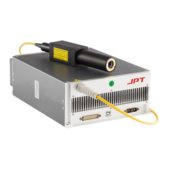
JPT’s MOPA fiber laser adopts the standard DB25 interface, and it is power supplied with 24V/8A DC power supply, which makes it a good compatibility. A photograph of a typical JPT MOPA fiber laser is as shown in Figure 2. -
Page 5: Packaging List
6) Never look at the fiber laser head, and please wear laser goggle when operate this fiber laser; 7) The YDFLP-X-RE/LP(1/2)+-X-X pulse width is fixed at 200ns. If you need other fixed pulse width, please contact us for customization; File Number: EFLP001-B-E Shenzhen JPT Opto-electronics Co. -
Page 6: Ydflp Product Series Naming Convention
Table 3 Naming Convention for Pulsed Fiber Laser For example: YDFLP-20-M1+-S: Means this is a standard product of M1+ using single mode type of optical fiber with the nominal output power @ 20W. YDFLP-C-20-M1+-S: Means compact size 20w M1+ laser, single mode. -
Page 7: Technical Specifications
YDFLP Fiber Laser Installation Guide and User Manual 1.5 Technical Specifications Table 4 Specifications of the LP series pulsed fiber laser Laser Type Unit MOPA Power <1.8 <1.3 <1.3 <1.5 <1.8 Laser Model LP2+-L1 LP1+-S LP1+-S RE+-S LP1+-L1 Output Fiber Length Average Power >30... - Page 8 YDFLP Fiber Laser Installation Guide and User Manual Table 5 Threshold Frequency(kHz)of LP series laser Pulse width(ns) 30-LP2+-L1 30-LP1+-S 20-LP1+-S 20-RE+-S 60-LP1+-L1 30khz 37khz 30khz 30Khz 50Khz The cut-off frequency is the minimum frequency that the laser can be operated with maximum peak power and average power.
-
Page 9: Installation
YDFLP Fiber Laser Installation Guide and User Manual 2. Installation 2.1 Dimensions 1.Dimension of main body LP series 20/30W LP series 60W Figure 4 Mechanical Dimensions of the fiber laser module (Unit: mm) File Number: EFLP001-B-E Shenzhen JPT Opto-electronics Co. Ltd. - Page 10 YDFLP Fiber Laser Installation Guide and User Manual 1. Mechanical Dimensions of the output isolator RE/LP(1/2) +-S 20/30W LP(1/2)+-L1 20/30W LP series 60W Figure 5 Mechanical Dimensions of the output isolator (Unit: mm) 3. Mechanical Dimensions of the output fiber cable...
-
Page 11: Installation Procedures
YDFLP Fiber Laser Installation Guide and User Manual 3 0 0 0 LP series 60W Firgure 6 fiber cable length 2.2 Installation Procedures 1) Fix the laser module onto the mounting panel; make sure enough air gaps around the laser module for sufficient air flow. -
Page 12: Control And Monitoring Interfaces
YDFLP Fiber Laser Installation Guide and User Manual 3. Control and Monitoring Interfaces 3.1 Control Interface DB25 behind the power module is the interface used to connect the control system (such as marking machines) to the laser system. Please make sure that the interface is connected firmly before the operation. - Page 13 YDFLP Fiber Laser Installation Guide and User Manual MO signal for turn on/off high level is just as open and low level is just as off. The laser will shooting after turning on the laser for 1s together with the rising of MO...
- Page 14 YDFLP Fiber Laser Installation Guide and User Manual Below is the DB25 control timing diagram: Figure 9 DB25 Controlling Time Series Diagram A--System Initialization: The laser can accept signal only after 12s switch on the laser power. B--Pump charging time: Range (8ms-35ms), 8ms is recommended.
-
Page 15: Operation Procedure
YDFLP Fiber Laser Installation Guide and User Manual 4. Operation Procedure 4.1 Preparatory examination of the product 1)Check the laser casing and the fiber cable for any unexpected conditions; 2)Check the connection between laser system and the fiber laser module, and tighten the connection cable. -
Page 16: Jpt Gui Laser Testing Software
YDFLP Fiber Laser Installation Guide and User Manual 5. JPT GUI Laser Testing Software. Software Installation &Introduction 5.1.1 Installation: Unzip the installation package Install the Driver Install vC2008-x86 Start Software File Number: EFLP001-B-E Shenzhen JPT Opto-electronics Co. Ltd. Version : V05 Date:2017... -
Page 17: Introduction
YDFLP Fiber Laser Installation Guide and User Manual 5.1.2.Introduction 1. JPTlaser GUI has below functions:Laser_Control,Default_SET,Operate Prompt,Feedback Prompt,Control_Mode,Laser_STA,DB25 Port Monitor,Laser SYS,etc. 2. All setting and change on GUI will work immediately,no need to restart, 3. The “Default_SET” and “Control Mode” have power-off protection function for the parameter, 4. -
Page 18: Use Gui To Control Laser
YDFLP Fiber Laser Installation Guide and User Manual 5.2.2 Use GUI to Control Laser 1) Control Mode Option When we select all parameters controlled by GUI. The setting will be saved and has data power-off memory function. Therefore, we should cancel the GUI_Control mode each time when we don’t want to use GUI to control the laser. - Page 19 YDFLP Fiber Laser Installation Guide and User Manual Def_SIMMER: To control the amplitude of the first pulse. The larger the value is, the higher the first pulse will be. [Suitable SIMMER] [Too High SIMMER] [Too Low SIMMER] Def_PRR: Under internal PRR mode, the system will output based on the default PRR if no external frequency signal is detected.
-
Page 20: Laser System Setting
YDFLP Fiber Laser Installation Guide and User Manual 5.2.3 Laser System Setting Laser-SYS for JPT engineer to set laser system parameters, it need right password to input any parameter change.Not open to customers in current version. 5.2.4 Laser Working Status Monitoring From Laser_STA, parameters and alarms can be monitored. -
Page 21: Maintenance, Customer Service And Repair
JPT personnel. All requests for repair or replacement under this warranty must be made as soon as possible after the defect has been noticed and must be directed to JPT or its representative in your area. Items authorized for return by us must be returned in a suitable container. Any File Number: EFLP001-B-E Shenzhen JPT Opto-electronics Co. - Page 22 YDFLP Fiber Laser Installation Guide and User Manual damage noted upon receipt of the unit must be documented for appropriate claim against the carrier. Product warranty and service terms above are for users’ reference only. Official service and warranty scope will be specified in the contract.
Need help?
Do you have a question about the YDFLP and is the answer not in the manual?
Questions and answers