Table of Contents
Advertisement
Please read this user manual carefully before operating the YDFLP fiber laser. It provides
essential information regarding safety, product operation, and other necessary reference
information. For the purpose of safety operation and maximizing the performance of the fiber
laser, please strictly follow the safety notifications as below:
Make sure the +24VDC power supply is connected in the correct way. Inappropriate
●
connection might spoil the product.
You can't open the cover of this product without the permission of JPT. It might cause
●
safety issues and invalidate the warranty.
Please wear laser goggle, as shown in Fig. 1, all the time during the operation. This laser
●
module carry a Class 4 Laser rating it emits invisible laser radiation with a rated average output
power of over 10W and rated peak power of over 7kW. Contact with direct or scattered laser
radiation will cause permanent damage to the eyes, burn human tissue and start fires.
Attention: Even at 0% power setting, the average output power is still about 90mW.
●
File Number: EFLP001‐B‐E
Safety
Table 1 Safety Labels
Symbols
Shenzhen JPT Opto‐electronics Co. Ltd.
1
YDFLP Fiber Laser Installation
Guide and User Manual
Information
Laser Warning Triangle ‐La
bel of laser emission (Att
ached near the output fib
er)
Component for Incorporati
on labeling (Attached at t
he upper cover of this pr
oduct)
Version:B Date:2016.4
Advertisement
Table of Contents

Related Manuals for JPT YDFLP


Summary of Contents for JPT YDFLP
-
Page 1: Safety
Make sure the +24VDC power supply is connected in the correct way. Inappropriate ● connection might spoil the product. You can’t open the cover of this product without the permission of JPT. It might cause ● safety issues and invalidate the warranty. - Page 2 YDFLP Fiber Laser Installation Guide and User Manual Safety Information (Attach ed at the upper cover of this product) Safety Warning (Attached on the output fiber isolat or & collimator) Figure 1 Laser Safety Goggle File Number: EFLP001‐B‐E Shenzhen JPT Opto‐electronics Co. Ltd.
-
Page 3: Table Of Contents
YDFLP Fiber Laser Installation Guide and User Manual Contents SAFETY ..................................1 CONTENTS ................................. 3 1. PRODUCT TOUR ..............................4 1.1 P ............................4 RODUCT ESCRIPTION 1.2 P ..............................5 ACKAGING 1.3 O ..................5 PERATION CONDITIONS AND SAFETY INSTRUCTIONS 1.4 YDFLP P... -
Page 4: Product Tour
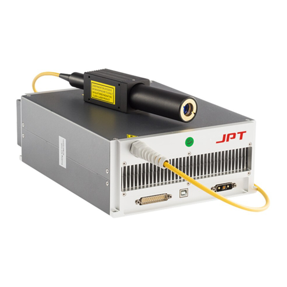
JPT’s MOPA fiber laser adopts the standard DB25 interface, and it is power supplied with 24V/8A DC power supply, which makes it a good compatibility. A photograph of a typical JPT MOPA fiber laser is as shown in Figure 2. -
Page 5: Packaging List
5) Power off the product before installing or uninstalling this fiber laser; 6) Never look at the fiber laser head, and please wear laser goggle when operate this fiber laser; 7) The YDFLP-M6+ contains 16 pulse width to choose: 1ns,2ns,4ns,6ns,9ns,13ns,20ns,30ns, 45ns,55ns,60ns,80ns,100ns,150ns,200ns,250ns.If you need other pulse width, please contact us for customization. -
Page 6: Ydflp Product Series Naming Convention
Table 3 Naming Convention for Pulsed Fiber Laser For example: YDFLP- 20—M1+—S: Means this is a standard product of M1+ using single mode type of optical fiber with the nominal output power @ 20W. YDFLP- 30—M1+—L—R: Means this is a customized product of M1+ using low mode type of optical fiber with the nominal output power @ 30W,Integrated built-in red pilot laser. -
Page 7: Technical Specifications
YDFLP Fiber Laser Installation Guide and User Manual 1.5 Technical Specifications Table 4 Specifications of the YDFLP-M6+ fiber laser Laser Type Unit MOPA Product Model YDFLP‐20‐M6+‐S Average Output Power W <1.3 Output Fiber Length 2m (Customizable) Pulse Energy 0.5 Full Power Frequency Range 40‐2000 Adjustable Frequency Range 1‐2000 Pulse Width Range 1‐250 Output Power Stability <5 Cooling Method ... - Page 8 YDFLP Fiber Laser Installation Guide and User Manual Table 5 YDFLP-M6+ Threshold Frequency YDFLP‐20‐M6+‐S Pulse Width (ns) Threshold Frequency(KHz) 1 1600 2 4 6 9 13 20 30 45 55 60 80 100 150 200 250 File Number: EFLP001‐B‐E Shenzhen JPT Opto‐electronics Co. Ltd. Version:B Date:2016.4 ...
- Page 9 YDFLP Fiber Laser Installation Guide and User Manual ≥80ns ≥ For safety concern, when pulse width , frequency 400 kHz, input and output frequency is as shown in the figure below: *Above the cut-off Frequency value is the fiber laser full power output range, oppositely, below the cut-off frequency value is the cut-off power output range.
- Page 10 YDFLP Fiber Laser Installation Guide and User Manual Figure 4 Waveform curve of M6+-S Figure 5 The actual output power curve of M6+ full loaded at different pulse width and frequency File Number: EFLP001‐B‐E Shenzhen JPT Opto‐electronics Co. Ltd. Version:B Date:2016.4 ...
- Page 11 YDFLP Fiber Laser Installation Guide and User Manual Figure 6 The actual power curve of M6+@ 2ns at different simmer value and frequency ※ M6+ can use GUI to adjust the Class II simmer value to achieve customer required effect. The changes of simmer value will influence the output power under the same parameters.
-
Page 12: Installation
YDFLP Fiber Laser Installation Guide and User Manual 2. Installation 2.1 Dimensions 1.Dimension of main body Figure 7 Mechanical Dimensions of the fiber laser module (Unit: mm) 2. Mechanical Dimensions of the output isolator Figure 8 Mechanical Dimensions of the output isolator (Unit: mm) File Number: EFLP001‐B‐E... - Page 13 YDFLP Fiber Laser Installation Guide and User Manual 3. Mechanical Dimensions of the output fiber cable The exact size of isolator please in kind prevail. 2.2 Installation Procedures 1) Fix the laser module onto the mounting panel, make sure enough air gaps around the laser module for sufficient air flow.
-
Page 14: Control And Monitoring Interfaces
YDFLP Fiber Laser Installation Guide and User Manual 3. Control and Monitoring Interfaces 3.1 Control Interface DB25 behind the power module is the interface used to connect the control system (such as marking machines) to the laser system. Please make sure that the interface is connected firmly before the operation. - Page 15 YDFLP Fiber Laser Installation Guide and User Manual 20 Frequency Modulation (TTL) 22 A. Control the pulse width ENABLE B. High Level: Red Beam Turned On; Low Level: Red Beam Turned Off. 18 MO signal for turn on/off high level is just as open and low level is just as off. The laser will shooting after turning on the laser for 12s together with the rising of MO 9,17,23,24,25 No need to connect 3.1.1 Interface Setting Please set the current of pump laser diode which is the output power through a combination of TTL signals of PIN1~8.
-
Page 16: Pulse Width Control
YDFLP Fiber Laser Installation Guide and User Manual DB25 Controlling Time Series Diagram Figure 11 DB25 Controlling Time Series Diagram A System initialization time: The laser will shooting after turning on the laser for 12s together with the rising of MO ... - Page 17 YDFLP Fiber Laser Installation Guide and User Manual Table 8 Fiber laser pulse width control pin and signal Pin No. Item Description Fiber laser serial input, setting data bits synchronize with 2 Serial Input serial clock rising edge Serial digital clock, 8kHz≦Clock 3 Serial Clock Frequency≦10kHz,suggest to use 10KHZ Pulse width control function: 22 Enable High: Enable,Pin2 and Pin3 to control the pulse width Low or Not connection: Disable 3.2.2 Pulse width control instruction structure 1) Control system send the serial input instruction to fiber laser through Pin2, meanwhile send the clock signal through Pin3.
- Page 18 YDFLP Fiber Laser Installation Guide and User Manual It will waste 50ns to finish the fiber laser pulse width initialization. Remarks: If Instruction code transmit 3 * 0x01 instruction, the fiber laser will refuse to receipt. 3.2.4 Pulse width control clock diagram...
-
Page 19: Operation Procedure
YDFLP Fiber Laser Installation Guide and User Manual 4. Operation Procedure 4.1 Preparatory examination of the product 1)Check the laser casing and the fiber cable for any unexpected conditions; 2)Check the connection between laser system and the fiber laser module, and tighten the connection cable. -
Page 20: Maintenance, Customer Service And Repair
JPT has the right to selectively repair or replace the products which prove to be defective during the warranty period and which shall be returned. The customer will be charges for the cost of repairing the product if the product is not under warranty or if the repair is not cover under the warranty. - Page 21 YDFLP Fiber Laser Installation Guide and User Manual as possible after the defect has been noticed and must be directed to JPT or its representative in your area. Items authorized for return by us must be returned in a suitable container. Any damage noted upon receipt of the unit must be documented for appropriate claim against the carrier.
Need help?
Do you have a question about the YDFLP and is the answer not in the manual?
Questions and answers