
Related Manuals for JPT YDFLP-E-20-M7-S-R


Summary of Contents for JPT YDFLP-E-20-M7-S-R
- Page 1 YDFLP-E-20/30-M7 User Manual Pulsed Fiber Laser YDFLP-E-20/30-M7-S-R USER MANUAL Version 1.4 File Number: J-SI-0036...
-
Page 2: Sa F E T Y In F O Rm A T I O N
YDFLP-E-20/30-M7 User Manual Safety Information Please read this manual carefully before operating the YDFLP fiber lasers. In order to ensure the safe operation and optimal performance of the product, please strictly follow the safety notification below. Make sure that the 24V DC power supply is connected in the correct way. Inappropriate ●... - Page 3 YDFLP-E-20/30-M7 User Manual Compliance Label (Attached on the cover plate) Product Rating Information (Attached on the cover plate) Figure 1 Laser Safety Goggle File Number: J-SI-0036...
-
Page 4: Table Of Contents
OWER UPPLY ABLE AND NTERFACE NSTALLATION 3.2 RS232 C ............................10 ONNECTOR 3.3 C ............................11 ONTROL NTERFACE 4. JPT GUI LASER TESTING SOFTWARE-TYPEE................... 16 4.1 GUI I ............................17 NTRODUCTION 4.2 L ........................23 ASER ONITORING UNCTION File Number: J-SI-0036... -
Page 5: Product Introduction
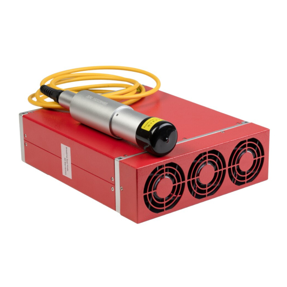
1. Product Introduction 1.1 Product Description JPT M7 Series fiber laser control with standard DB25 interface and powered with 24V DC. It is designed for high-speed and precise marking application. The pulse response and performance are much better comparing to similar products. Significantly compact size is ideal for small marking system. -
Page 6: Ydflp Product Series Naming Convention
YDFLP-E-20/30-M7 User Manual 1.3.2. Make sure that the bending diameter of the fiber cable is larger than 15cm in anytime. Otherwise power will decrease or the laser may even be damaged. 1.3.3. The speed of the fan is adjustable according to ambient temperature. Make sure that minimum10cm air gaps behind and in front of the fiber laser. -
Page 7: Technical Specifications
YDFLP-200-M7-H-R: Customized M7, using high mode type of optical fiber with the nominal output power 200W, built-in red pilot laser. 1.5 Technical Specifications Table 3 Specifications of the YDFLP-E-M7-S-R fiber laser Characteristic\ Laser Type YDFLP-E-20-M7-S-R YDFLP-E-30-M7-S-R M² <1.4 Delivery Cable Length Average Output Power >20... - Page 8 YDFLP-E-20/30-M7 User Manual Table 4 YDFLP-M7-S Cut-off Frequency Value(kHz) YDFLP-E-20&30-M7-S-R Maximum Cut-off frequency(kHz) Pulse Width pulse frequency (ns) YDFLP-E-20-M7-S-R YDFLP-E-30--M7-S-R (kHz) 1(CW) 1300 4000 4000 4000 4000 3000 3000 3000 2000 2000 2000 1000 1000 1000 *For laser safety and long lifetime concern, when pulse width set ≥80ns, frequency range will be limited at 400kHz.
- Page 9 YDFLP-E-20/30-M7 User Manual igure 4 YDFLP-E-20&30-M7-S-R Output Waveform Graph. File Number: J-SI-0036...
-
Page 10: Installation
YDFLP-E-20/30-M7 User Manual 2. Installation 2.1 Dimension 2.1.1 Dimension of main body Figure 5 YDFLP-E-20/30-M7-S-R Laser Module Dimensions (Unit: mm) 2.1.2 Mechanical Dimension of the output isolator(round shape). Figure 6 YDFLP-E-20/30-M7-S-R Standard Isolated Output Head Dimensions (Unit: mm) The isolator head is only for reference. Please be subject to the actual product. File Number: J-SI-0036... -
Page 11: Laser Interface
YDFLP-E-20/30-M7 User Manual 3. Laser Interface 3.1 Power Supply Connector The length of standard power cord for laser is around 1250mm. Please refer to Figure 12 & Table 6 in below to install the power cable to the 24V DC power supply,and ensure the DC power supply can provide enough output power. -
Page 12: Rs232 Connector
YDFLP-E-20/30-M7 User Manual 3.2 RS232 Connector Figure 8 RS232 connector-DB9 RS-232 Interface Definition Table 6 PIN# Description 1,4,6-9 No need to connect 3.3 Control Interface DB25 behind the power module is the interface used to connect the control system (such as marking machines) to the laser system. - Page 13 YDFLP-E-20/30-M7 User Manual edge is effective. 10-15 Description: PIN10-15 have connected with each other inside fiber laser, control card GND only need to control with one of them. Warning signal 16,21 Description:16 low level,21 high level: Normal 16 low level,21 low level: temperature alarm Laser starting signals (PA) shows that high level is open and low level is just as off.
- Page 14 YDFLP-E-20/30-M7 User Manual 3.3.1 Interface Setting Please set the current of pump laser diode which is the output power through a combination of TTL signals of PIN1~8. The encoding can be set within the range of 0~255 which is corresponding to the 0~100% power output power (the actual optical power output may not be a linear relationship with these settings).
- Page 15 YDFLP-E-20/30-M7 User Manual 3.3.1.1 DB25 Sequence SUPPLY VOLTAGE 24V PIN18 MO PIN19 PA PIN20 PRR PUMP CURRENT LASER OUTPUT Figure 10 Diagram of DB25 Control Time Sequence A:12 seconds System initialization time B:MO and PA signal delay time: range(8ms-35ms), recommend 8ms. ...
- Page 16 YDFLP-E-20/30-M7 User Manual Pulse width control function: Enable High: Enable, Pin2 and Pin3 to control the pulse width Low or Not connection: Disable Pulse width control instruction Send instruction to Pin2 of DB25 connector and send clock signal to Pin3 at the same time.
-
Page 17: Jpt Gui Laser Testing Software-Typee
(refer to the specifications of various versions for specific pulse width). If the given pulse width is out of the range, the laser will output with the close pulse width value. 4. JPT GUI Laser Testing Software-TypeE TypeE is designed for M7 series laser. It has multiple functions including laser control, setting the default parameters, setting the control mode, alarm monitoring, DB25 interface monitoring, internal parameters monitoring etc. -
Page 18: Gui Introduction
YDFLP-E-20/30-M7 User Manual 4.1 GUI Introduction 4.1.1 Serial COM Port 4.1.1.1 Connecting method Using USB TO RS232 cable to connect PC’s USB to the Laser’s RS-232 connector. After connecting the data line, check the serial port number: my computer → properties →... - Page 19 YDFLP-E-20/30-M7 User Manual 4.1.1.2. Connecting State Figure 13 GUI Disconnected State Figure 14 GUI Connected State File Number: J-SI-0036...
- Page 20 YDFLP-E-20/30-M7 User Manual 4.1.2 GUI control function 4.1.2.1 GUI control the emission Choose the GUI control Mode Figure 15 GUI Full Ctrl mode GUI Full Control mode(GUI Ctrl):When selecting the GUI full Control mode, all the parameters of Internal/External Control mode (EG. power, frequency, pulse width, PA, MO) will change to Internal Control mode.
- Page 21 YDFLP-E-20/30-M7 User Manual Figure 17 Setting parameters and emitting After selecting full control mode, user can set power, frequency, pulse width and then press “edit” button to confirm. User can switch on/off emission when clicking “Laser” button. Note: All the parameters except power can’t be modified during emission. Control MO signal Figure 18 GUI control MO state Ctrl MO: The “MO”...
- Page 22 YDFLP-E-20/30-M7 User Manual Figure 19 Default parameter settings and selection Lock PRR: Laser will lock to GUI setting frequency. Default pulse: The laser will use GUI default pulse when no pulse width control command received. Simmer:Can be used for controlling the height of the first pulse, the higher the value, the larger the first pulse.
- Page 23 YDFLP-E-20/30-M7 User Manual [Low Simmer] Default pulse width: If the external control fails to provide the pulse width signal, the laser will work according to the default pulse width window setting value. Default frequency: If the external control fails to provide frequency signal, the laser will work according to the default frequency window setting value.
-
Page 24: Laser Monitoring Function
YDFLP-E-20/30-M7 User Manual [Internal Frequency] *T=Duration of pulse period, maximum duration ≤ reduction frequency period 4.2 Laser Monitoring Function The monitoring function of TypeE software can observe some operation parameters and alarm conditions. The laser will send the number of alarms saved in the system to the GUI software each time when it is turned on. - Page 25 YDFLP-E-20/30-M7 User Manual Voltage error: alarm when supplying voltage is too low or too high. DB25-D7-D0: monitor the current power signal of the laser, corresponding to the 8-bit binary mode. D0 is the lowest bit, D7 is the highest bit, and the green light is the status of the received signal of this bit.
Need help?
Do you have a question about the YDFLP-E-20-M7-S-R and is the answer not in the manual?
Questions and answers