Table of Contents
Advertisement
Advertisement
Table of Contents

Related Manuals for JPT LP Series


Summary of Contents for JPT LP Series
- Page 1 Pulsed Fiber Laser YDFLP-E-20&30&50-LP USER’S MANUAL Version...
- Page 2 YDFLP-E-20&30&50-LP User’s Manual Safety Information Please read this manual carefully before operating the YDFLP fiber lasers. In order to ensure the safe operation and optimal performance of the product, please strictly follow the safety notification below. Make sure the +24VDC power supply is connected in the correct way. Inappropriate ●...
- Page 3 YDFLP-E-20&30&50-LP User’s Manual Table 1 Safety Labels and Labeling Locations Symbols Information Laser Warning Triangle -Label of laser emission (Attached on the cover plate, near the output fiber) Compliance Label (Attached on the cover plate) Product Rating Information (Attached on the cover plate) File Number: S-PI-0033...
-
Page 4: Table Of Contents
2.2 RS-232 Control Connector ....................10 2.3 DB25 Control Connector ..................... 10 2.4 DB25 Control & Sequence ....................12 3. JPT GUI Laser Testing Software-TypeE ................13 3.1 GUI Operation ........................13 3.1.1 Serial COM port ....................... 13 3.1.2 GUI control function ......................15 3.2 Laser monitoring function .................... -
Page 5: 1.Product Introduction
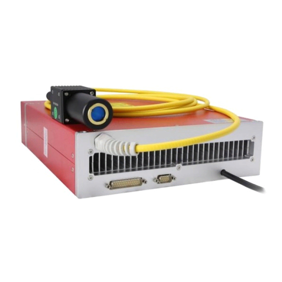
1.Product Introduction 1.1 Product Description JPT E type fiber laser control with standard DB25 interface and powered with 24V/5A(10A) DC. It is designed for high speed and precise marking applications. The pulse response and performance are much better comparing to the similar products. Significantly compact size is perfect for smaller marking system. -
Page 6: Operation Conditions And Safety Instructions
YDFLP-E-20&30&50-LP User’s Manual 1.3 Operation conditions and safety instructions Please read the following instructions carefully. Product reliability and lifetime probably be effected if not following the user’s manual. 1) Make sure the +24VDC power supply is connected in the correct way. Wrong connection or input voltage might damage the product. -
Page 7: Ydflp Product Naming Convention
1、 Product Name :Ytterbium Doped Fiber Laser Pulse (YDFLP) 2、 Product type 3、 Average Output power 4、 Pulse Characteristics: M series - adjustable pulse width LP series - fixed pulse width 5、 Optical Fiber attributes:S: Single mode, M²<1.5 L: Low mode, M²<1.8 H: High mode, M²>2.5 6、... -
Page 8: Technical Specifications
YDFLP-E-20&30&50-LP User’s Manual 1.5 Technical Specifications Table 4 Specifications of the LP series pulsed fiber laser Characteristic\Laser Type Unit E-20-LP-S E-30-LP-S E-50-LP-L <1.5 <1.8 M² Delivery Cable Length Average Output Power >20 >30 >50 Maximum Pulse Energy 1.25 Pulse Frequency Range... - Page 9 YDFLP-E-20&30&50-LP User’s Manual Table 5 LP Series Fiber Laser Power Reduction Frequency Value(kHz) YDFLP-E-20-LP-S YDFLP-E-30-LP-S YDFLP-E-50-LP-L ★ The maximum output frequency will be limited to 600kHz. *The laser will have expected output power when working above power reduction frequency. When working below power reduction frequency, the power will drop accordingly to maintain the output peak power.
- Page 10 YDFLP-E-20&30&50-LP User’s Manual P/kW 9.00 8.00 7.00 6.00 5.00 4.00 3.00 2.00 1.00 0.00 t/ns Figure 5 YDFLP-E-20&30-LP-S Output waveform graph P/kW 10.00 9.00 8.00 7.00 6.00 5.00 4.00 3.00 2.00 1.00 0.00 t/ns Figure 6 YDFLP-E-50-LP-L Output waveform graph File Number: S-PI-0033...
-
Page 11: Installation Dimensions
YDFLP-E-20&30&50-LP User’s Manual 1.6 Installation Dimensions 1)YDFLP-E-20&30-LP-S Laser dimensions Figure 7 YDFLP-E-20&30-LP-S Laser module dimensions (Unit:mm) Figure 8 YDFLP-E-20-LP-S Standard isolated output head dimensions (Unit:mm) Figure 9 YDFLP-E-30-LP-S Standard isolated output head dimensions (Unit:mm) The output isolator head is only for reference. Please be subject to the actual product. File Number: S-PI-0033... - Page 12 YDFLP-E-20&30&50-LP User’s Manual 2)YDFLP-E-50-LP-L Laser dimensions Figure 10 YDFLP-E-50-LP-L Dimensions of fiber laser module(Unit:mm) Figure 11 YDFLP-E-50-LP-L Dimensions of fiber laser module(Unit:mm) The output isolator head is only for reference. Please be subject to the actual product. File Number: S-PI-0033...
-
Page 13: Laser Interface
YDFLP-E-20&30&50-LP User’s Manual 2. Laser Interface 2.1 Power Supply Connector The length of standard power cord for laser is around 1250mm. Please refer to Figure 12 & Table 6 in below to install the power cable to the 24V DC power supply,and ensure the DC power supply can provide enough output power. -
Page 14: Rs-232 Control Connector
YDFLP-E-20&30&50-LP User’s Manual 2.2 RS-232 Control Connector RS-232 connector is available for connecting PC or red card. Customer can monitor and control laser by E type software, serial commands or red card after connected. Pins definition is shown in below Figure13 & Table 7: Figure 13 RS232 connector DB9 Table 7 RS-232 Interface definition PIN#... - Page 15 YDFLP-E-20&30&50-LP User’s Manual Table 8 DB25 interface definition DB25 PIN# Definition IP0-IP7 Power Control Latches power setting into the laser by rising edge 10-15 Description: PIN10-15 have connected to the ground inside the fiber laser, only need to connect control card GND with one of Pins. Warning signal 16,21 Description:16 low level,21 high level: Normal...
-
Page 16: Db25 Control & Sequence
YDFLP-E-20&30&50-LP User’s Manual 2.4 DB25 Control & Sequence 1) Output power control PIN1~8 controls the output laser power by TTL signal. The encoding can be set within the range of 0~255 which is corresponding to the 0~100% output power. The actual output laser power may not be a linear relationship with these settings. -
Page 17: Jpt Gui Laser Testing Software-Typee
24V power supply etc.), it will stop working to protect the whole system. Please restart the fiber laser. Error messages are recorded in E type software. 3. JPT GUI Laser Testing Software-E type E type is designed for YDFLP-E series laser. It has multiple functions including laser control, setting the default parameters, setting the control mode, alarm monitoring, DB25 interface monitoring, internal parameters monitoring etc. - Page 18 YDFLP-E-20&30&50-LP User’s Manual Figure 16 The selection of GUI Serial Port connection 2) Connecting state Figure 17 GUI disconnected state File Number: S-PI-0033...
-
Page 19: Gui Control Function
YDFLP-E-20&30&50-LP User’s Manual Figure 18 GUI connected state 3.1.2 GUI control function 1) GUI control the emission ① Choose the GUI control Mode Figure 19 GUI Full Ctrl mode GUI Full Control mode(GUI Ctrl):When selecting the GUI full Control mode, all the parameters of Internal/External Control mode (EG. - Page 20 YDFLP-E-20&30&50-LP User’s Manual be changed to the previous free control mode setting. User can select this mode to test the emission of laser temporarily. Figure 20 Free Ctrl mode Free Control Mode (Free Ctrl): When selecting free Control mode, user can choose parameter control mode individually.
- Page 21 YDFLP-E-20&30&50-LP User’s Manual Ctrl MO: The “MO” button will be appeared on the interface after selecting Ctrl MO. User can control the switching of MO signal while clicking this button. This setting will not be preserved after power off. 2) Default parameter setting and selection E type software can modify laser default parameter setting and selection in the option of "Parameter setting"...
- Page 22 YDFLP-E-20&30&50-LP User’s Manual Laser_start Output pulse [High Simmer] Laser_start Output pulse [Low Simmer] Lock power: Laser will lock to GUI setting power. Red Power: Brightness of built-in red pilot(optional) can be adjusted, value range is 0-100. External frequency: When selecting external frequency mode, the laser output pulse will be synchronized with external frequency signal.
-
Page 23: Laser Monitoring Function
YDFLP-E-20&30&50-LP User’s Manual Laser_start EXT.FRE Output pulse [Internal Frequency] *T=Duration of pulse period, maximum duration ≤ cut off frequency period Pin9Lock:Power latch function is enabled if selected, rising edge is effective. Default setting is not selected. Pin23Stop:Emergency stop function is enabled if selected, low level is effective. Default setting is not selected Fan Speed Control:The laser fan speed will be control according to the value of the built-in temperature sensor. - Page 24 Pump temperature: Monitor the temperature of optical module. Power current: Monitor the post amplifier driving current value of the laser. System parameter: Internal system parameter setting interface (For JPT internal use only). Log record: To record the laser setting and alarm.
Need help?
Do you have a question about the LP Series and is the answer not in the manual?
Questions and answers