Table of Contents
Advertisement
Quick Links
Please read this user manual carefully before operating the YDFLP fiber laser. It provides
essential information regarding safety, product operation, and other necessary reference
information. For the purpose of safety operation and maximizing the performance of the fiber
laser, please strictly follow the safety notifications as below:
Make sure the +48VDC power supply is connected in the correct way. Inappropriate
●
connection might spoil the product.
You can't open the cover of this product without the permission of JPT. It might cause
●
safety issues and invalidate the warranty.
Please wear laser goggle, as shown in Fig.1, all the time during the operation. This laser
●
module carry a Class 4 Laser rating it emits invisible laser radiation with a rated average output
power of over 10W and rated peak power of over 7kW. Contact with direct or scattered laser
radiation will cause permanent damage to the eyes, burn human tissue and start fires.
Attention: Even at 0% power setting, the average output power is still about 3W.
●
YDFLP-150/200-M7-L1-X user manual
Safety
Table 1 Safety Labels
Symbols
Shenzhen JPT Opto -Electronics Co. Ltd.
1
Information
Laser Warning Triangle -La
bel of laser emission (Att
ached near the output fib
er)
CAUTIONS IN USE(Attach
ed on the
cover plate)
Version :B Date:2018.9
Advertisement
Table of Contents

Related Manuals for JPT YDFLP-150-M7-L1-X


Summary of Contents for JPT YDFLP-150-M7-L1-X
- Page 1 Make sure the +48VDC power supply is connected in the correct way. Inappropriate ● connection might spoil the product. You can’t open the cover of this product without the permission of JPT. It might cause ● safety issues and invalidate the warranty.
- Page 2 YDFLP-150/200-M7-L1-X user manual Parameter Information (Attached on the cover plate) Figure 1 Laser Safety Goggle Shenzhen JPT Opto -Electronics Co. Ltd. Version :B Date:2018.9...
-
Page 3: Table Of Contents
HECK THE STATE OF THE LASER 5. OPERATION PROCEDURE ..........................22 5.1 P ....................22 REPARATORY EXAMINATION OF THE PRODUCT 5.2 O ........................... 22 PERATION ROCEDURE 5.3 P ....................23 RECAUTIONS DURING THE LASER OPERATION Shenzhen JPT Opto -Electronics Co. Ltd. Version :B Date:2018.9... -
Page 4: Product Tour
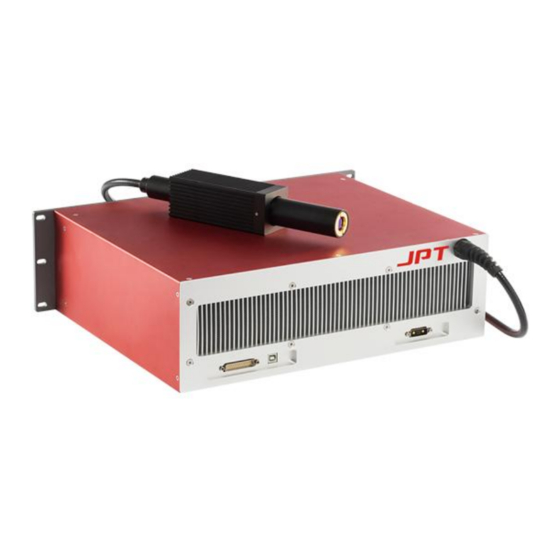
Besides, the whole fiber based laser cavity enables higher beam quality of the laser output. JPT MOPA fiber laser adopts the standard DB25 interface, and it’s power supplied with 48V/12A DC(150W) or 48V/16A DC(200W), which makes it a good compatibility. A photograph of a typical JPT MOPA fiber laser is as shown below. -
Page 5: Packaging List
(5) Please ensure the power is off before install and uninstall this fiber laser. (6) Never look at the fiber laser head, and please wear laser goggle when operate this fiber laser; Shenzhen JPT Opto -Electronics Co. Ltd. Version :B Date:2018.9... -
Page 6: Ydflp Product Series Naming Convention
LP series Single mode 5. Optical Fiber Types Low mode High mode 6. Customized Without: Standard product; R:Built-in red pilot laser Table 3 Naming Convention for Pulsed Fiber Laser For example: Shenzhen JPT Opto -Electronics Co. Ltd. Version :B Date:2018.9... -
Page 7: Technical Specifications
0 ~ 100 ℃ Operation Temperature Range 0 ~ 40 0 ~ 40 ℃ Storage Temperature Range -10 ~ 60 -10 ~ 60 Dimension 430*351*133 430*351*140 Package size 800*550*180 800*550*180 Weight 24.8 24.8 Shenzhen JPT Opto -Electronics Co. Ltd. Version :B Date:2018.9... - Page 8 Below is the chart that shows the change between frequency and output: Figure 3 Cut-off Frequency & Output power relationship charts Shenzhen JPT Opto -Electronics Co. Ltd. Version :B Date:2018.9...
- Page 9 YDFLP-150/200-M7-L1-X user manual Waveform of YDFLP-150-M7-L1 Waveform of YDFLP-200-M7-L1 Figure 4 Shenzhen JPT Opto -Electronics Co. Ltd. Version :B Date:2018.9...
-
Page 10: Installation
YDFLP-150/200-M7-L1-X user manual 2. Installation 2.1 Dimension 1.1 Dimension of main body ( ) YDFLP-150-M7-L1 1.2 Dimension of main body ( ) YDFLP-200-M7-L1 Figure 5 Mechanical Dimension of Fiber Laser Module (Unit: mm) Shenzhen JPT Opto -Electronics Co. Ltd. Version :B Date:2018.9... -
Page 11: Installation Steps
Figure 8 Color code of the power supply cable 3) Ensure that the control interface of the external controller can match the laser, and then connect the control cable to the laser and fix it. Shenzhen JPT Opto -Electronics Co. Ltd. Version :B Date:2018.9... -
Page 12: Laser Connector
PIN_A1 and PIN_2 in Table 6 connect to “+” in Figure 8 , PIN_A2 connect to“-”,PIN_ 5 Connect to“GND”. If need power separately, please separate the PIN_A1 and PIN_2. 3.2 RS232 connector Figure 9 RS232 connector DB9 Table 7 PIN# Description No need to connect 1,4,6-9 Shenzhen JPT Opto -Electronics Co. Ltd. Version :B Date:2018.9... -
Page 13: Control Interface
The system can receive the PA only after the laser is on for 12s and the MO is H. Frequency Modulation (TTL) Shenzhen JPT Opto -Electronics Co. Ltd. Version :B Date:2018.9... -
Page 14: Interface Setting
Setting 2 Setting 3 Setting 4 PIN 1 PIN 2 PIN 3 PIN 4 PIN 5 PIN 6 PIN 7 PIN 8 Current ~50 % ~75 % ~87.5 % ~93.75 % Shenzhen JPT Opto -Electronics Co. Ltd. Version :B Date:2018.9... - Page 15 (Just like: long time no connect control card, high temperature, high frequency signal, low 48V power supply) the fiber laser will stop to receive the instruction. Please turn on the fiber laser power supply again if you want to recover the machine. Shenzhen JPT Opto -Electronics Co. Ltd. Version :B Date:2018.9...
-
Page 16: Pulse Width Control Instruction Structure
10us after all change finished. All instruction design start with 0xA5 byte 4)Please set up low Pin19 before use the extend configuration. 3.3.3 Pulse width control instruction code Shenzhen JPT Opto -Electronics Co. Ltd. Version :B Date:2018.9... -
Page 17: Pulse Energy Control Clock Diagram
(please refer to the user manual for specific pulse width). If the value of pulse width is out of the range of specified pulse width, the laser will choose the default pulse width set last time. Shenzhen JPT Opto -Electronics Co. Ltd. Version :B Date:2018.9... -
Page 18: Jpt Gui
YDFLP-150/200-M7-L1-X user manual 4.JPT GUI 4.1 GUI installation Shenzhen JPT Opto -Electronics Co. Ltd. Version :B Date:2018.9... -
Page 19: Introduction
YDFLP-150/200-M7-L1-X user manual 4.2 Introduction 1. JPT laser GUI software has: laser control, setting the default parameters, operation tips, prompt feedback, setting the control mode and the alarm monitoring. In addition, DB25 interface monitoring and internal parameter monitoring functions are available in GUI. -
Page 20: Gui Operation
If you choose the GUI control, this setting will be saved automatically after the power down, so please cancel the GUI control mode, if you don’t want to use the GUI to control the laser. Shenzhen JPT Opto -Electronics Co. Ltd. Version :B Date:2018.9... - Page 21 The default SIMMER: can control the height of the first pulse, the higher the value, the larger the first pulse. [ APPROPRIATE SIMMER] Shenzhen JPT Opto -Electronics Co. Ltd. Version :B Date:2018.9...
- Page 22 (the system will calculate the external frequency signal firstly, and then their parameters of pulse signal, if the control card without external frequency signal can use the model to define the default frequency of laser) Default External Frequency Mode External Frequency Shenzhen JPT Opto -Electronics Co. Ltd. Version :B Date:2018.9...
- Page 23 PIN9 is power latch signal and the function is enabled if checked, rising edge is effective. The default is not checked. PIN23 is for stop signal and the function is enabled if checked, low level effective, the default is not checked. Shenzhen JPT Opto -Electronics Co. Ltd. Version :B Date:2018.9...
-
Page 24: Check The State Of The Laser
To test the fiber laser, firstly please set the power to 0% and draw a simple figure using the laser marking software, drive the marking and observe the laser output using the frequency doubling Shenzhen JPT Opto -Electronics Co. Ltd. Version :B Date:2018.9... -
Page 25: Precautions During The Laser Operation
This manual for user operation purpose,official service and warranty will Follow the actual sales contract and terms and condition. Thanks for your support. Shenzhen JPT Opto -Electronics Co. Ltd. Version :B Date:2018.9...
Need help?
Do you have a question about the YDFLP-150-M7-L1-X and is the answer not in the manual?
Questions and answers