Table of Contents
Advertisement
Quick Links
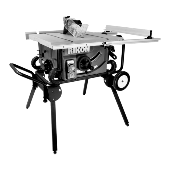
11-600S
10" Portable Table Saw w/Stand
Operator's Manual
Record the serial number and date of purchase in your manual for future reference.
Serial Number: _________________________
Date of purchase: _________________________
For technical support or parts questions, email techsupport@rikontools.com or call toll free at (877)884-5167
www.rikontools.com
11-600SM1
Advertisement
Table of Contents

Related Manuals for Rikon Power Tools 11-600S


Summary of Contents for Rikon Power Tools 11-600S
- Page 1 11-600S 10” Portable Table Saw w/Stand Operator’s Manual Record the serial number and date of purchase in your manual for future reference. Serial Number: _________________________ Date of purchase: _________________________ For technical support or parts questions, email techsupport@rikontools.com or call toll free at (877)884-5167 www.rikontools.com...
-
Page 2: Table Of Contents
TOOL SHOULD BE MAINTAINED TABLE OF CONTENTS • Always unplug tool prior to inspection. Safety Rules................2-5 • Consult manual for specific maintaining and adjusting Unpacking ..................5 procedures. Assembly..................6-9 • Keep tool lubricated and clean for safest operation. Installation & Specifications.. - Page 3 LOCATION The push stick and push block examples shown on page 4 are useful for keeping hands and fingers away from saw The saw should be positioned so neither the operator nor a blade during ripping, rabbeting and dadoing. Apply down- casual observer is forced to stand in line with the saw blade.
- Page 4 USE ONLY ACCESSORIES DESIGNED FOR SAW • Crosscutting operations are worked more conveniently and with greater safety if an auxiliary wood facing is attached to miter gauge using holes provided. However, facing must not interfere with proper functioning of saw blade guard. •...
-
Page 5: Unpacking
THINK SAFETY Safety is a combination of operator common sense and alertness at all times when the saw is being used. Never use another person as a substitute for a table extension, or as additional support for a workpiece that is longer or wider than basic saw table, or to assist in feeding, supporting or pulling the workpiece. -
Page 6: Assembly
ASSEMBLY • Place Rip Fence over the two screws on the rear rail and over the single screw and lock knob on the front rail. Fig-5. CAUTION: Do not attempt assembly if parts are missing. Use this manual to order replacement parts. Figure 5 Be certain all parts are clean and free of shipping preservative. - Page 7 BLADE GUARD ASSEMBLY REAR TABLE EXTENSION ASSEMBLY CONT. WARNING: DISCONNECT MACHINE FROM POWER • Lay the saw upside down. Protect the table top with SOURCE BEFORE CONTINUING STEPS BELOW. cardboard from the carton. • Remove the table insert by turning the lock knob •...
- Page 8 PORTABLE STAND ASSEMBLY BLADE GUARD ASSEMBLY (Continued from page 7) Use the tools supplied for the stand assembly: WARNING: DISCONNECT MACHINE FROM POWER A. Flat Wrench SOURCE BEFORE CONTINUING STEPS BELOW. B. Hex Wrench • Install the table insert over the riving knife. Lock the table insert in place by turning the lock knob Figure 15 clockwise.
-
Page 9: Installation & Specifications
SECURE SAW ON STAND INSTALLATION Refer to Figures 15,16 & 17. GROUNDING INSTRUCTIONS STEP 1: Press the leg release button to unfold the stand legs as shown in FIG. 17. WARNING: Improper connection of equipment grounding conductor can result in the risk of electrical shock. Equip- STEP 2: Place the table saw unit on the stand. -
Page 10: Operation
The RIKON 10” Portable Table Saw w/Stand Model Number • Never leave saw unattended while the power is on. 11-600S, offers precise cutting performance for all woods up • To turn the table saw off, press the Red OFF button. - Page 11 WARNING: For your own safety, lower blade below table BLADE HEIGHT ADJUSTMENT surface. If blade is tilted, return it to vertical position. Turn off • Blade height is controlled by handwheel on the front of the safety disconnect or circuit breaker when saw is not in use. saw.
- Page 12 TYPES OF SAWING OPERATIONS CHANGING THE SAW BLADE Refer to Figure 25. WARNING: For your own safety, always observe the following safety precautions. WARNING: Turn the power switch “OFF” and unplug the power cord from its power source when changing the saw •...
- Page 13 RABBETING WARNING: Certain workpiece shapes, such as molding may not lift the blade guard assembly properly. With the power off, This cut is performed with either the miter gauge or rip fence. feed the workpiece slowly into the blade guard area and until Rabbeting is used to cut out a section of the corner of a the workpiece touches the blade.
-
Page 14: Adjustments
TABLE INSERT ADJUSTMENT ADJUSTMENTS Refer to Figure 26. • The table insert must always be level with the saw table. 90° STOP ADJUSTMENTS • Place a straight edge across the front and rear of the table • Raise saw blade above table as far as possible. Set blade insert. -
Page 15: Maintenance
CURSOR ADJUSTMENT MAINTENANCE Refer to Figure 28. • Raise the saw blade above the table. WARNING: Do not attempt under any circumstances, to service, repair, dismantle, or disassemble any mechanical • Position the fence several inches to the right of the saw or electrical components without physically disconnecting all blade. -
Page 17: Parts Diagrams & Lists
PARTS DIAGRAM & PARTS LIST 1 NOTE: Please reference the Blade Guard Manufacturer’s Part Number Assembly when calling for Replacement Parts. For Parts under Warranty, the Serial Number of your machine is required. KEY NO. MFG. PART NO. DESCRIPTION P11-600S-1 Blade Guard Assembly P11-600S-1.1 Side Guard (Right) - Page 18 PARTS DIAGRAM 2 Fence Table Top Table Bottom 17.0 Fence Lock Assembly NOTE: Please reference the Manufacturer’s Part Number when calling for Replacement Parts. For Parts under Warranty, the Serial Number of your machine is required.
- Page 19 PARTS LIST 2 NOTE: Please reference the Manufacturer’s Part Number when calling for Replacement Parts. For Parts under Warranty, the Serial Number of your machine is required.
- Page 20 PARTS DIAGRAM 3...
- Page 21 PARTS LIST 3...
- Page 22 PARTS DIAGRAM 4...
- Page 23 PARTS LIST 4...
- Page 24 PARTS DIAGRAM 5...
- Page 25 PARTS LIST 5...
- Page 26 PARTS DIAGRAM 6 Fence Adjustment Assembly Rolling Stand Assembly Rear Support Assembly NOTE: Please reference the Manufacturer’s Part Number when calling for Replacement Parts. For Parts under Warranty, the Serial Number of your machine is required.
-
Page 27: Warranty
® RIKON Power Tools Inc. (“Seller”) warrants to only the original retail consumer/purchaser of our products that each product be free from defects in materials and workmanship for a period of five (5) years from the date the product was purchased at retail. - Page 28 11-600S For more information: 25 Commerce Way North Andover, MA 01845 877-884-5167 / 978-528-5380 techsupport@rikontools.com www.rikontools.com 11-600SM1...
Need help?
Do you have a question about the 11-600S and is the answer not in the manual?
Questions and answers