Table of Contents
Advertisement
Quick Links
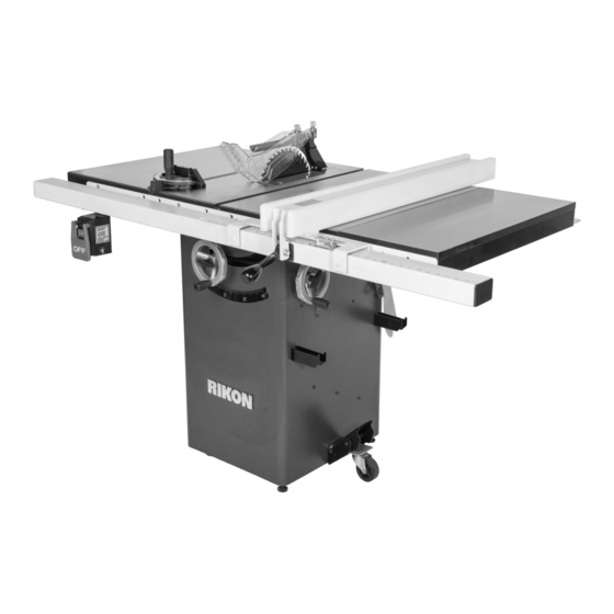
11-200
10" Deluxe Cabinet Saw
Operator's Manual
Record the serial number and date of purchase in your manual for future reference.
Serial Number: _________________________
Date of purchase: _________________________
For technical support or parts questions, email techsupport@rikontools.com or call toll free at (877)884-5167
www.rikontools.com
11-200M1
Advertisement
Table of Contents

Related Manuals for Rikon Power Tools 11-200


Summary of Contents for Rikon Power Tools 11-200
- Page 1 11-200 10” Deluxe Cabinet Saw Operator’s Manual Record the serial number and date of purchase in your manual for future reference. Serial Number: _________________________ Date of purchase: _________________________ For technical support or parts questions, email techsupport@rikontools.com or call toll free at (877)884-5167 www.rikontools.com...
-
Page 2: Table Of Contents
TABLE OF CONTENTS Specifications........................2 Safety Instructions ......................3 - 6 & 23 - 24 Getting To Know Your Cabinet Saw ....................7 Contents of Package .....................8 - 9 Installation ........................10 Assembly ......................... 10 - 15 Adjustments.......................16 - 21 Operation ........................22 - 24 Maintenance ........................25 Electricals &... -
Page 3: Safety Instructions
SAFETY INSTRUCTIONS IMPORTANT! Safety is the single most important consideration in the operation of this equipment. The following instructions must be followed at all times. Failure to follow all instructions listed below may result in electric shock, fire, and/or serious personal injury. There are certain applications for which this tool was designed. - Page 4 SAFETY INSTRUCTIONS 12. KEEP PROTECTIVE GUARDS IN PLACE AND IN 25. ALWAYS WEAR A DUST MASK TO PREVENT WORKING ORDER. INHALING DANGEROUS DUST OR AIRBORNE PARTICLES, including wood dust, crystalline silica dust 13. AVOID ACCIDENTAL STARTING. Make sure that and asbestos dust. Direct particles away from face and the power switch is in the “OFF”...
-
Page 5: Electrical Safety
SAFETY INSTRUCTIONS ELECTRICAL SAFETY EXTENSION CORDS THIS TOOL IS PRE-WIRED FOR 120V THE USE OF AN EXTENSION CORD WITH THIS MACHINE IS NOT RECOMMENDED. For CIRCUITS, AND MUST BE GROUNDED WHILE IN USE TO PROTECT THE OPERATOR FROM ELECTRIC SHOCK. best power and safety, plug the machine directly into a dedicated, grounded electrical outlet that is within the IN THE EVENT OF A MALFUNCTION OR BREAKDOWN,... -
Page 6: Save These Instructions
SAFETY INSTRUCTIONS SPECIFIC SAFETY INSTRUCTIONS FOR TABLE SAWS This machine is intended for the cutting of natural and solid woods.The permissible workpiece dimensions must be observed (see Technical Specification). Any other use not as specified, including modification of the machine or use of parts not tested and approved by the equipment manufacturer, can cause unforeseen damage and invalidate the warranty. -
Page 7: Getting To Know Your Cabinet Saw
GETTING TO KNOW YOUR CABINET SAW A. Motor Cover G. Table Board B. ON / OFF Switch H. Blade Angle Handwheel C. Rip Fence Rail I. Fence Storage Hooks D. Miter Gauge J. Bevel Scale E. Blade Guard Assembly with Riving Knife K. -
Page 8: Contents Of Package
CONTENTS OF PACKAGE Model 11-200 10” Deluxe Cabinet Saw body is shipped complete in one box. The fence assembly is shipped separately. Instructions for assembly and use of the fence are provided separate from this manual. Unpacking, Checking Contents & Clean-up 1. -
Page 9: Contents Of Package
CONTENTS OF PACKAGE TABLE OF LOOSE PARTS continued Extension Wing Screw Package: A. M8 Flat Washer (8) B. M8 Lock Washer (8) C. 8mm x 50mm Hex Allen Bolt (8) Fence Bracket Package: D. M4 x 8mm Round HD Tap Screw (2) E. -
Page 10: Installation
INSTALLATION MOVING & INSTALLING THE SAW The table saw is heavy - over 350 3. Align the machine so that during use, the material lbs! It is best to assemble the machine near the being cut will not face aisles, doorways, or other work area where it will eventually reside. - Page 11 ASSEMBLY THE MACHINE MUST NOT BE PLUGGED IN AND THE POWER SWITCH MUST BE IN THE OFF POSITION UNTIL ASSEMBLY IS COMPLETE. HANDWHEEL ASSEMBLY 1. Place one of the handwheels (A-Fig. 3) onto the shaft to raise/lower the blade (B-Fig. 3) located on the front of the cabinet.
- Page 12 ASSEMBLY EXTENSION WING INSTALLATION The extension wings are heavy; two people are required for assembly. 1.One person is required to lift an extension wing into position. The extension wing will sit into alignment pins to help locate the postion. (A-Fig. 2.
-
Page 13: Installation Instructions
NOTE: Please refer to the Rip Fence Operator’s Manual (cover shown right) provided in the Rip Fence carton for switch installation instructions. (Shown on Model 11-200) RIP FENCE ASSEMBLY Operator’s Manual NOTE: Please refer to the Rip Fence Record the serial number and date of purchase in your manual for future reference. - Page 14 ASSEMBLY THE MACHINE MUST NOT BE PLUGGED IN AND THE POWER SWITCH MUST BE IN THE OFF POSITION UNTIL ASSEMBLY IS COMPLETE. BLADE ASSEMBLY 1. Remove the hex nut (A-Fig. 13) and outer flange (B-Fig. 13) from the blade arbor (C-Fig. 13).
- Page 15 ASSEMBLY THE MACHINE MUST NOT BE PLUGGED IN AND THE POWER SWITCH MUST BE IN THE OFF POSITION UNTIL ASSEMBLY IS COMPLETE. CHANGING THE SPLITTER TO A RIVING KNIFE Note: It is very important to keep the Riving Knife in close proximity to the blade to maintain an even gap inside the kerf of the workpiece.
-
Page 16: Adjustments
ADJUSTMENTS RAISING AND LOWERING THE BLADE The blade height adjustment handwheel and handwheel lock knob are located on the front of the cabinet above the blade angle scale. To raise the saw blade, loosen the handwheel lock knob (A-Fig. 20) (counterclockwise) and turn the hand- wheel (B-Fig. - Page 17 ADJUSTMENTS ADJUSTING BLADE ANGLE POSITIVE STOPS 1. Raise the saw blade (A-Fig. 22) to its highest position using the handwheel on the front of the saw. (See RAISING AND LOWERING THE BLADE on page sixteen) 2. Using an angle or combination square (B-Fig. 22) check that the blade is 90 degrees to the saw table (zero degrees on blade angle scale).
- Page 18 ADJUSTMENTS CHECKING BLADE ALIGNMENT The blade is set parallel at the factory and should not need any adjustments. You can check this by using a dial indicator (not included) or a combina- tion square (not included). It is recommended to check the alignment before initial operation as follows: THE MACHINE MUST NOT BE...
- Page 19 ADJUSTMENTS ADJUSTING BLADE ALIGNMENT NOTICE: Blade alignment is factory set and should not need adjustment. All saw blades have some runout. Therefore, readjusting the blade alignment should only be attempted if it A (x6) becomes necessary (see CHECKING BLADE ALIGNMENT on page eighteen). THE MACHINE MUST NOT BE PLUGGED IN AND THE POWER SWITCH MUST BE IN THE OFF POSITION UNTIL ASSEMBLY IS COMPLETE.
- Page 20 ADJUSTMENTS BLADE ANGLE SCALE ARROW ADJUSTMENT 1. Make certain that the blade is set 90 degrees to the table surface with a combination square. See page 17, figure 22 ADJUSTING BLADE ANGLE POSITIVE STOPS. 2. Check that the bevel arrow is pointing to the zero degree mark on the bevel scale located on the front of the cabinet.
- Page 21 ADJUSTMENTS MITER GAUGE ADJUSTMENT 1. The miter gauge has adjustable positive stops at 0-degree and 45-degrees or it can be manu- ally set at any angle between 60-degrees. 2. To rotate the miter gauge body (A-Fig. 32), loosen knob (B-Fig. 32) and pull out plunger (C-Fig.
-
Page 22: Operation
OPERATION A separate electrical circuit should be used for this table saw. The circuit should not be less than #14AWG wire and should be protected with a 15- amp breaker. Have a qualified electrician repair or replace damaged or worn cord immediately. Before connecting the motor to the power source, make certain the switch is in the “OFF”... - Page 23 OPERATION CROSSCUTTING TYPES OF SAWING OPERATIONS WARNING: Use caution when starting the cut to WARNING: For your own safety, always observe the prevent binding of the guard against the workpiece. following safety precautions. This cut is performed with the miter gauge set at “0”, and is used for cutting across the workpiece grain at •...
-
Page 24: Operation
OPERATION RIPPING DADOING WARNING: When bevel ripping and whenever possible, This cut is performed with either the miter gauge or rip place the fence on the side of the blade so that the blade fence. Dadoing is done with a set of blades (dado set) is tilted away from the fence and hands. -
Page 25: Maintenance
MAINTENANCE BEFORE CLEANING OR CARRYING OUT MAINTENANCE WORK, DISCONNECT THE MACHINE FROM THE POWER SOURCE (WALL SOCKET). NEVER USE WATER OR OTHER LIQUIDS TO CLEAN THE MACHINE. USE A BENCH BRUSH. DO NOT USE COMPRESSED AIR NEAR BEARINGS. REGULAR MAINTENANCE OF THE MACHINE WILL PREVENT UNNECESSARY PROBLEMS. 1. -
Page 26: Troubleshooting
TROUBLESHOOTING FOR YOUR OWN SAFETY, ALWAYS TURN OFF AND UNPLUG THE MACHINE BEFORE CARRYING OUT ANY TROUBLESHOOTING. For parts or technical questions contact: techsupport@rikontools.com or 877-884-5167. -
Page 27: Notes
NOTES Use this section to record maintenance, service and any calls to Technical Support:... -
Page 28: Parts Diagrams & Parts Lists
PARTS DIAGRAM SAFETY GUARD, SPLITTER & RIVING KNIFE... - Page 29 PARTS LIST SAFETY GUARD, SPLITTER & RIVING KNIFE...
- Page 30 PARTS DIAGRAM MAIN TABLE & EXTENSION WINGS SWITCH & CORD ASSEMBLY...
- Page 31 PARTS LIST MAIN TABLE & EXTENSION WINGS KEY NO. DESCRIPTION PART NO. LEFT EXTENSION WING P11-200-40 1/4-28 X 3/8” NYLON SET SCREW P11-200-41 TABLE INSERT P11-200-44 M8X6mm MAGNET P11-200-48 TABLE ASS`Y P11-200-49 RIGHT EXTENSION WING P11-200-52 5/16-18 X45mm HEX SOC SET SCR P11-200-54 M8 LOCK WASHER P11-200-55...
- Page 32 PARTS DIAGRAM MITER GAUGE...
- Page 33 PARTS LIST MITER GAUGE DESCRIPTION PART NO. KEY NO. MITER GAUGE BODY P11-200-114 SPECIAL WASHER P11-200-115 SPECIAL SCREW P11-200-116 GUIDE BAR P11-200-119 M4 X 16mm SET SCREW P11-200-120 1/4”x3/4 PIN P11-200-121 M4X10mm PAN HEAD SCREW P11-200-122 122A M4 FLAT WASHER P11-200-122A PLUNGER P11-200-123...
- Page 34 PARTS DIAGRAM MOTOR & TRUNNION...
- Page 35 PARTS LIST MOTOR & TRUNNION...
- Page 36 PARTS DIAGRAM SAW CABINET...
- Page 37 PARTS LIST SAW CABINET...
-
Page 38: Warranty
WARRANTY... -
Page 39: Accessories
ACCESSORIES NOTES 13-299 DADO BLADE TABLE INSERT Quality cast aluminum construction with 1-1/8” x 7-5/8” blade opening. Includes four leveling screws. C10-100 PUSH STICK Keep your hands clear of the blade with this rigid plastic push stick. Ergonomic design helps you push material through a saw, router or other cutting devices giving you better control of the workpiece while providing safety. - Page 40 11-200 For more information: 16 Progress Road Billerica, MA 01821 877-884-5167 / 978-528-5380 techsupport@rikontools.com www.rikontools.com 11-200M1...
Need help?
Do you have a question about the 11-200 and is the answer not in the manual?
Questions and answers