Table of Contents
Advertisement
Quick Links
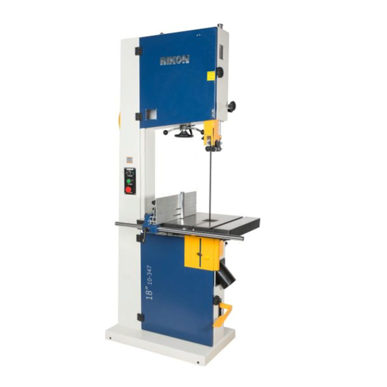
10-347
18" Professional Bandsaw
4001824
Operator's Manual
Record the serial number and date of purchase in your manual for future reference.
Serial Number: _________________________
Date of purchase: _________________________
For technical support or parts questions, email techsupport@rikontools.com or call toll free at (877)884-5167
www.rikontools.com
10-347M1
Advertisement
Table of Contents
Troubleshooting

Related Manuals for Rikon Power Tools 10-347


Summary of Contents for Rikon Power Tools 10-347
- Page 1 10-347 18” Professional Bandsaw 4001824 Operator’s Manual Record the serial number and date of purchase in your manual for future reference. Serial Number: _________________________ Date of purchase: _________________________ For technical support or parts questions, email techsupport@rikontools.com or call toll free at (877)884-5167 www.rikontools.com...
-
Page 2: Table Of Contents
TABLE OF CONTENTS Specifications........................2 Safety Instructions ......................3 - 6 Getting To Know Your Machine ..................7 Contents of Package ....................8 - 9 Assembly .........................10 - 11 Adjustments.......................12 - 18 Operation ........................19 - 20 Maintenance ........................21 Wiring Diagram ........................21 Troubleshooting ......................22 - 25 Parts Explosions &... -
Page 3: Safety Instructions
SAFETY INSTRUCTIONS IMPORTANT! Safety is the single most important consideration in the operation of this equipment. The following instructions must be followed at all times. Failure to follow all instructions listed below may result in electric shock, fire, and/or serious personal injury. There are certain applications for which this tool was designed. - Page 4 SAFETY INSTRUCTIONS 12. KEEP PROTECTIVE GUARDS IN PLACE AND IN 25. ALWAYS WEAR A DUST MASK TO PREVENT WORKING ORDER. INHALING DANGEROUS DUST OR AIRBORNE PARTICLES, including wood dust, crystalline silica dust 13. AVOID ACCIDENTAL STARTING. Make sure that the and asbestos dust.
-
Page 5: Extension Cords
SAFETY INSTRUCTIONS EXTENSION CORDS ELECTRICAL SAFETY USE OF AN EXTENSION CORD THIS TOOL REQUIRES THE INSTALLATION OF WITH THIS MACHINE IS NOT RECOMMENDED. FOR A 220V PLUG (NOT INCLUDED), AND MUST BE BEST POWER AND SAFETY, PLUG THE MACHINE GROUNDED WHILE IN USE TO PROTECT THE DIRECTLY INTO A DEDICATED GROUNDED ELECTRI- OPERATOR FROM ELECTRIC SHOCK. - Page 6 SAFETY INSTRUCTIONS SPECIFIC SAFETY INSTRUCTIONS FOR BAND SAWS This machine is intended for the cutting of natural, solid woods, composite materials, plastics and non-ferrus metals. The permissible workpiece dimensions must be observed (see Technical Specification). Any other use not as specified, including modification of the machine or use of parts not tested and approved by the equipment manufacturer, can cause unforeseen damage and invalidate the warranty.
-
Page 7: Getting To Know Your Machine
GETTING TO KNOW YOUR MACHINE A. Support Ring K. Work Table B. Tension Indicator Window L. Lower Door Blade Guard C. Blade Tension Hand Wheel M. 4” Dust Ports D. Switch N. Foot Brake E. Rip Fence O. Blade Tracking Knob F. -
Page 8: Contents Of Package
CONTENTS OF PACKAGE Model 10-347 18” Professional Bandsaw is shipped complete in one crate. Unpacking, Checking Contents & Clean-up 1. Carefully remove all contents from the shipping carton. Compare the contents with the list of contents to make sure that all of the items are accounted for, before discarding any packing material. Place parts on a protected surface for easy identification and assembly. -
Page 9: Contents Of Package
CONTENTS OF PACKAGE Table & Rip Fence Assembly: A. Table B. Rip Fence Rail C. Fence Rail Hardware: 1. Hex Nut M10 (x4) 2. Flat Washer M10 (x4) D. Rip Fence E. Rip Fence Carrier F. Resaw Bar Bandsaw Accessories: A. -
Page 10: Assembly
ASSEMBLY THE MACHINE MUST NOT BE PLUGGED IN AND THE POWER SWITCH MUST BE IN THE OFF POSITION UNTIL ASSEMBLY IS COMPLETE. INSTALLING THE WORK TABLE The Work Table is extremely heavy. It may require two other individuals to assist with the installation. - Page 11 ASSEMBLY / ADJUSTMENTS RIP FENCE ASSEMBLY Note: Part numbers referred below can be found on page 36 of this manual. 1. Mount the fence Guide Rail (#12F) onto the front table edge with the two fence bar Nuts and Washers (#14F, 5F) Fig.
- Page 12 ASSEMBLY / ADJUSTMENTS SETTING THE TABLE SQUARE TO SAW BLADE The table may be set at 90° to the saw blade sides by adjusting the table stop screw (A-Fig.9) under the table. The table stop screw rests on the top of the quick release adjustment stop (B-Fig.9).
-
Page 13: Adjustments
ADJUSTING THE BLADE TENSION Figure 13 The 10-347 has a Quick Release blade function which allows for fast blade changing and tensioning. The Quick Release Lever is shown in Figure 13. To loosen the tension of the blade, turn the blade tension hand wheel, or lever, (A-Fig.14) counter clockwise. - Page 14 ADJUSTMENTS CHANGING THE BANDSAW BLADE Unplug the machine from the electrical supply. This ensures that the Bandsaw will not accidentally turn on if the ON/OFF switch is bumped. Wear gloves for protection. Figure 16 a) Open the top and bottom wheel doors by turning the door locking knobs.
- Page 15 ADJUSTMENTS ADJUSTING THE SPRING LOADED BLADE GUIDES NOTE: Blade Guard removed for photo purposes 1/16” Unplug the machine from the electrical supply. This ensures that the Bandsaw will not accidentally turn on if the ON/OFF switch is bumped. Upper Guides: To adjust the upper blade guides, first position the roller guides relative to the blade by loosening the Lock Handle (A-Fig.20) and sliding Figure 20...
- Page 16 (Fig.24) Figure 23 ADJUSTING THE RIP FENCE FOR DRIFT The 10-347 Bandsaw features an innovative fence system that will easily adjust to eliminate ‘drift’, and bring the fence back to being parallel to the blade. Plus, it allows quick changing of the fence from a vertical to horizontal position, or for use to the left or right of the blade.
- Page 17 ADJUSTMENTS ADJUSTING THE FENCE TO THE TABLE Check that the fence is lying flat, or parallel to the table surface. The gap between the table and the bottom of the fence should be equal along the whole length of the fence. If a slight adjustment is necessary, the Nylon Plate (#25F), that is located at the front base of the Fence Carrier (#9F), can be turned to raise or lower the fence distance over the table.
- Page 18 ADJUSTMENTS side of the carrier. Then rotate the fence 180° end-to- end and slide it back onto the carrier. Fig. 30 & 31. 4. Once in place, retighten the side handle to secure the fence in position on the carrier. Fig. 31. 5.
-
Page 19: Operation
Use a miter gauge for cross-cut or angle cutting. ON/OFF SWITCH CONTROL STATION The 10-347 has a key-on safety feature that will lock out unauthorized users such as students, coworkers or employees not trained or qualified to use the bandsaw. - Page 20 The tension lever that operates the quick release blade function has two of the most innovative features on the 10-347. (Fig. 38) One feature allows the blade tension to be released from back or front of the saw. Operate Quick Release from...
-
Page 21: Maintenance
MAINTENANCE BEFORE CLEANING OR CARRYING OUT MAINTENANCE WORK, DISCONNECT THE MACHINE FROM THE POWER SOURCE (WALL SOCKET). NEVER USE WATER OR OTHER LIQUIDS TO CLEAN THE MACHINE. USE A BENCH BRUSH. DO NOT USE COMPRESSED AIR NEAR BEARINGS. REGULAR MAINTENANCE OF THE MACHINE WILL PREVENT UNNECESSARY PROBLEMS. -
Page 22: Troubleshooting
TROUBLESHOOTING FOR YOUR OWN SAFETY, ALWAYS TURN OFF AND UNPLUG THE MACHINE BEFORE CARRYING OUT ANY TROUBLESHOOTING. TROUBLE PROBABLE CAUSE REMEDY The machine does not 1. No power supply. Check the cable for breakage. work when switched on. 2. Defective switch. Contact your local dealer for repair. - Page 23 TROUBLESHOOTING CHANGING THE MOTOR DRIVE BELT (Refer to “Frame Assembly” parts diagram on page 26 and “Wheel Assembly” parts diagram on page 28) Before changing the belt, make sure that the bandsaw is unplugged from the power source. Release the saw blade tension from the drive belt by turning the quick release blade tension lever. From the inside the machine, loosen the two Hex Bolts (Part #92A, Fig.
- Page 24 TROUBLESHOOTING LOWER WHEEL ADJUSTMENTS The following instructions will correct common blade issues related to the lower wheel’s alignment in relation to the upper wheel. These adjustments will correct the blade position on the lower wheel and blade oscillation (wobble). These are critical adjustments which affect the performance and accuracy of the bandsaw.
-
Page 25: Troubleshooting
TROUBLESHOOTING If a blade is tracking on the rear of the lower wheel, away from the door, follow these steps: De-tension the saw blade. Loosen 9 o’clock shaft bolt to take pressure off the shaft. Loosen 6 o’clock shaft bolt one half rotation. Tighten the 12 o’clock shaft bolt until the shaft touches the 6 o’clock adjusting bolt. -
Page 26: Parts Explosions & Parts Lists
PARTS DIAGRAM FRAME ASSEMBLY A... - Page 27 PARTS LIST FRAME ASSEMBLY A KEY NO. DESCRIPTION QTY MFG. PART NO. KEY NO. DESCRIPTION QTY MFG. PART Support Ring P10-347-1A Clamp handle P10-347-67A Cross recess pan hd screw M5X10 P10-347-2A Self-locking nut P10-347-68A Tool holder P10-347-3A Gear P10-347-69A Frame P10-347-4A Belleville spring P10-347-70A...
- Page 28 PARTS DIAGRAM WHEEL ASSEMBLY B...
- Page 29 PARTS LIST WHEEL ASSEMBLY B KEY NO. DESCRIPTION MFG. PART NO. Hex socket cap screw M8X16 P10-347-1B Washer P10-347-2B Circlip P10-347-3B Bearing P10-347-4B Upper wheel P10-347-5B Spacer bushing P10-347-6B Rubber tire P10-347-7B Blade P10-347-8B Lower wheel P10-347-9B NOTE: Please reference the Manufacturer’s Part Number when calling for Replacement Parts. For Parts under Warranty, the serial number of your machine is required.
- Page 30 PARTS DIAGRAM TABLE ASSEMBLY C...
- Page 31 PARTS LIST TABLE ASSEMBLY C KEY NO. DESCRIPTION QTY MFG. PART NO. Hex nut M8 P10-347-1C Hex bolt M8X30 P10-347-2C P10-347-3C Washer P10-347-4C Big washer P10-347-5C Hex socket cap screw M6X10 P10-347-6C Carriage bolt M12X100 P10-347-7C Set screw M12X60 P10-347-8C Hex nut M12 P10-347-9C Hex bolt M10X30...
- Page 32 PARTS DIAGRAM BLADE TENSION & TRACKING D...
- Page 33 PARTS LIST BLADE TENSIONING & TRACKING D KEY NO. DESCRIPTION MFG. PART NO. Cap nut P10-347-1D Spring washer P10-347-2D Big washer P10-347-3D Hex nut M10 P10-347-4D Spring washer P10-347-5D Flat washer P10-347-6D Locking nut P10-347-7D Bolt P10-347-8D Double-thread screw P10-347-9D Set screw M8X25 P10-347-10D Sliding piece...
- Page 34 PARTS DIAGRAM GUIDE POST ASSEMBLY E...
- Page 35 PARTS LIST GUIDE POST ASSEMBLY E KEY NO. DESCRIPTION MFG. PART NO. Circlip ring P10-347-1E Rack P10-347-2E Blade guard assembly P10-347-3E Clamp handle P10-347-4E Window P10-347-5E Cross recess pan hd screw M4X8 P10-347-6E P10-347-7E Clamp handle P10-347-8E Heel block P10-347-9E Spring P10-347-10E Upper guide...
- Page 36 PARTS DIAGRAM & PARTS LIST FENCE ASSEMBLY F NOTE: Please reference the Manufacturer’s Part Number when calling for Replacement Parts. For Parts under Warranty, the serial number of your machine is required. KEY NO. DESCRIPTION MFG. PART NO. Adjust Handle P10-347-1F Locking Knob P10-347-2F...
-
Page 37: Accessories
ACCESSORIES C10-396 TABLE INSERT 13-345 MOBILITY KIT Conversion Kit installs onto the bandsaw base to make it easy to move around the shop. Includes rear wheel Replacement plastic insert with four- assembly, front support, tow bar, hardware and instructions. threaded holes for hex screw levelers. 13-912 ‘T’... -
Page 38: Notes
NOTES Use this section to record maintenance, service and any calls to Technical Support. -
Page 39: Warranty
WARRANTY... - Page 40 10-347 For more information: 16 Progress Rd Billerica, MA 01821 877-884-5167 / 978-528-5380 techsupport@rikontools.com www.rikontools.com 10-347M1...
Need help?
Do you have a question about the 10-347 and is the answer not in the manual?
Questions and answers